table FORD FIESTA 2007 Workshop Manual
[x] Cancel search | Manufacturer: FORD, Model Year: 2007, Model line: FIESTA, Model: FORD FIESTA 2007Pages: 1226, PDF Size: 61.26 MB
Page 696 of 1226
303-01 B-74 Engine - 2.OL Duratec-HE (M14) 303-01 B-74
REMOVAL
Engine
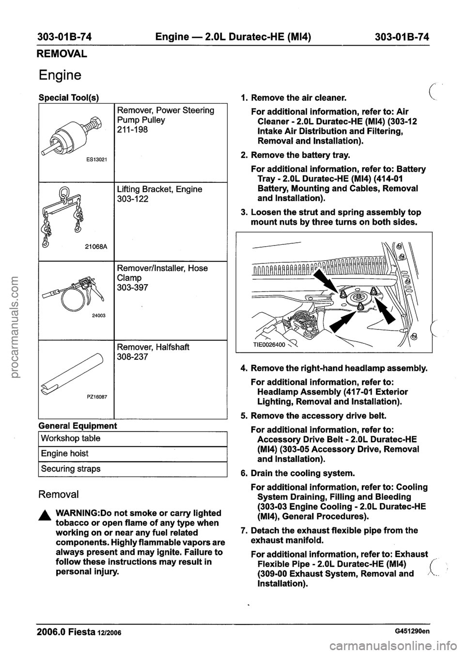
Special Tool(s)
I I Remover, Power Steering I
I I Removerllnstaller, Hose
General Equipment
I Workshop table I
I Engine hoist I
I Securing straps I
Removal
A WARNING:Do not smoke or carry lighted
tobacco or open flame of any type when
working on or near any fuel related
components. Highly flammable vapors are
always present and may ignite. Failure to
follow these instructions may result in
personal injury.
1. Remove the air cleaner. c.
For additional information, refer to: Air
Cleaner
- 2.OL Duratec-HE (M14) (30312
Intake Air Distribution and Filtering,
Removal and Installation).
2. Remove the battery tray.
For additional information, refer to: Battery
Tray
- 2.OL Duratec-HE (M14) (414-01
Battery, Mounting and Cables, Removal
and Installation).
3. Loosen the strut and spring assembly top
mount nuts by three turns on both sides.
4. Remove the right-hand
headlamp assembly.
For additional information, refer to:
Headlamp Assembly (41 7-01 Exterior
Lighting, Removal and Installation).
5. Remove the accessory drive belt.
For additional information, refer to:
Accessory Drive Belt
- 2.OL Duratec-HE
(M14) (303-05 Accessory Drive, Removal
and Installation).
6. Drain the cooling system.
For additional information, refer to: Cooling
System Draining, Filling and Bleeding
(303-03 Engine Cooling
- 2.OL Duratec-HE
(M14), General Procedures).
7. Detach the exhaust flexible pipe from the
exhaust manifold.
For additional information, refer to: Exhaust
Flexible Pipe
- 2.OL Duratec-HE (M14)
(309-00 Exhaust System, Removal and
Installation).
2006.0 Fiesta 1212006 G451290en
procarmanuals.com
Page 699 of 1226
303-01 B-77 Engine - 2.OL Duratec-HE (M14) 303-01 B-77
REMOVAL
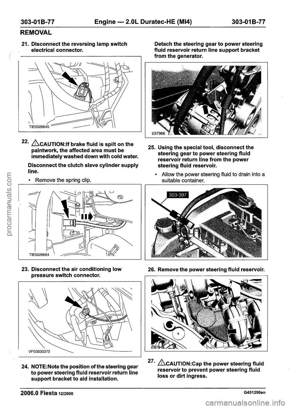
21. Disconnect the reversing lamp switch Detach the steering gear to power steering
electrical connector. fluid
reservoir return line support bracket
from the generator.
22m CAUTION:^^ brake fluid is spilt on the 25s Using the special tool, disconnect the paintwork, the affected area must be
immediately washed down with cold water. steering
gear to power steering fluid
reservoir return line from the power
Disconnect the clutch slave cylinder supply
steering fluid reservoir.
line.
Remove the spring clip. Allow
the power steering fluid to drain into a
suitable container.
23. Disconnect the air conditioning low 26. Remove the power steering fluid reservoir.
pressure switch connector.
24. N0TE:Note the position of the steering gear 27m &AUTION:C~~ the power steering fluid
to power steering fluid reservoir return line reservoir
to prevent power steering fluid
support bracket to aid installation. loss
or dirt ingress.
2006.0 Fiesta 12/2006 G451290en
procarmanuals.com
Page 701 of 1226
303-01 B-79 Engine - 2.OL Duratec-HE (M14) 303-01 B-79
REMOVAL
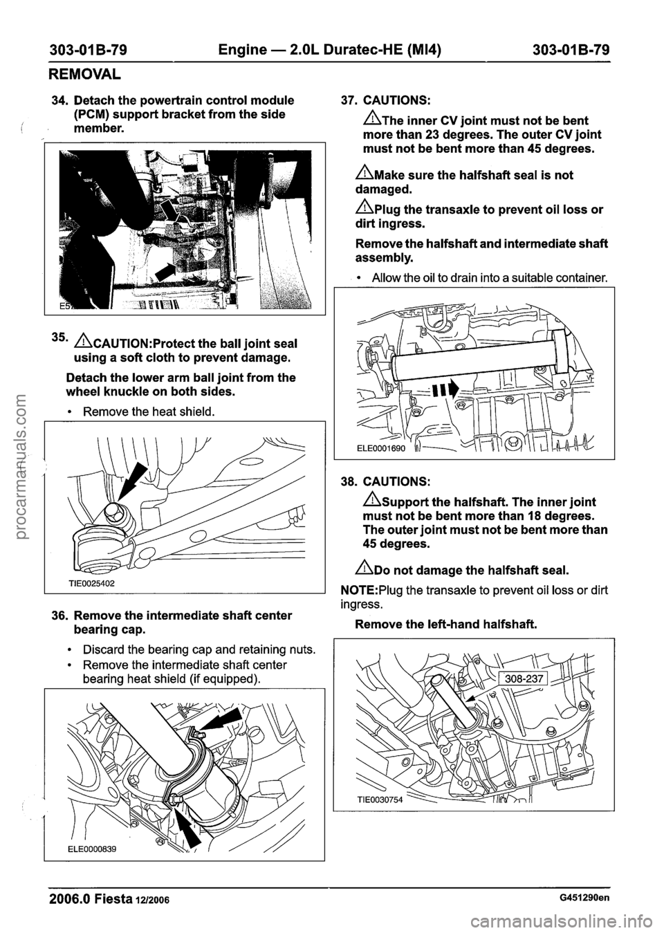
34. Detach the powertrain control module 37. CAUTIONS:
(PCM) support bracket from the side
i member. A~he inner CV joint must not be bent
more than
23 degrees. The outer CV joint
35m ACAUTION:P~~~~~~ the ball joint seal
using
a soft cloth to prevent damage.
Detach the lower arm ball joint from the
wheel knuckle on both sides.
Remove the heat shield.
must not be bent more than 45 degrees.
A~ake sure the halfshaft seal is not
damaged.
Aplug the transaxle to prevent oil loss or
dirt ingress.
Remove the halfshaft and intermediate shaft
assembly.
Allow the oil to drain into a suitable container.
38. CAUTIONS:
Asupport the halfshaft. The inner joint
must not be bent more than
I8 degrees.
The outer joint must not be bent more than
45 degrees.
ADO not damage the halfshaft seal.
N0TE:Plug the transaxle to prevent oil loss or dirt
ingress.
36. Remove the intermediate shaft center
bearing cap. Remove
the left-hand halfshaft.
Discard the bearing cap and retaining nuts.
Remove the intermediate shaft center
bearing heat shield (if equipped).
2006.0 Fiesta 1212006 G451290en
procarmanuals.com
Page 702 of 1226
303-01 B-80 Engine - 2.OL Duratec-HE (M14) 303-01 B-80
REMOVAL
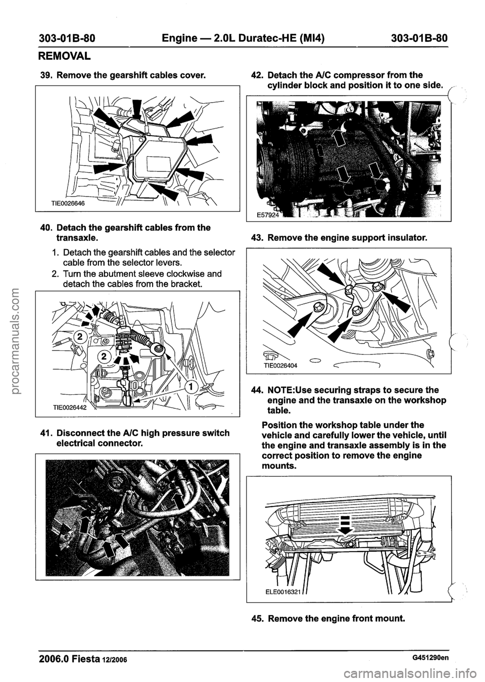
39. Remove the gearshift cables cover. 42. Detach the NC compressor from the
cylinder block and position
it to one side. /-
40. Detach the gearshift cables from the
transaxle. 43.
Remove the engine support insulator.
1. Detach the gearshift cables and the selector
cable from the selector levers.
2. Turn the abutment sleeve clockwise and
detach the cables from the bracket.
44. N0TE:Use securing straps to secure the
engine and the transaxle on the workshop
table.
Position the workshop table under the
41. Disconnect the NC high pressure switch
vehicle and carefully lower the vehicle, until
electrical connector.
the engine and transaxle assembly is in the
correct position to remove the engine
mounts.
45. Remove the engine front mount.
2006.0 Fiesta 1212006 G451290en
procarmanuals.com
Page 703 of 1226
303-01 B-81 Engine - 2.OL Duratec-HE (M14) 303-01 B-81
REMOVAL
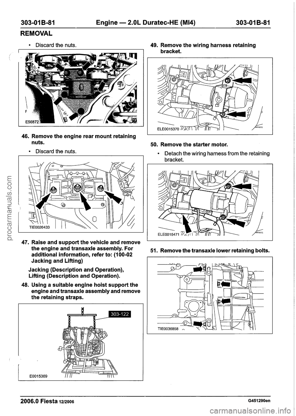
Discard the nuts. 49. Remove the wiring harness retaining
bracket.
46. Remove the engine rear mount retaining
nuts.
50. Remove the starter motor.
Discard the nuts. Detach the wiring harness from the retaining
bracket.
47. Raise and support the vehicle and remove
the engine and transaxle assembly. For
51. Remove the transaxle lower retaining bolts.
additional information, refer to: (1 00-02
Jacking and Lifting)
Jacking (Description and Operation),
Lifting (Description and Operation).
48. Using a suitable engine hoist support the
engine and transaxle assembly and remove
the retaining straps.
2006.0 Fiesta 1212006 G451290en
procarmanuals.com
Page 706 of 1226
303-01 B-84 Engine - 2.OL Duratec-HE (M14) 303-01 B-84
DISASSEMBLY
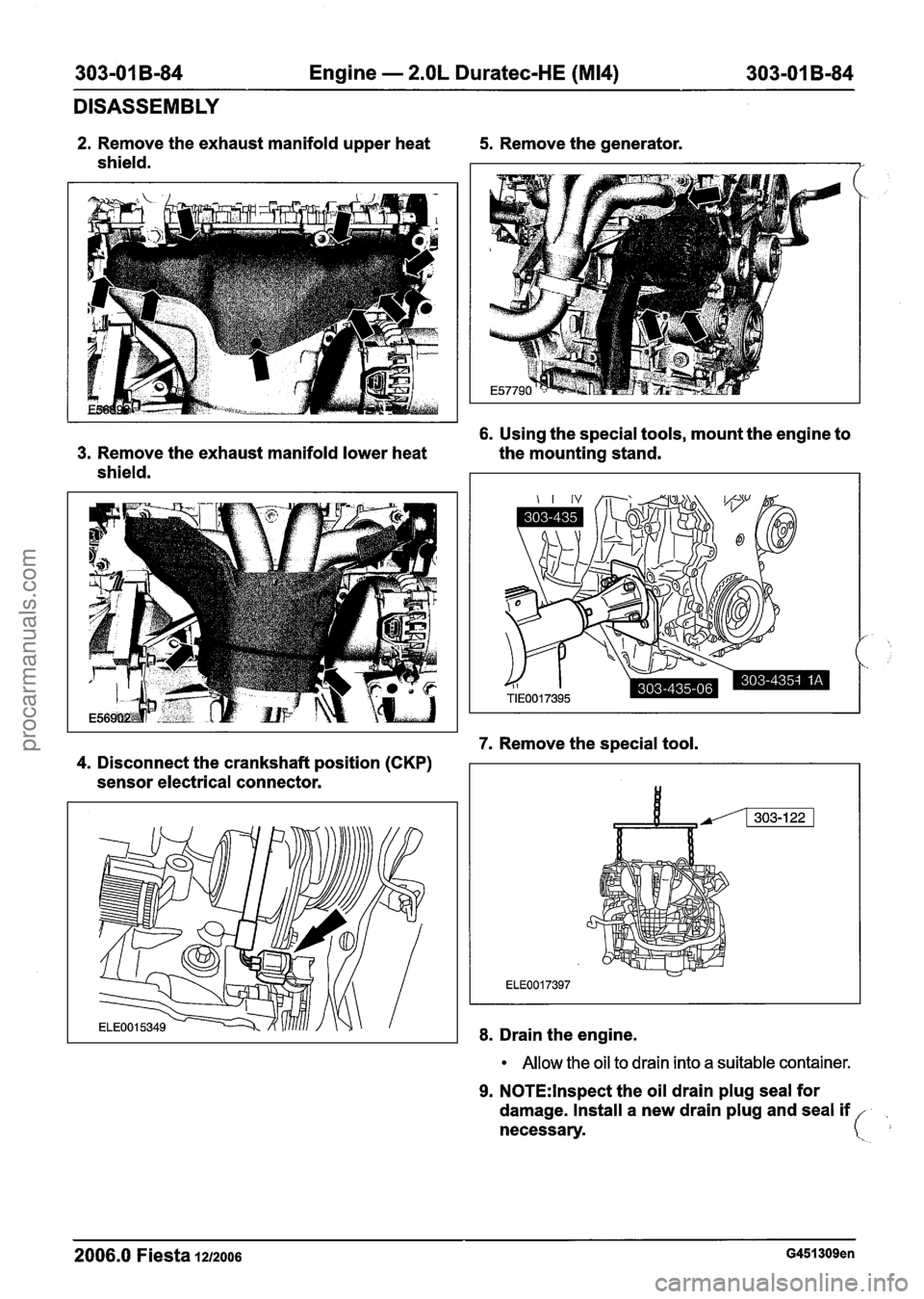
2. Remove the exhaust manifold upper heat 5. Remove the generator.
shield.
6. Using the special tools, mount the engine to
3. Remove the exhaust manifold lower heat the mounting stand.
shield.
7. Remove the special tool.
4. Disconnect the crankshaft position (CKP)
sensor electrical connector.
8. Drain the engine.
Allow the oil to drain into a suitable container.
9. N0TE:lnspect the oil drain plug seal for
damage. Install a new drain plug and seal
if
necessary.
2006.0 Fiesta 1212006 G451309en
procarmanuals.com
Page 712 of 1226
303-01 B-90 Engine - 2.OL Duratec-HE (M14) 303-01 B-90
DISASSEMBLY
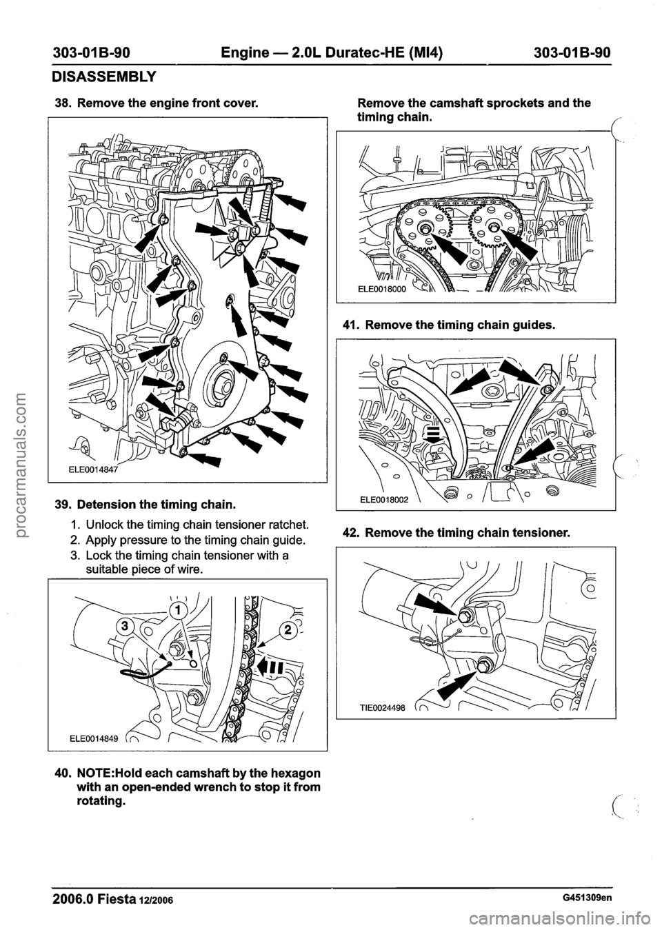
38. Remove the engine front cover.
39. Detension the timing chain. Remove
the camshaft sprockets and the
timing chain.
f
41. Remove the timing chain guides.
I. Unlock the timing chain tensioner ratchet.
2. Apply pressure to the timing chain guide. 42. Remove the timing chain tensioner.
3. Lock the timing chain tensioner with a
suitable piece of wire.
40. N0TE:Hold each camshaft by the hexagon
with an open-ended wrench to stop it from
rotating.
2006.0 Fiesta 1212006 G451309en
procarmanuals.com
Page 718 of 1226
303-01 B-96 Engine - 2.OL Duratec-HE (M14) 303-01 B-96
ASSEMBLY
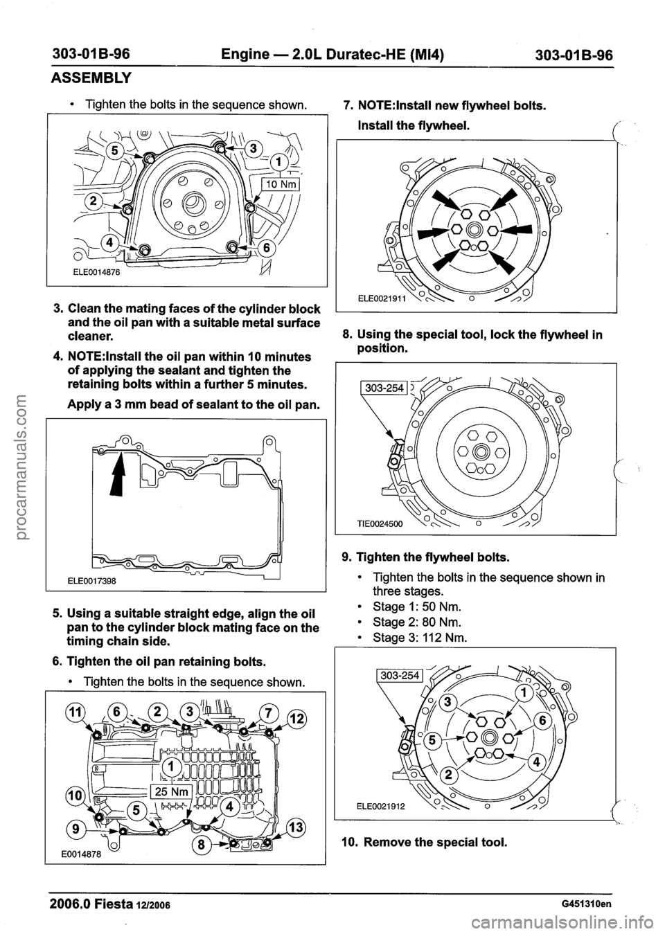
Tighten the bolts in the sequence shown. 7. N0TE:lnstall new flywheel bolts.
Install the flywheel.
Clean the mating faces of the cylinder block
I
and the oil pan with a suitable metal surface
cleaner.
8. Using the special tool, lock the flywheel in
position.
N0TE:lnstall the oil pan within 10 minutes
of applying the sealant and tighten the
retaining bolts within a further
5 minutes.
Apply a
3 mm bead of sealant to the oil pan.
9. Tighten the flywheel bolts.
Tighten the bolts in the sequence shown in
three stages.
5. Using a suitable straight edge, align the oil Stage 1: 50 Nm.
pan to the cylinder block mating face on the Stage 2: 80 Nm.
timing chain side. Stage 3: 11 2 Nm. I I
6. Tighten the oil pan retaining bolts.
Tighten the bolts in the sequence shown.
l I. -.
10. Remove the special tool.
2006.0 Fiesta 1212006 G451310en
procarmanuals.com
Page 722 of 1226
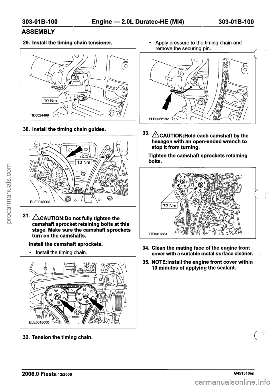
303-01 B-100 Engine - 2.OL Duratec-HE (M14) 303-01 B-I 00
ASSEMBLY
29. Install the timing chain tensioner.
30. Install the timing chain guides.
31 ' ACAUTION:D~ not fully tighten the
camshaft sprocket retaining bolts at this
stage. Make sure the camshaft sprockets
turn on the camshafts.
Install the camshaft sprockets.
Install the timing chain.
32. Tension the timing chain.
Apply pressure to the timing chain and
remove the securing pin.
,
33m ACAUTION:H~I~ each camshaft by the
hexagon with an open-ended wrench to
stop
it from turning.
Tighten the camshaft sprockets retaining
bolts.
34. Clean the mating face of the engine front
cover with a suitable metal surface cleaner.
35. N0TE:lnstall the engine front cover within
10 minutes of applying the sealant.
2006.0 Fiesta 1212006 G451310en
procarmanuals.com
Page 733 of 1226

303-01 B-I11 Engine - 2.OL Duratec-HE (M14) 303-01 B-111
INSTALLATION
Engine
i Special Tool(s)
I
I Remover/lnstaller, Hose
General Equipment
I Workshop table 1
I Securing straps I
I Engine hoist I --
A WARNING:Do not smoke or carry lighted
tobacco or open flame of any type when
working on or near any fuel related
components. Highly flammable vapors are
always present and may ignite. Failure to
follow these instructions may result in
personal injury.
1. N0TE:Using suitable retaining straps, secure
the engine on the workshop table.
Support the engine with wooden blocks.
2. Install the transaxle.
3. Install the transaxle upper retaining bolts.
4. Install the transaxle left-hand retaining bolts.
5. Install the transaxle right-hand retaining
bolts.
2006.0 Fiesta 1212006 ~451291 en
procarmanuals.com