table FORD FIESTA 2007 Manual PDF
[x] Cancel search | Manufacturer: FORD, Model Year: 2007, Model line: FIESTA, Model: FORD FIESTA 2007Pages: 1226, PDF Size: 61.26 MB
Page 489 of 1226
Engine - 1.25L Duratec-1 6V (Sigma)ll.4L
303-01 A-I 3 Duratec-1 6V (Sigma)ll.GL Duratec-1 6V (Sigma) 303-01 A-I
3
GENERAL PROCEDURES
Valve Clearance Adjustment
1. Remove the valve cover. clearance.
I
General Equipment 2. Tappet thickness required = thickness of
currently installed tappet
+ the measured
For additional information, refer to Valve For additional information, refer to
Cover in this section. Specifications in this section.
3. Install the correct tappet.
*' ~AUTION:O~~Y turn the engine in the 7. NOTE:Do not install the timing belt at this normal direction of rotation.
stage.
Feeler gauges
Turn the engine until piston No. 1 is at top
Install the camshafts.
dead center (TDC).
For additional information, refer to
3. N0TE:Note down each cylinder number and
Camshafts in this section.
the valve clearances measured.
8. N0TE:Turn the camshafts to measure the
Using a suitable set of feeler gauges,
valve clearances.
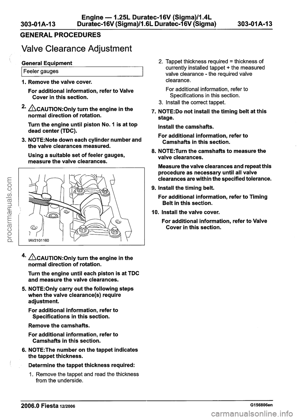
measure the valve clearances.
Measure the valve clearances and repeat this
valve clearance - the required valve
procedure as necessary until all valve
clearances are within the specified tolerance.
9. Install the timing belt.
For additional information, refer to Timing
Belt in this section.
10, Install the valve cover.
For additional information, refer to Valve
Cover in this section.
4m ~CAUTION:O~I~ turn the engine in the
normal direction of rotation.
Turn the engine until each piston is at TDC
and measure the valve clearances.
5. N0TE:Only carry out the following steps
when the valve
clearance(s) require
adjustment.
For additional information, refer to
Specifications in this section.
Remove the camshafts.
For additional information, refer to
Camshafts in this section.
6. N0TE:The number on the tappet indicates
the tappet thickness.
Determine the tappet thickness required:
1. Remove the tappet and read the thickness
from the underside.
2006.0 Fiesta 1212006 GI 56806en
procarmanuals.com
Page 504 of 1226
Engine - I .25L Duratec-1 6V (Sigma)llm4L
303-01 A-28 Duratec-1 6V (Sigma)llm6L Duratec-1 6V (Sigma) 303-01 A-28
IN-VEHICLE REPAIR
Valve Cover(21 141 0)
Materials 4. Remove the valve cover. (. ,
Name Specification
I Silicone grease IESE-MlC171-AA I
Removal
A WARNING:Do not smoke or carry lighted
tobacco or open flame of any type when
working on or near any fuel related
components. Highly flammable mixtures
are always present and may ignite. Failure
to follow these instructions may result
in
personal injury.
1. Disconnect the battery ground cable. For
additional information, refer to
Section
414-01 [Battery, Mounting and
Cables].
2. Remove the air cleaner. For additional
information, refer to Section
303-12 [Intake
Air Distribution and Filtering].
3. Disconnect the spark plug electrical
connectors and detach the wires from the
valve cover.
Installation
1. N0TE:Check the valve cover gasket for
damage and install a new valve cover gasket
if necessary.
N0TE:lnstall the stud bolts to positions 5 and 6.
Install the valve cover.
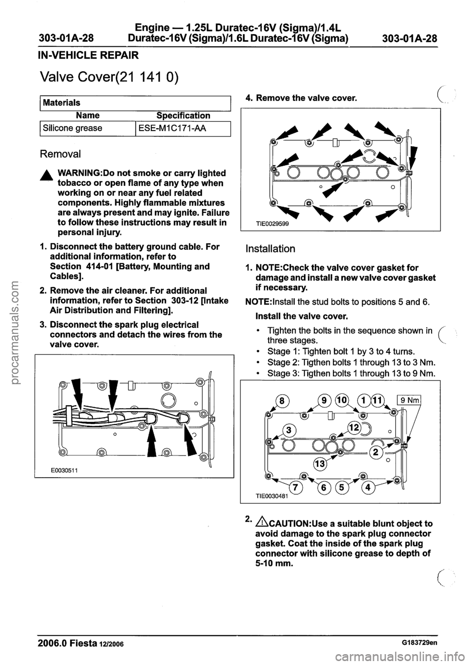
Tighten the bolts in the sequence shown in
three stages.
Stage 1: Tighten bolt 1 by 3 to 4 turns.
Stage 2: Tigthen bolts 1 through 13 to 3 Nm.
Stage 3: Tigthen bolts 1 through 13 to 9 Nm.
2m ACAUTION:~~~ a suitable blunt object to
avoid damage to the spark plug connector
gasket. Coat the inside of the spark plug
connector with silicone grease to depth of
5-10 mm.
- - --
2006.0 Fiesta 1212006 GI 83729en
procarmanuals.com
Page 523 of 1226
Engine - 1.25L Duratec-1 6V (Sigma)llI4L
303-0 1 A-47 Duratec-1 6V (Sigma)/l .6L Duratec-1 6V (Sigma) 303-01 A-47
IN-VEHICLE REPAIR
Exhaust Manifold(21 187 0)
i Special Tool(s1 2. Remove the air cleaner.
--
Adapter for 303-290A
303-290-01 (21 -1 40-01
)
Adapter for 303-290A
303-290-02 (21 -1 40-02)
21 14002
General Equipment
21 14003
I Exhaust wrap I
Adapter for 303-290A
303-290-03A (21
-1 40-03A)
Removal
For additional information, refer to: Air
Cleaner - 1.25L Duratec-1 6V (Sigma)llm4L
Duratec-1 6V (Sigma)ll .6L Duratec-1 6V
(Sigma) (303-12 Intake Air Distribution and
Filtering, Removal and Installation).
3. Raise and support the vehicle.
For additional information, refer to: Lifting
(100-02 Jacking and Lifting, Description
and Operation).
4m ACAUTION:~~~~ bending of the exhaust
flexible pipe may cause damage resulting in
failure.
Support the exhaust flexible pipe with a
support wrap or
suitable splint.
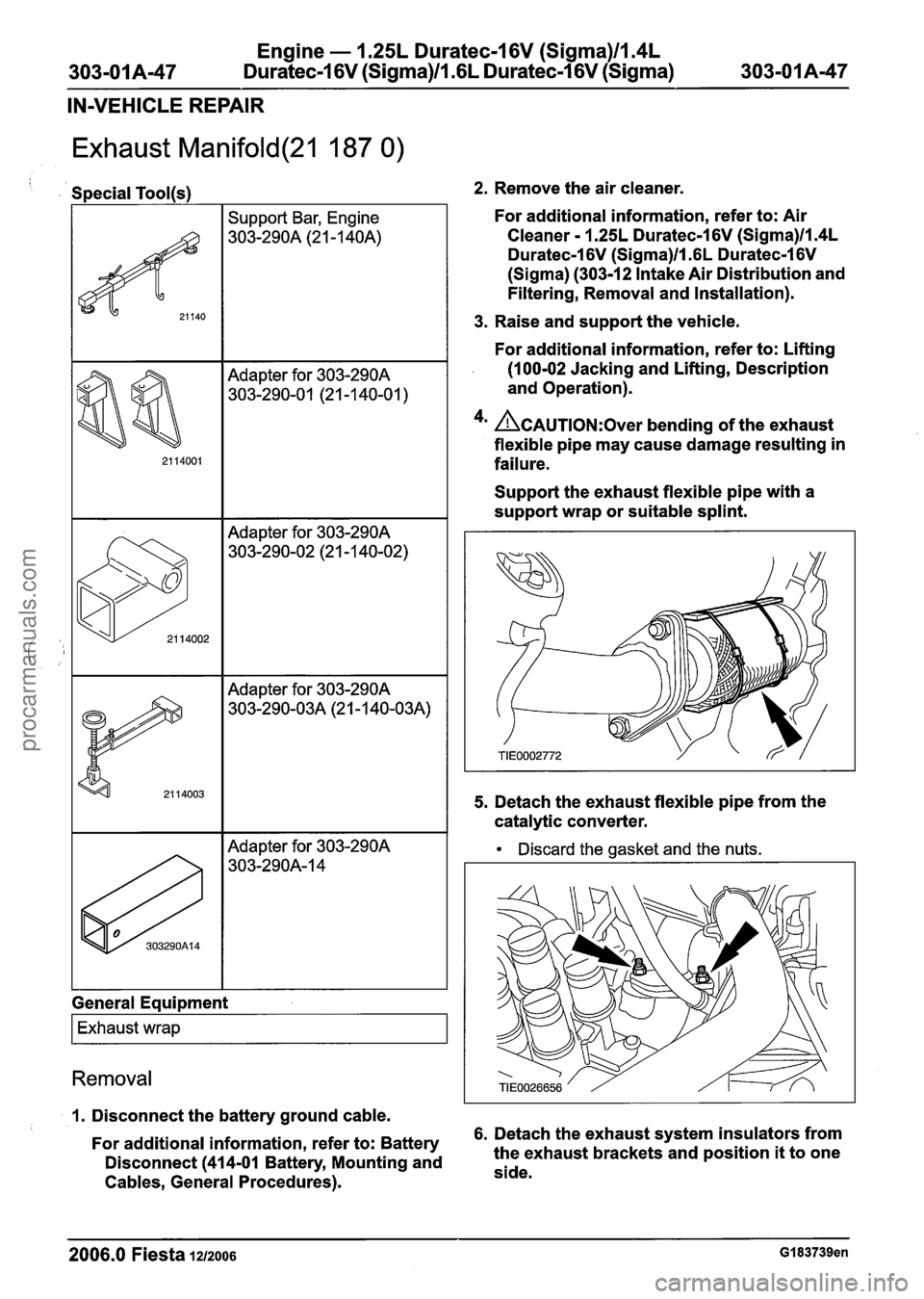
5. Detach the exhaust flexible pipe from the
catalytic converter.
Discard the gasket and the nuts.
1. Disconnect the battery ground cable. - -
For additional information, refer to: Battery 6.
Detach the exhaust system insulators from
Disconnect
(414-01 Battery, Mounting and the
exhaust brackets and position it to one
Cables, General Procedures). side.
2006.0 Fiesta 12/2006 GI 83739en
procarmanuals.com
Page 530 of 1226
Engine - I .25L Duratec-1 6V (Sigma)llI4L
303-01 A-54 Duratec-1 6V (Sigma)/l .6L Duratec-1 6V (Sigma)
303-01 A-54
IN-VEHICLE REPAIR
Cylinder Head(21 163 0)
1 I Socket, Cylinder Head Bolts I
Discard the gasket and the nuts. (
Removerllnstaller, Hose
Clamp
303-397 (24-003)
I 24003 1 1 5. Raise and support the vehicle.
Removal
I I 1 For additional information, refer to: Lifting
(100-02 Jacking and Lifting, Description
1. Release the fuel system pressure.
Materials
For
additional information, refer to: Fuel
System Pressure Release (31 0-00 Fuel
System - General Information, General
Procedures). and
Operation).
2. Drain the
cooling system.
For
additional information, refer to: Cooling
System Draining, Filling and Bleeding
(303-03 Engine Cooling - 1.4L
Duratorq-TDCi (DV) Diesel, General 7. Remove the exhaust manifold lower heat
Procedures). shield left-hand retaining bolts.
3. Remove the camshaft.
Name
Specification
6. Using a suitable splint or wrap support the
For
additional information, refer to:
Camshafts
(303-01 Engine - 1.25L
Duratec-1 6V (Sigma)ll.4L Duratec-1 6V
(Sigma)ll.GL Duratec-1 6V (Sigma),
In-vehicle Repair).
Engine oil I WSS-M2C912-A1
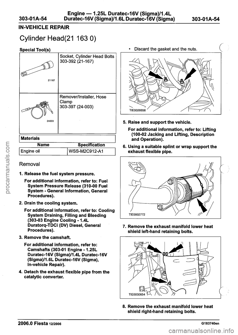
4. Detach the exhaust flexible pipe from the
catalytic converter. exhaust
flexible pipe.
8. Remove the exhaust manifold lower heat
shield right-hand retaining bolts.
2006.0 Fiesta 1212006 GI 83740en
procarmanuals.com
Page 546 of 1226
Engine - 1.25L Duratec-1 6V (Sigma)ll.4L
303-01 A-70 Duratec-I 6V (Sigma)lll6L Duratec-1 6V (Sigma) 303-01 A-70
REMOVAL
Engine
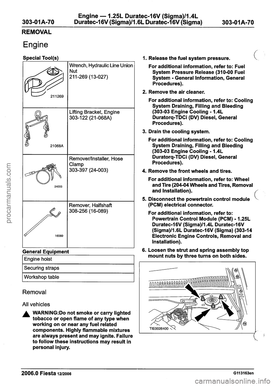
Special Tool(s)
I I Removerllnstaller, Hose
622
General Eaui~ment
Wrench, Hydraulic Line Union
!:!-269 ( 1 3-027)
I Engine hoist I
I Securing straps I
I Workshop table I
Removal
All vehicles
A WARNING:Do not smoke or carry lighted
tobacco or open flame of any type when
working on or near any fuel related
components. Highly flammable mixtures
are always present and may ignite. Failure
to follow these instructions may result in
personal injury.
1. Release the fuel system pressure.
For additional information, refer to: Fuel
System Pressure Release (31 0-00 Fuel
System
- General Information, General
Procedures).
2. Remove the air cleaner.
For additional information, refer to: Cooling
System Draining, Filling and Bleeding
(303-03 Engine Cooling - 1.4L
Duratorq-TDCi (DV) Diesel, General
Procedures).
3. Drain the cooling system.
For additional information, refer to: Cooling
System Draining, Filling and Bleeding
(303-03 Engine Cooling - 1.4L
Duratorq-TDCi (DV) Diesel, General
Procedures).
4. Remove the front wheels and tires.
For additional information, refer to: Wheel
and Tire (204-04 Wheels and Tires, Removal
and Installation).
5. Disconnect the powertrain control module
(PCM) electrical connector.
For additional information, refer to:
Powertrain Control Module (PCM)
- 1.25L
Duratec-1 6V (Sigma)ll.4L Duratec-1 6V
(Sigma)ll .6L Duratec-1 6V (Sigma) (303-1 4
Electronic Engine Controls, Removal and
Installation).
6. Loosen the strut and spring assembly top
mount nuts by three turns on both sides.
2006.0 Fiesta 1212006 GII 31 63en
procarmanuals.com
Page 552 of 1226
Engine - 1.25L Duratec-1 6V (Sigma)ll.4L
303-01 A-76 Duratec-1 6V (Sigma)lll6L Duratec-1 6V (Sigma) 303-01 A-76
REMOVAL
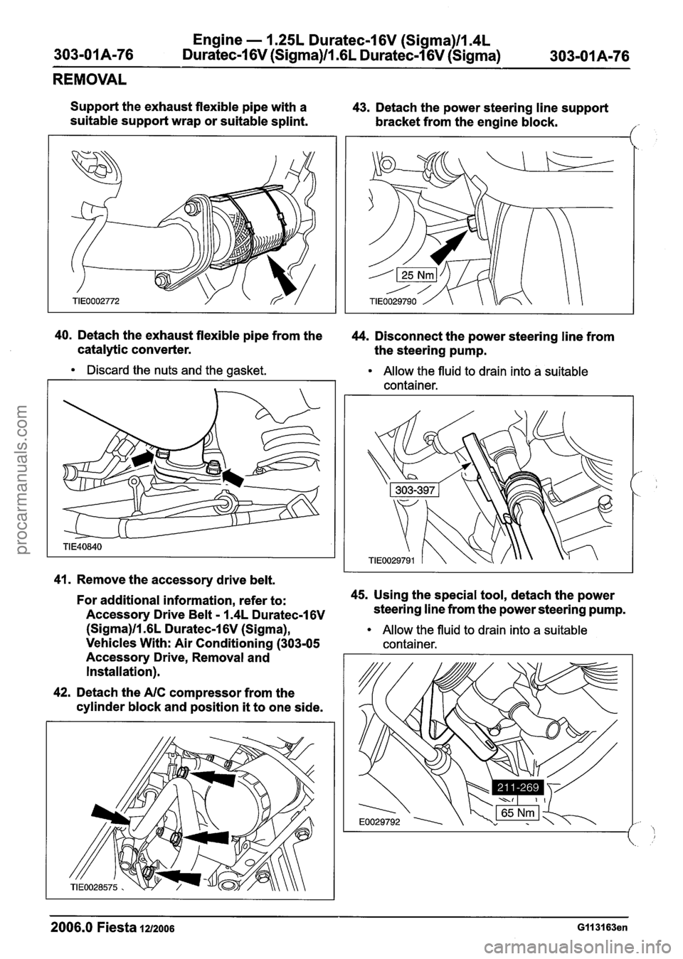
Support the exhaust flexible pipe with a
suitable support wrap or suitable splint. 43.
Detach the power steering line support
bracket from the engine block.
/' -
40. Detach the exhaust flexible pipe from the
44. Disconnect the power steering line from
catalytic converter. the steering pump.
Discard the nuts and the gasket.
Allow the fluid to drain into a suitable
container.
41. Remove the accessory drive belt.
For additional information, refer to: 45.
Using the special tool, detach the power
Accessory Drive Belt
- I .4L Duratec-16V steering line from the power steering pump.
(Sigma)ll.GL Duratec-1 6V (Sigma), Allow the fluid to drain into a suitable
Vehicles With: Air Conditioning (303-05 container.
Accessory Drive, Removal and
Installation).
42. Detach the
AIC compressor from the
cylinder block and position
it to one side.
2006.0 Fiesta 1212006 GII 31 63en
procarmanuals.com
Page 553 of 1226
Engine - 1.25L Duratec-1 6V (Sigma)ll.4L
303-01 A-77 Duratec-1 6V (Sigma)ll .6L
Duratec-1 6V (Sigma) 303-01 A-77
REMOVAL
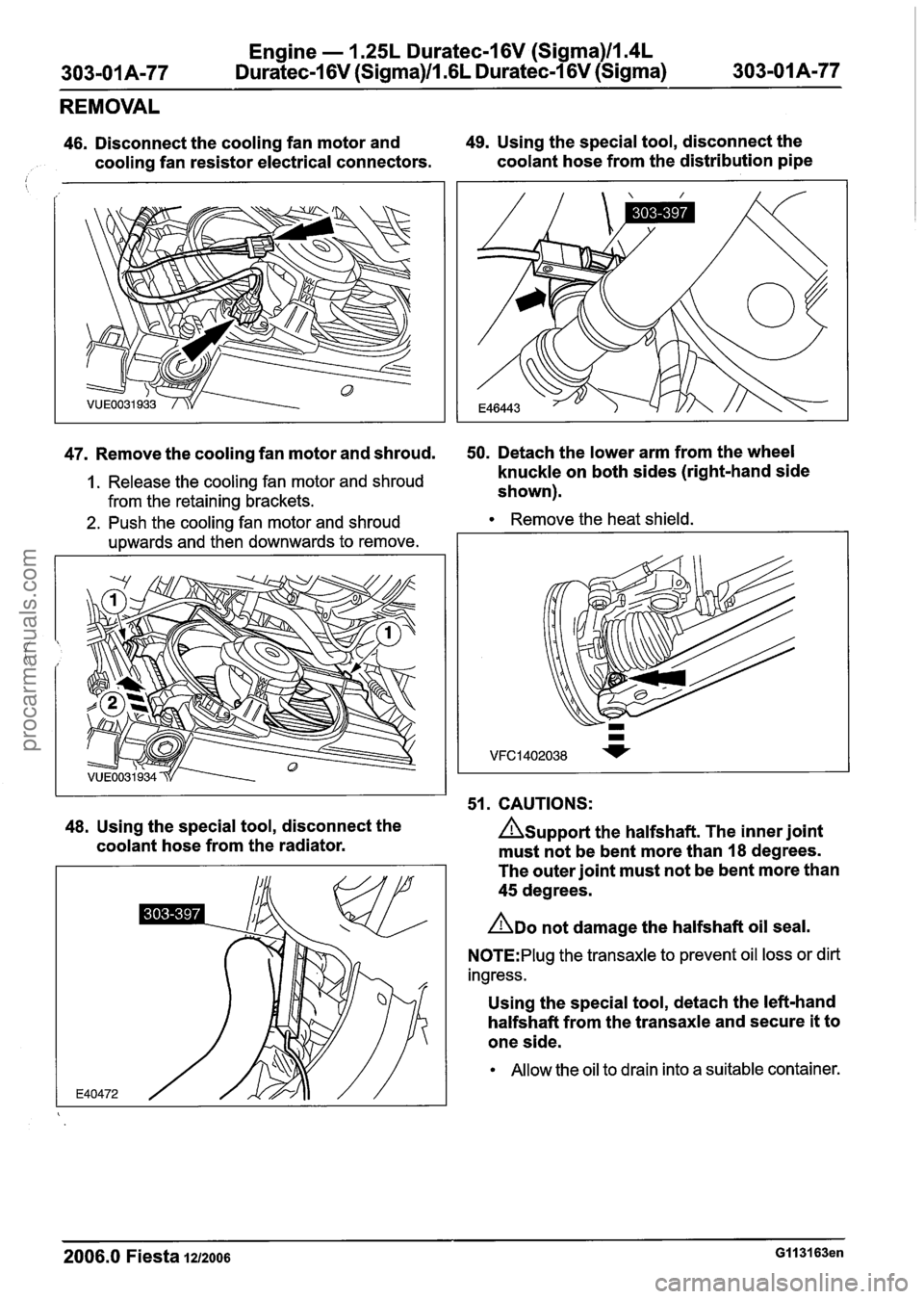
46. Disconnect the cooling fan motor and 49. Using the special tool, disconnect the
cooling fan resistor electrical connectors. coolant
hose from the distribution pipe
47. Remove the cooling fan motor and shroud. 50. Detach the lower arm from the wheel -
1. Release the cooling fan motor and shroud knuckle on both sides (right-hand side
from the retaining brackets. shown).
2. Push the coolingfan motor and shroud Remove the heat shield.
upwards and then downwards to remove.
I I 51. CAUTIONS:
48. Using the special tool, disconnect the Asupport the halfshaft. The inner joint
coolant hose from the radiator.
must not be bent more than
18 degrees.
The outer joint must not be bent more than
45 degrees.
ADO not damage the halfshaft oil seal.
N0TE:PIug the transaxle to prevent oil loss or dirt
ingress.
Using the special tool, detach the left-hand
halfshaft from the transaxle and secure it
to
one side.
Allow the oil to drain into a suitable container.
2006.0 Fiesta 1212006 GI 131 63en
procarmanuals.com
Page 554 of 1226
Engine - 1.25L Duratec-1 6V (Sigma)ll.4L
303-01A-78 Duratec-1 6V (Sigma)/l .6L Duratec-1 6V (Sigma) 303=01 A178
REMOVAL
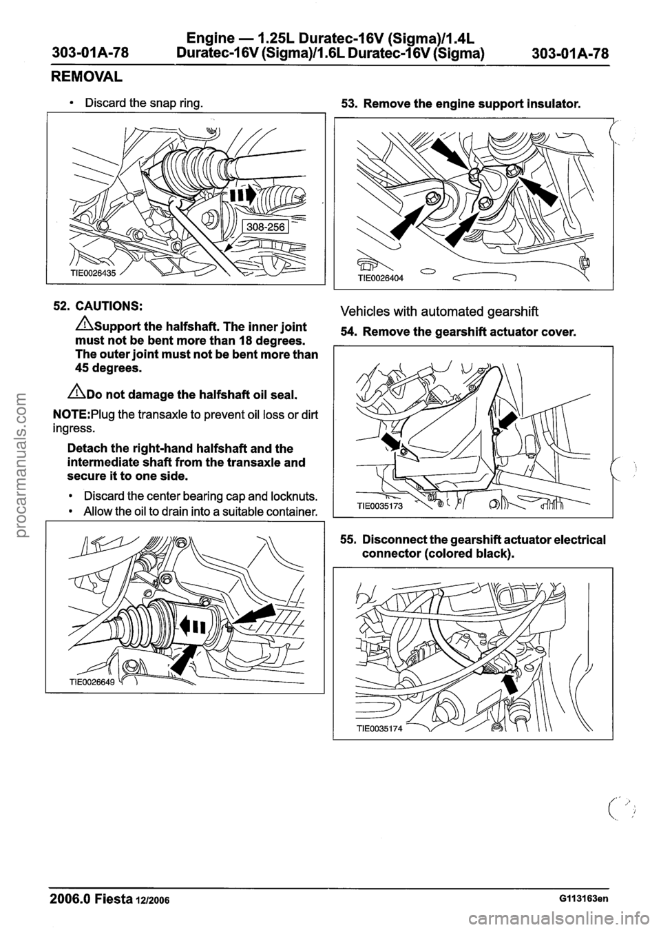
Discard the snap ring.
53. Remove the engine support insulator.
52. CAUTIONS: Vehicles with automated gearshift
AUPPO~~ the halfshaft. The inner joint 54. Remove the gearshift actuator cover. must not be bent more than 18 degrees.
The outer joint must not be bent more than
45 degrees.
ADO not damage the halfshaft oil seal.
N0TE:Plug the transaxle to prevent oil loss or dirt
ingress.
Detach the right-hand halfshaft and the
intermediate shaft from the transaxle and
secure
it to one side.
Discard the center bearing cap and locknuts.
Allow the oil to drain into a suitable container.
55.
Disconnect the gearshift actuator electrical
connector (colored black).
2006.0 Fiesta 1212006 GII 31 63en
procarmanuals.com
Page 556 of 1226
Engine - 1.25L Duratec-1 6V (Sigma)ll14L
Duratec-I 6V (Sigma)ll16L Duratec-1 6V (Sigma)
REMOVAL
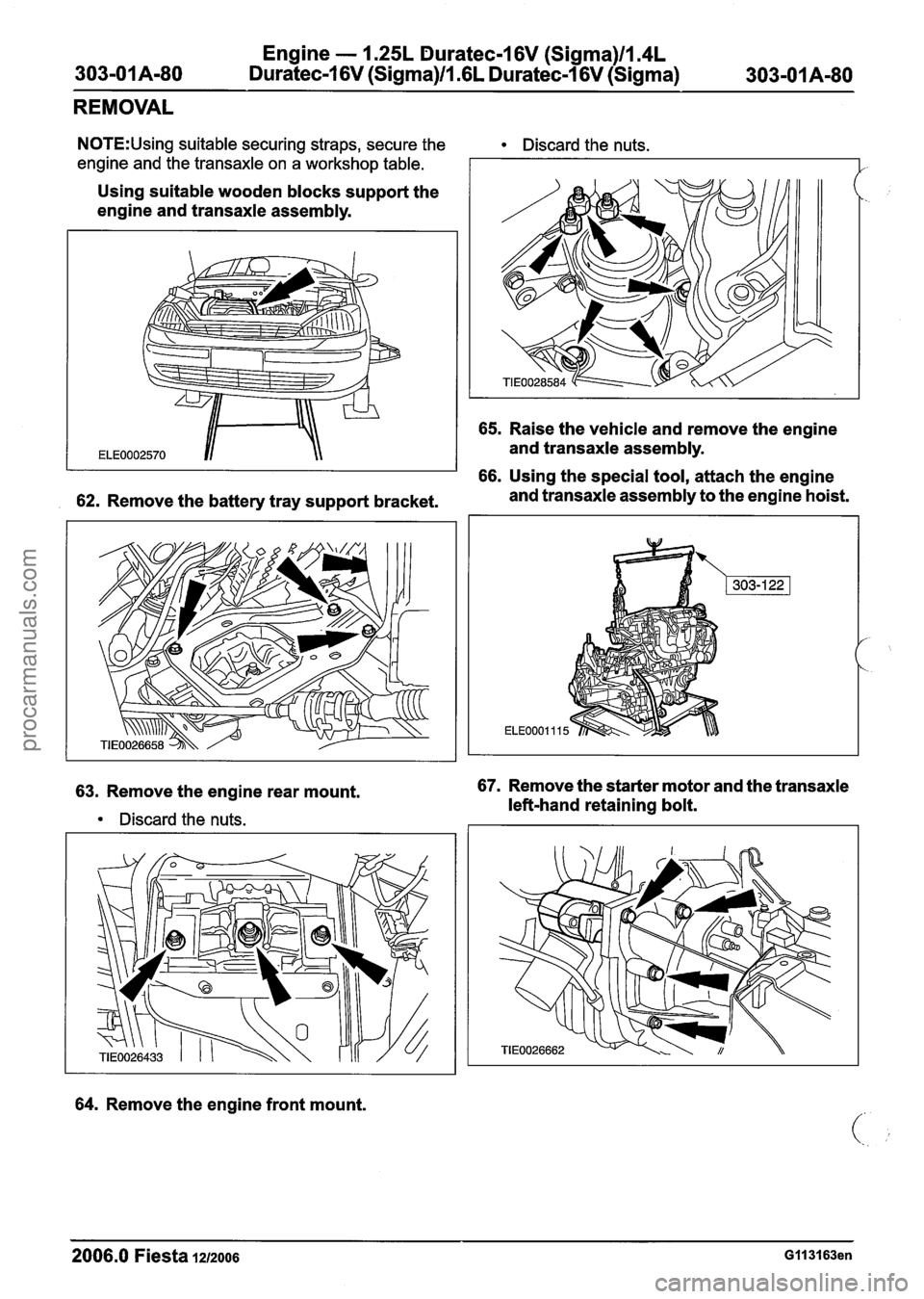
N0TE:Using suitable securing straps, secure the Discard the nuts.
engine and the transaxle on a workshop table.
Using suitable wooden blocks support the
engine and transaxle assembly.
65. Raise the vehicle and remove the engine
and transaxle assembly.
66. Using the special tool, attach the engine
62. Remove the battery tray support bracket. and transaxle
assembly to the engine hoist.
63. Remove the engine rear mount.
Discard the nuts.
64. Remove the engine front mount.
67. Remove the starter motor and the transaxle
left-hand retaining bolt.
-
2006.0 Fiesta 1212006 G113163en
procarmanuals.com
Page 558 of 1226
Engine - 1.25L Duratec-1 6V (Sigma)ll.4L
303-0 I Am82 Duratec-1 6V (Sigma)ll .6L Duratec-1 6V (Sigma)
303-01 Am82
REMOVAL
Lifting Bracket, Engine
303-1 22 (21 -068A)
Engine - Vehicles With: Automatic Transaxle
Special Tool(s) present and may ignite. Failure to follow (.
2. Remove the air cleaner.
622
For additional information, refer to: Air
Cleaner - 1.25L Duratec-1 6V (Sigma)ll.4L
Duratec-1 6V (Sigma)/l .6L Duratec-1 6V
(Sigma) (303-12 Intake Air Distribution and
Filtering, Removal and Installation).
I I 1 3. Drain the cooling system.
Wrench, Hydraulic Line Union
"-269 (13-027)
I I Remover/lnstaller, Hose I
these instructions may result in personal
injury.
1. Release the fuel system pressure.
For
additional information, refer to: Fuel
System Pressure Release (31 0-00 Fuel
System - General Information, General
Procedures).
General Eaui~ment
I Engine hoist I
I Securing straps I
I Workshop table I
All vehicles
WARNINGS:
A Refer to the Material Safety Data Sheets
for the Automatic Transmission
Fluid
E-AW. Failure to follow this instruction may
result in personal injury. Certain
Transmission and Power Steering fluids
supplied to Ford contain additives which
may cause skin irritation or other skin
reactions after contact.
For
additional information, refer to: Health
and Safety Precautions (1 00-00 General
Information, Description and Operation).
See
- Transmission Fluids.
A Do not smoke or carry lighted tobacco or
open flame of any type when working on
or near any
fuel related components.
Highly flammable vapors are always
For additional information, refer to: Cooling
System Draining, Filling and Bleeding -
1.25L Duratec-1 6V (Sigma)ll.4L
Duratec-1 6V (Sigma)ll .6L Duratec-1 6V
(Sigma)llm3L Duratec-8V (Rocam) (303-03A,
General Procedures). ,'
4. Remove the front wheels and tires. C'
For additional information, refer to: Wheel
and Tire (204-04 Wheels and Tires, Removal
and Installation).
5. Disconnect the powertrain control module
(PCM) electrical connector.
For
additional information, refer to:
Powertrain
Control Module (PCM) - 1.25L
Duratec-1 6V (Sigma)ll.4L Duratec-1 6V
(Sigma)ll .6L Duratec-1 6V (Sigma) (303-14
Electronic Engine Controls, Removal and
Installation).
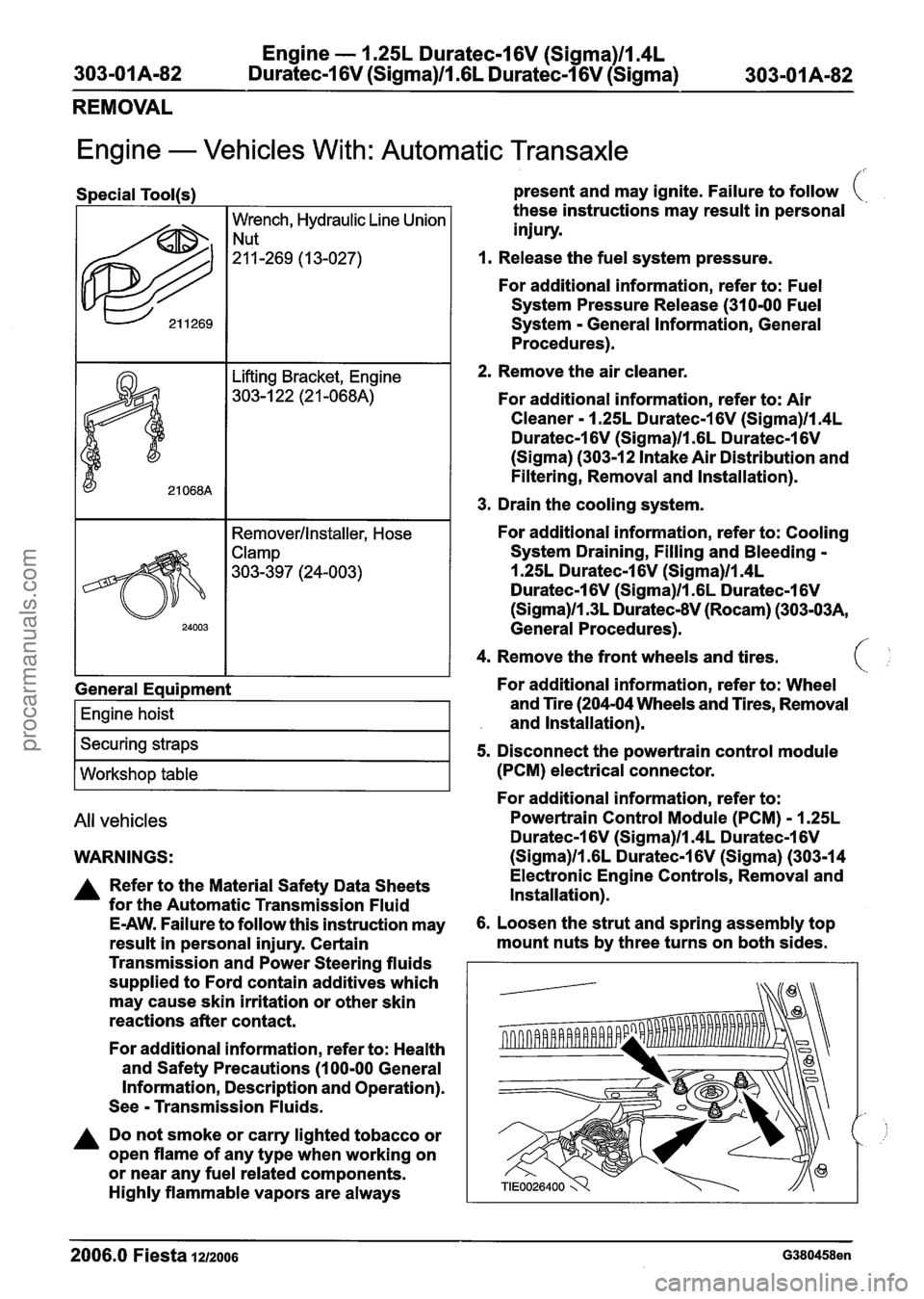
6. Loosen the strut and spring assembly top
mount nuts by three turns on both sides.
--
2006.0 Fiesta 1212006 G380458en
procarmanuals.com