engine coolant FORD FIESTA 2007 Workshop Manual
[x] Cancel search | Manufacturer: FORD, Model Year: 2007, Model line: FIESTA, Model: FORD FIESTA 2007Pages: 1226, PDF Size: 61.26 MB
Page 941 of 1226
303-1 4-1 7 Electronic Engine Controls 303-1 4-1 7
DIAGNOSIS AND TESTING
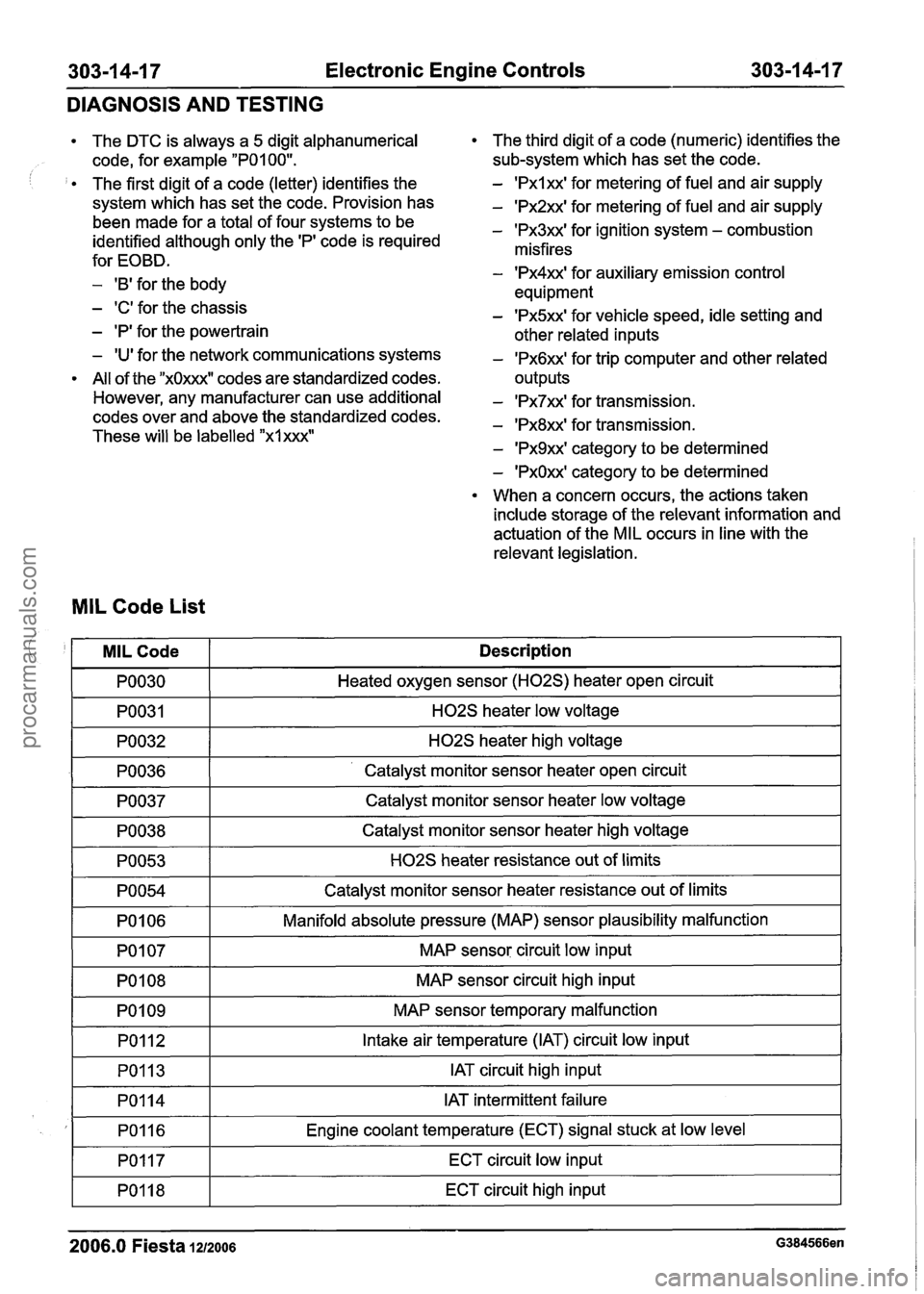
The DTC is always a 5 digit alphanumerical
code, for example
"POI 00".
The first digit of a code (letter) identifies the
system which has set the code. Provision has
been made for a total of four systems to be
identified although only the
'PI code is required
for EOBD.
- 'B' for the body
- 'C' for the chassis
- 'P' for the powertrain
- 'U' for the network communications systems
All of the
"xOxxxW codes are standardized codes.
However, any manufacturer can use additional
codes over and above the standardized codes.
These will be labelled
"xlxxx"
The third digit of a code (numeric) identifies the
sub-system which has set the code.
- 'Pxlxx' for metering of fuel and air supply
- 'Px2xx' for metering of fuel and air supply
- 'Px3xx' for ignition system - combustion
misfires
- 'Px4xx' for auxiliary emission control
equipment
- 'Px5xx' for vehicle speed, idle setting and
other related inputs
- 'Px6xx' for trip computer and other related
outputs
- 'Px7xx' for transmission.
- 'Px8xx' for transmission.
- 'Px9xx' category to be determined
- 'PxOxx' category to be determined
When a concern occurs, the actions taken
include storage of the relevant information and
actuation of the MIL occurs in line with the
relevant legislation.
MIL Code List
I PO030 I Heated oxygen sensor (H02S) heater open circuit I
! '
-1 H02S heater low voltage I
I PO032 I H02S heater high voltage I
MILCode
PO036 1- ' Catalyst monitor sensor heater open circuit I
Description
PO037
I PO054 I Catalyst monitor sensor heater resistance out of limits I
Catalyst monitor sensor heater low voltage
PO038
PO053
I PO106 I Manifold absolute pressure (MAP) sensor plausibility malfunction I
-
Catalyst monitor sensor heater high voltage
H02S heater resistance out of limits
I PO107 I MAP sensor circuit low input I
PO108
PO1 09 MAP sensor
circuit high input
MAP sensor temporary malfunction
PO1 12
PO113
I PO117 I ECT circuit low input I
Intake air temperature (IAT) circuit low input
IAT circuit high input
I
2006.0 Fiesta 1212006 G384566en
PO114
PO1 16
PO118
IAT intermittent failure
Engine coolant temperature (ECT) signal stuck at low level
ECT circuit high input
procarmanuals.com
Page 959 of 1226
303-1 4-35 Electronic Engine Controls 303-1 4-35
REMOVAL AND INSTALLATION
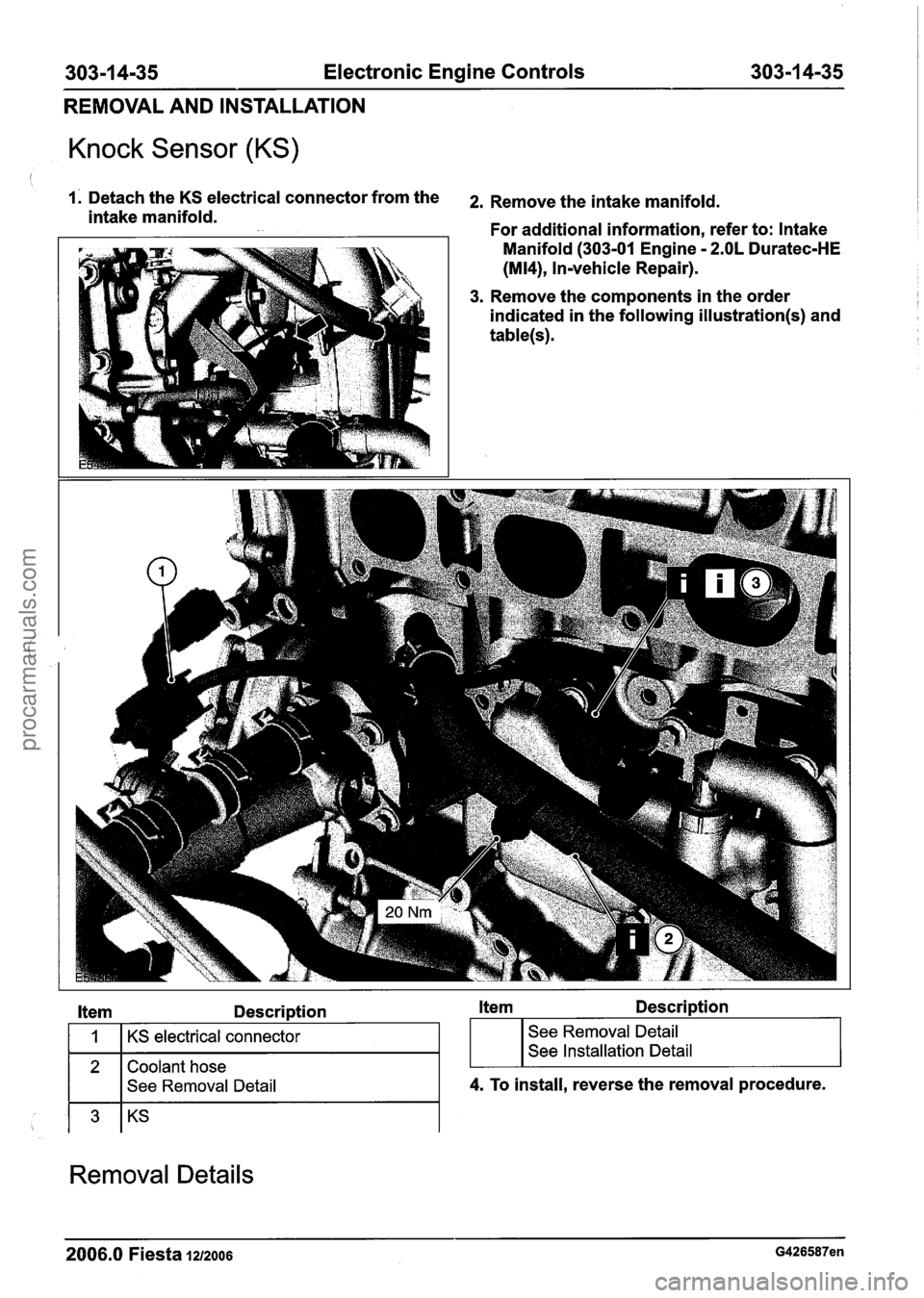
Knock Sensor (KS)
1. Detach the KS electrical connector from the 2, Remove the intake manifold. intake manifold.
For additional information, refer to: Intake
1 Manifold (303-01 Engine - 2.OL Duratec-HE
(M14), Invehicle Repair).
3. Remove the components in the order
indicated in the following
illustration(s) and
table(s).
Item Description Item Description
2 Coolant hose
I I See Removal Detail
1
I I
4. To install, reverse the removal procedure.
KS electrical connector
Removal Details
; I I
See Removal Detail
See Installation Detail
2006.0 Fiesta 1212006 G426587en
procarmanuals.com
Page 960 of 1226

303-1 4-36 Electronic Engine Controls 303-1 4-36
REMOVAL AND INSTALLATION
Ifem 2 Coolant hose kern 3 KS
I. Detach the coolant hose from the coolant N0TE:Make a note of the position of the KS and
hose retaining clip and position it to one
when installed.
make sure
it is positioned in the same position
.
side.
Installation Details
ltem 3 KS
NOTE: Prior to installing the KS, clean the engine
block and KS mating surfaces.
N0TE:Make sure the KS is installed in the same
position as removed.
(I.
2006.0 Fiesta 1212006 G426587en
procarmanuals.com
Page 991 of 1226
Automatic TransmissionlTransaxle -
Vehicles With: 4-Speed Automatic
307-01 -31 Transmission (AW81-40) 307-01 -31
DESCRIPTION AND OPERATION
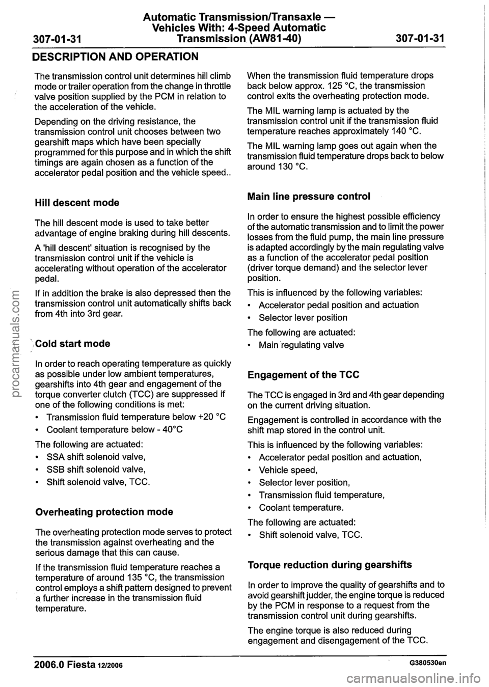
The transmission control unit determines hill climb
mode or trailer operation from the change in throttle
; valve position supplied by the PCM in relation to
the acceleration of the vehicle.
Depending on the driving resistance, the
transmission control unit chooses between two
gearshift maps which have been specially
programmed for this purpose and in which the shift
timings are again chosen as a function of the
accelerator pedal position and the vehicle speed..
Hill descent mode
The hill descent mode is used to take better
advantage of engine braking during hill descents.
A 'hill descent' situation is recognised by the
transmission control unit if the vehicle is
accelerating without operation of the accelerator
pedal.
If in addition the brake is also depressed then the
transmission control unit automatically shifts back
from 4th into 3rd gear.
( ' Cold start mode
In order to reach operating temperature as quickly
as possible under low ambient temperatures,
gearshifts into 4th gear and engagement of the
torque converter clutch (TCC) are suppressed if
one of the following conditions is met:
Transmission fluid temperature below +20 "C
Coolant temperature below - 40°C
The following are actuated: SSA shift solenoid valve,
SSB shift solenoid valve,
Shift solenoid valve, TCC.
Overheating protection mode
The overheating protection mode serves to protect
the transmission against overheating and the
serious damage that this can cause.
If the transmission fluid temperature reaches a
temperature of around 135
"C, the transmission
control employs a shift pattern designed to prevent
a further increase in the transmission fluid
temperature. When
the transmission fluid temperature drops
back below approx. 125
"C, the transmission
control exits the overheating protection mode.
The MIL warning lamp is actuated by the
transmission control unit if the transmission fluid
temperature reaches approximately 140
"C.
The MIL warning lamp goes out again when the
transmission fluid temperature drops back to below
around 130
"C.
Main line pressure control
In order to ensure the highest possible efficiency
of the automatic transmission and to limit the power
losses from the fluid pump, the main line pressure
is adapted accordingly by the main regulating valve
as a function of the accelerator pedal position
(driver torque demand) and the selector lever
position.
This is influenced by the following variables:
Accelerator pedal position and actuation
Selector lever position
The following are actuated:
Main 'regulating valve
Engagement of the TCC
The TCC is engaged in 3rd and 4th gear depending
on the current driving situation.
Engagement is controlled in accordance with the
shift map stored in the control unit.
This is influenced by the following variables:
Accelerator pedal position and actuation,
Vehicle speed,
Selector lever position,
Transmission fluid temperature,
Coolant temperature.
The following are actuated:
Shift solenoid valve, TCC.
Torque reduction during gearshifts
In order to improve the quality of gearshifts and to
avoid gearshift judder, the engine torque is reduced
by the PCM in response to a request from the
transmission control unit during gearshifts.
The engine torque is also reduced during
engagement and disengagement of the TCC.
2006.0 Fiesta 1212006 G380530en
procarmanuals.com
Page 995 of 1226
Automatic Transmission/Transaxle -
Vehicles With: 4Speed Automatic
307-01 -35 Transmission (AW81-40) 307-01 -35
DESCRIPTION AND OPERATION
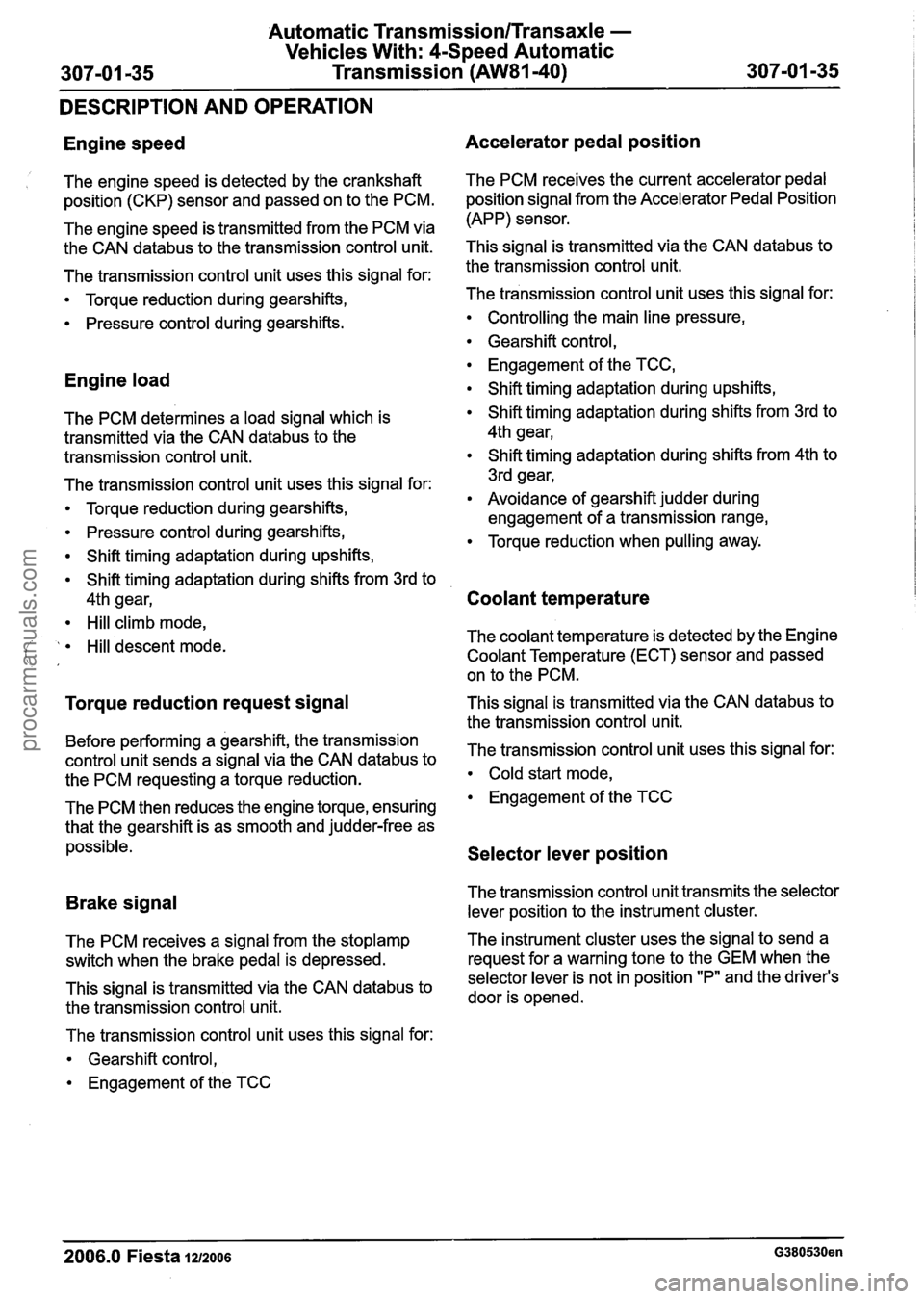
Engine speed
1 The engine speed is detected by the crankshaft
position (CKP) sensor and passed on to the PCM.
The engine speed is transmitted from the PCM via
the CAN
databus to the transmission control unit.
The transmission control unit uses this signal for:
Torque reduction during gearshifts,
Pressure control during gearshifts.
Engine load
The PCM determines a load signal which is
transmitted via the CAN
databus to the
transmission control unit.
The transmission control unit uses this signal for:
Torque reduction during gearshifts,
Pressure control during gearshifts,
Shift timing adaptation during upshifts,
Shift timing adaptation during shifts from 3rd to
4th gear,
Hill climb mode,
( ' Hill descent mode. ' ,
Torque reduction request signal
Before performing a gearshift, the transmission
control unit sends a signal via the CAN
databus to
the PCM requesting a torque reduction.
The PCM then reduces the engine torque, ensuring
that the gearshift is as smooth and judder-free as
possible.
Brake signal
The PCM receives a signal from the stoplamp
switch when the brake pedal is depressed.
This signal is transmitted via the CAN
databus to
the transmission control unit.
The transmission control unit uses this signal for:
Gearshift control,
Engagement of the TCC
Accelerator pedal position
The PCM receives the current accelerator pedal
position signal from the Accelerator Pedal Position
(APP) sensor.
This signal is transmitted via the CAN
databus to
the transmission control unit.
The transmission control unit uses this signal for:
Controlling the main line pressure,
Gearshift control,
Engagement of the TCC,
Shift timing adaptation during upshifts,
Shift timing adaptation during shifts from 3rd to
4th gear,
Shift timing adaptation during shifts from 4th to
3rd gear,
Avoidance of gearshift judder during
engagement of a transmission range,
Torque reduction when pulling away.
Coolant temperature
The coolant temperature is detected by the Engine
Coolant Temperature (ECT) sensor and passed
on to the PCM.
This signal is transmitted via the CAN
databus to
the transmission control unit.
The transmission control unit uses this signal for:
Cold start mode,
Engagement of the TCC
Selector lever position
The transmission control unit transmits the selector
lever position to the instrument cluster.
The instrument cluster uses the signal to send a
request for a warning tone to the GEM when the
selector lever is not in position "P" and the driver's
door is opened.
-
2006.0 Fiesta 1212006 G380530en
procarmanuals.com
Page 1006 of 1226
Automatic Transmission/Transaxle -
Vehicles With: 4Speed Automatic
307-01 -46 Transmission
(AW81-40) 307101 -46
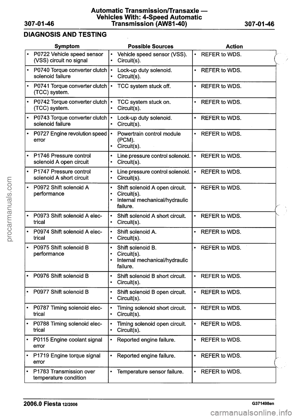
DIAGNOSIS AND TESTING
Symptom Possible Sources Action
PO722 Vehicle speed sensor Vehicle speed sensor (VSS).
1 (vSS) circuit no signal I circuit(+
REFER to WDS.
PO740 Torque converter clutch Lock-up duty solenoid.
solenoid failure
I ~ircuit(s).
REFER to WDS.
REFER to WDS.
PO741 Torque converter clutch
1 (TCC) system.
PO742 Torque converter clutch TCC system stuck on.
I circuit(s).
TCC system stuck off.
REFER to WDS.
PO743 Torque converter clutch Lock-up duty solenoid.
solenoid failure
I circuit(s).
REFER to WDS.
REFER to WDS.
PO727 Engine revolution speed
error
PI 746 Pressure control
I solenoid A open circuit
Powertrain control module
(PCM).
Circuit(s).
I
Line pressure control solenoid.
Circuit(s).
REFER to WDS.
PI 747 Pressure control
solenoid
A short circuit
Line pressure control solenoid.
Circuit(s).
REFER to WDS.
PO972 Shift solenoid A
performance Shift solenoid
A open
circuit.
Circuit(s).
Internal mechanical/hydraulic
failure.
REFER to WDS.
REFER to WDS.
PO974 Shift solenoid A elec- Shift solenoid A.
trical I circuit(!+
PO973 Shift solenoid A elec-
trical
REFER to WDS. Shift solenoid A short circuit.
Circuit(s).
PO975 Shift solenoid B
performance Shift solenoid
B.
Circuit(s).
Internal mechanical/hydraulic
failure.
REFER
to WDS.
PO976 Shift solenoid B Shift solenoid B short circuit.
Circuit(s).
REFER to WDS.
PO977 Shift solenoid B Shift solenoid B open circuit.
Circuit(s).
REFER to WDS.
PO787 Timing solenoid elec- Timing solenoid short circuit.
trical I circuit(s).
REFER to WDS.
REFER to WDS. PO788 Timing solenoid elec-
trical
-- - -
Timing solenoid open circuit.
Circuit(s).
REFER to WDS. PO1 15 Engine coolant signal
error Reported engine failure.
REFER to WDS. I PI 71 9 Engine torque signal
error Reported engine failure.
REFER to WDS. PI 783 Transmission over
temperature condition
2006.0 Fiesta 12/2006 G371498en
Temperature sensor failure.
procarmanuals.com
Page 1117 of 1226
308-03-27 Manual TransmissionlTransaxle 308-03-27
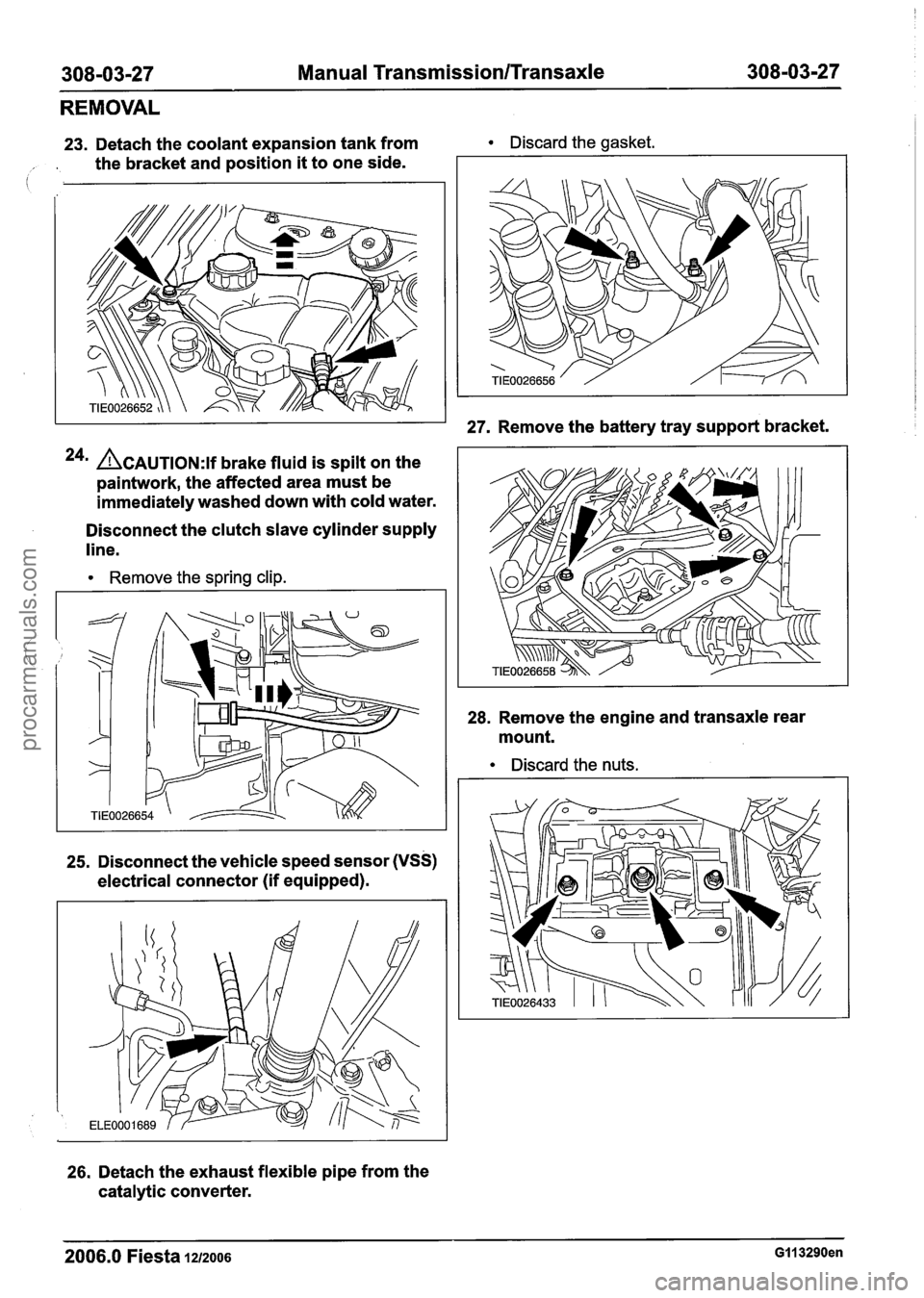
REMOVAL
23. Detach the coolant expansion tank from Discard the gasket.
, . the bracket and position it to one side.
24m ACAUTION:~~ brake fluid is spilt on the
paintwork, the affected area must be
immediately washed down with cold water.
Disconnect the clutch slave cylinder supply
line.
Remove the spring clip.
25. Disconnect the vehicle speed sensor (VSS)
electrical connector (if equipped).
26. Detach the exhaust flexible pipe from the
catalytic converter.
27. Remove the battery tray support bracket.
28. Remove the engine and transaxle rear
mount.
Discard the nuts.
2006.0 Fiesta 1212006 GI1 3290en
procarmanuals.com