engine coolant FORD FIESTA 2007 Workshop Manual
[x] Cancel search | Manufacturer: FORD, Model Year: 2007, Model line: FIESTA, Model: FORD FIESTA 2007Pages: 1226, PDF Size: 61.26 MB
Page 39 of 1226
100-00-23 General Information 100-00-23
DESCRIPTION AND OPERATION
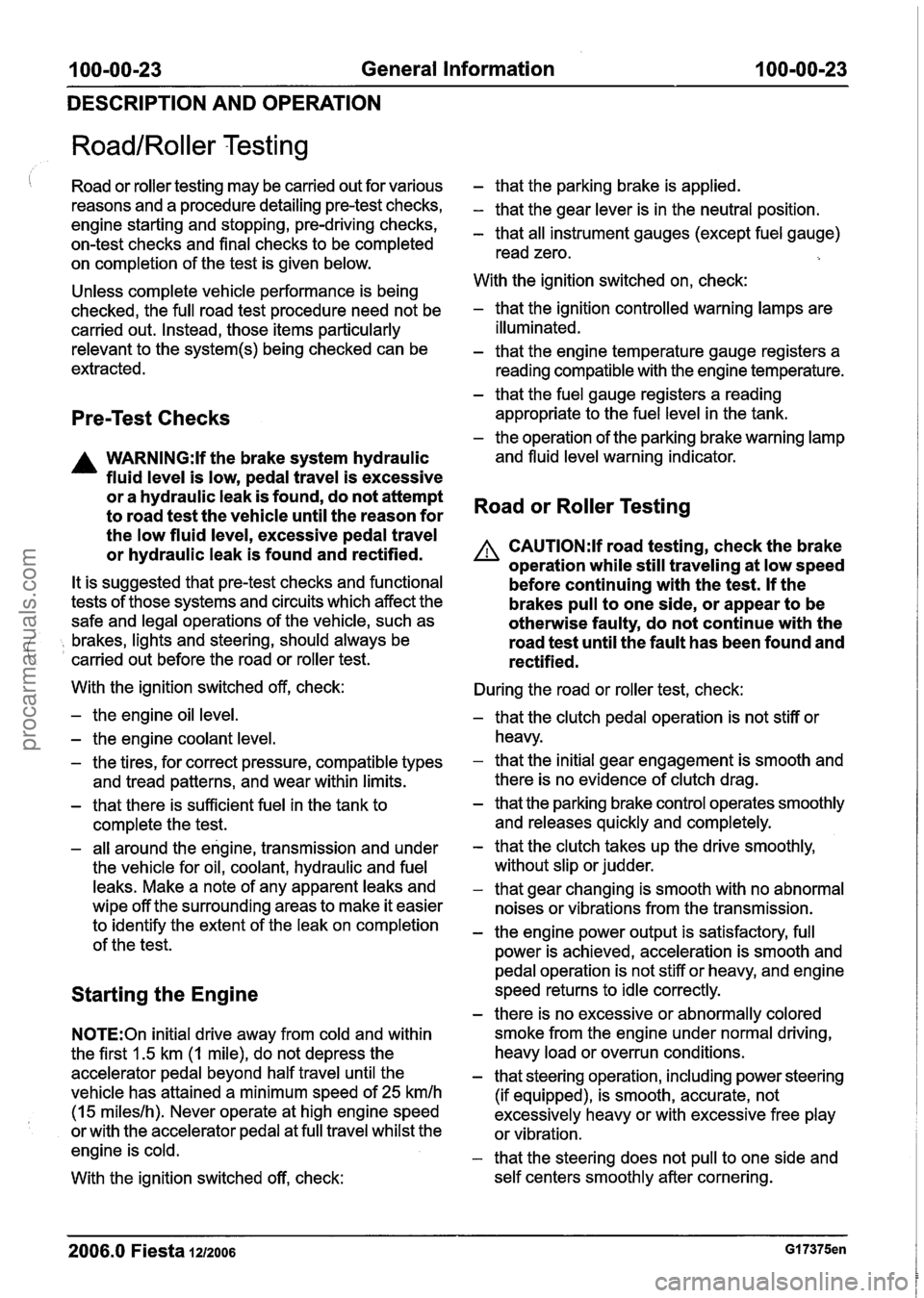
RoadIRoller Testing
I Road or roller testing may be carried out for various
reasons and a procedure detailing pre-test checks,
engine starting and stopping, pre-driving checks,
on-test checks and final checks to be completed
on completion of the test is given below.
Unless complete vehicle performance is being
checked, the full road test procedure need not be
carried out. Instead, those items particularly
relevant to the
system(s) being checked can be
extracted.
Pre-Test Checks
A WARNING:lf the brake system hydraulic
fluid level is low, pedal travel is excessive
or a hydraulic leak is found, do not attempt
to road test the vehicle until the reason for
the low fluid level, excessive pedal travel
or hydraulic leak is found and rectified.
It is suggested that pre-test checks and functional
tests of those systems and circuits which affect the
safe and legal operations of the vehicle, such as
( , brakes, lights and steering, should always be
carried out before the road or roller test.
With the ignition switched off, check:
- the engine oil level.
- the engine coolant level.
- the tires, for correct pressure, compatible types
and tread patterns, and wear within limits.
- that there is sufficient fuel in the tank to
complete the test.
- all around the engine, transmission and under
the vehicle for oil, coolant, hydraulic and fuel
leaks. Make a note of any apparent leaks and
wipe off the surrounding areas to make it easier
to identify the extent of the leak on completion
of the test.
Starting the Engine
N0TE:On initial drive away from cold and within
the first 1.5 km (1 mile), do not depress the
accelerator pedal beyond half travel until the
vehicle has attained a minimum speed of
25 kmlh
(15 mileslh). Never operate at high engine speed
or with the accelerator pedal at full travel whilst the
engine is cold.
With the ignition switched off, check:
- that the parking brake is applied.
- that the gear lever is in the neutral position.
- that all instrument gauges (except fuel gauge)
read zero.
With the ignition switched on, check:
- that the ignition controlled warning lamps are
illuminated.
- that the engine temperature gauge registers a reading compatible with the engine temperature.
- that the fuel gauge registers a reading
appropriate to the fuel level in the tank.
- the operation of the parking brake warning lamp
and fluid level warning indicator.
Road or Roller Testing
A CAUTI0N:lf road testing, check the brake
operation while still traveling at low speed
before continuing with the test. If the
brakes pull to one side, or appear to be
otherwise faulty, do not continue with the
road test until the fault has been found and
rectified.
During the road or roller test, check:
- that the clutch pedal operation is not stiff or
heavy.
- that the initial gear engagement is smooth and
there is no evidence of clutch drag.
- that the parking brake control operates smoothly
and releases quickly and completely.
- that the clutch takes up the drive smoothly,
without slip or judder.
- that gear changing is smooth with no abnormal
noises or vibrations from the transmission.
- the engine power output is satisfactory, full
power is achieved, acceleration is smooth and
pedal operation is not stiff or heavy, and engine
speed returns to idle correctly.
- there is no excessive or abnormally colored
smoke from the engine under normal driving,
heavy load or overrun conditions.
- that steering operation, including power steering
(if equipped), is smooth, accurate, not
excessively heavy or with excessive free play
or vibration.
- that the steering does not pull to one side and
self centers smoothly after cornering.
2006.0 Fiesta 1212006 GI 7375en
procarmanuals.com
Page 426 of 1226
303-004 Engine System - General Information 303-00-4
DIAGNOSIS AND TESTING
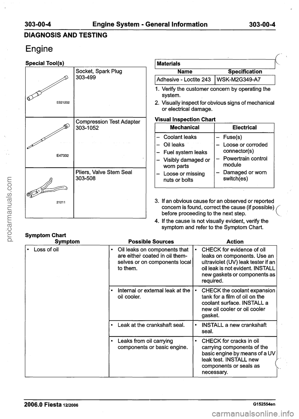
Engine
Special Tool(s)
Socket, Spark Plug
303-499
I Adhesive - Loctite 243 I WSK-M2G349A7 I
Materials
1. Verify the customer concern by operating the
system.
2. Visually inspect for obvious signs of mechanical
or electrical damage.
k.
Name S~ecification
Leaks from oil carrying
components or basic engine.
E47332
&
21211
CHECK for cracks in oil
carrying components of the
basic engine by means of a
leak test. INSTALL new
components or seals as
necessary.
2006.0 Fiesta 1212006 GI 52554en
Compression Test Adapter
303-1 052
Pliers, Valve Stem Seal
303-508
4. If the cause is not visually evident, verify the
symptom and refer to the Symptom Chart.
Symptom Chart Symptom Possible Sources Action
Visual
Inspection Chart
Loss of oil Mechanical
- Coolant
leaks
- Oil leaks
- Fuel system leaks
- Visibly damaged or
worn parts
- Loose or missing
nuts or bolts Electrical
- Fuse(s)
- Loose
or corroded
connector(s)
- Powertrain control
module
- Damaged or worn
switch(es)
Oil leaks on components that
are
eithei coated in oil them-
selves or on components local
to them.
Internal or external leak at the
oil cooler.
Leak at the crankshaft seal.
3. If an obvious cause for an observed or reported
concern is found, correct the cause (if possible)
before proceeding to the next step.
CHECK for evidence of oil
leaks on components. Use an
ultraviolet (UV) leak tester if an
oil leak is not evident, INSTALL
new gaskets or components as
required.
CHECK the coolant expansion
tank for a film of oil on the
coolant surface. INSTALL a
new oil cooler or oil cooler
gasket.
INSTALL a new crankshaft
seal.
procarmanuals.com
Page 429 of 1226
303-00-7 Engine System - General Information 303-00-7
DIAGNOSIS AND TESTING
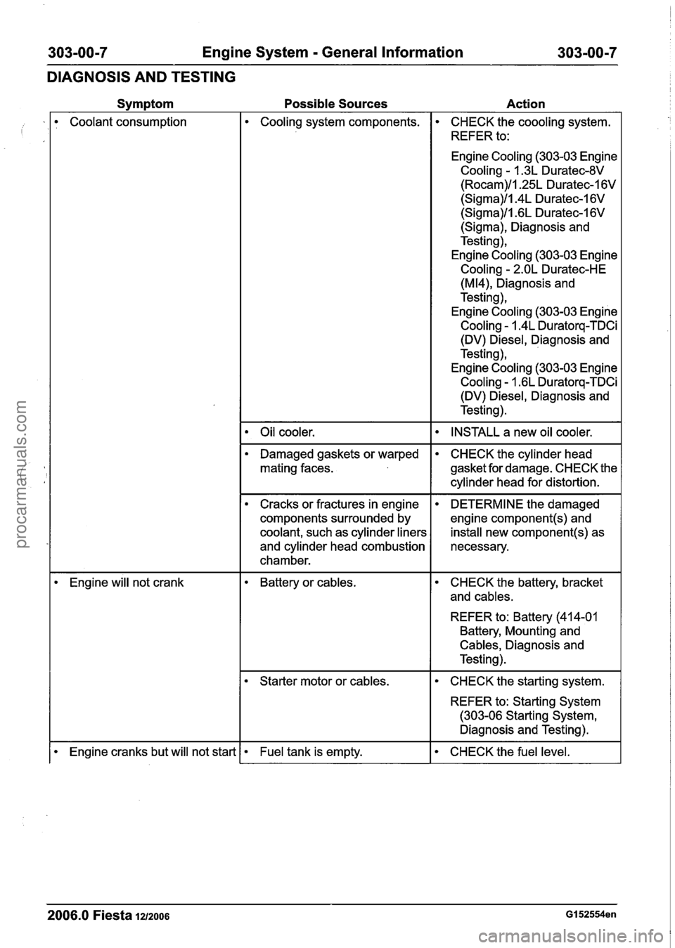
Svm~tom Possible Sources Action
Coolant consumption Cooling system components.
Oil cooler.
CHECK the coooling system.
REFER to:
Engine
Cooling (303-03 Engine
Cooling - 1.3L Duratec-8V
(Rocam)/l.25L Duratec-1 6V
(Sigma)/l.4L Duratec-1 6V
(Sigma)ll .6L Duratec-1 6V
(Sigma), Diagnosis and
Testing),
Engine
Cooling (303-03 Engine
Cooling - 2.OL Duratec-HE
(M14), Diagnosis and
Testing),
Engine
Cooling (303-03 Engine
Cooling - 1.4L Duratorq-TDCi
(DV)
Diesel, Diagnosis and
Testing),
Engine
Cooling (303-03 Engine
Cooling - 1.6L Duratorq-TDCi
(DV)
Diesel, Diagnosis and
Testing).
INSTALL a new oil cooler.
Damaged gaskets or warped
mating faces. CHECK the cylinder head
gasket for damage. CHECK the
cylinder head for distortion. - -- - -
Cracks or fractures in engine
components surrounded by
coolant, such as cylinder liners
and cylinder head combustion
chamber.
- - - - - - - -
DETERMINE the damaged
engine
component(s) and
install new component(s) as
necessary.
Engine will not crank Battery or cables. CHECK the battery, bracket
and
cables.
REFER to: Battery (41 4-01
Battery, Mounting and
Cables, Diagnosis and
Testing).
Starter motor or cables. I CHECK the starting system.
REFER to: Starting System
(303-06 Starting System,
Diagnosis and Testing).
2006.0 Fiesta 1212006 GI 52554en
I Engine cranks but will not start Fuel tank is empty. CHECK the fuel level.
procarmanuals.com
Page 483 of 1226
Engine - 1.25L Duratec-1 6V (Sigma)ll.4L
Duratec-1 6V (Sigma)Il.GL Duratec-1 6V (Sigma)
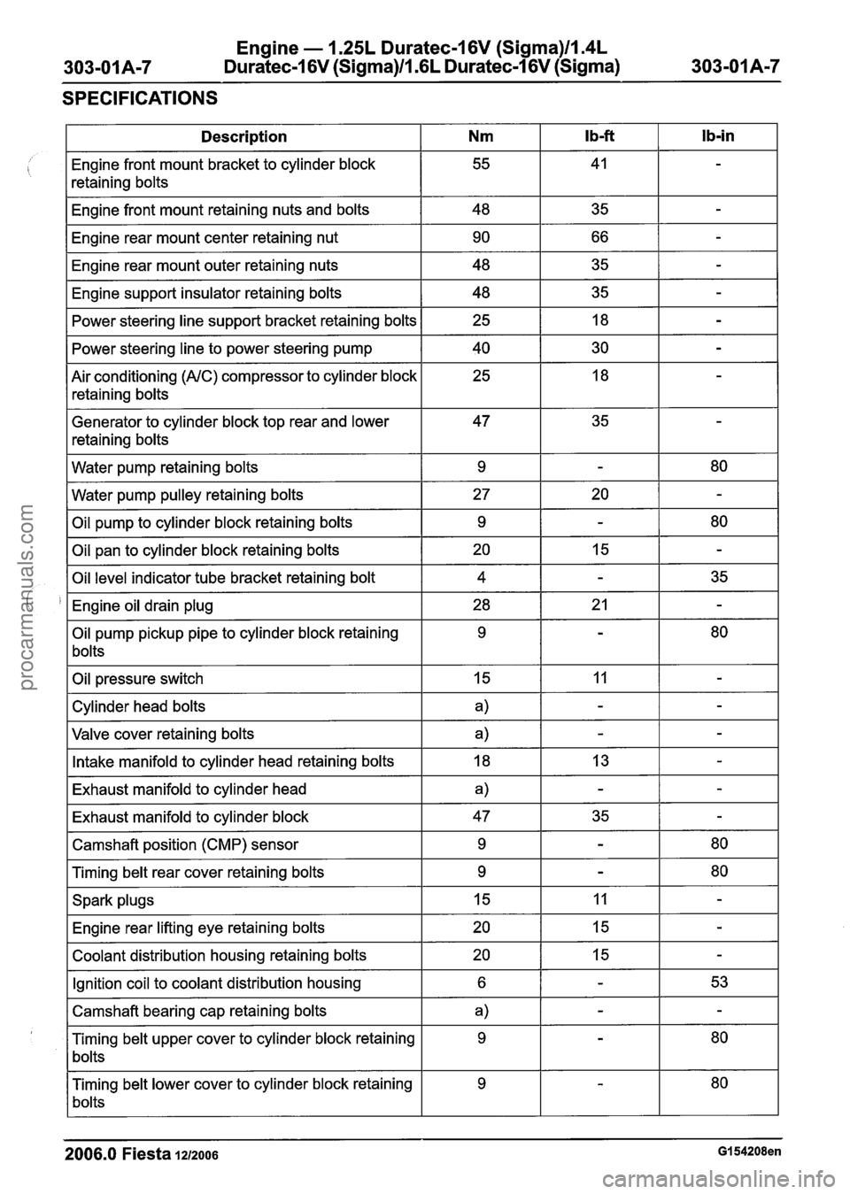
SPECIFICATIONS
2006.0 Fiesta 1212006 GI 54208en
Ib-in
-
-
-
-
-
-
-
-
-
80
-
80
-
35
-
80
-
-
-
-
-
-
80
80
-
-
-
53
-
80
80
Ib-ft
41
35
66
35 35 18
30
18
35
-
20
-
15
-
21
-
11
-
-
13
-
35
-
-
11
15
15
-
-
-
-
Description
Engine front mount bracket to cylinder block
retaining bolts
Engine front mount retaining nuts and bolts
Engine rear mount center retaining nut
Engine rear mount outer retaining nuts
Engine support insulator retaining bolts Power steering line support bracket retaining bolts
Power steering line to power steering pump
Air conditioning
(AIC) compressor to cylinder block
retaining bolts
Generator to cylinder block top rear and lower
retaining bolts
Water pump retaining bolts
Water pump pulley retaining bolts
Oil pump to cylinder block retaining bolts
Oil pan to cylinder block retaining bolts
Oil level indicator tube bracket retaining bolt
Engine oil drain plug
Oil pump pickup pipe to cylinder block retaining
bolts
Oil pressure switch
Cylinder head bolts
Valve cover retaining bolts
Intake manifold to cylinder head retaining bolts
Exhaust manifold to cylinder head
Exhaust manifold to cylinder block
Camshaft position (CMP) sensor
Timing belt rear cover retaining bolts
Spark plugs Engine rear lifting eye retaining bolts
Coolant distribution housing retaining bolts
Ignition coil to coolant distribution housing
Camshaft bearing cap retaining bolts
Timing belt upper cover to cylinder block retaining
bolts
Timing belt lower cover to cylinder block retaining
bolts
Nm
55
48 90
48
48 25
40 25
47
9
27 9
20 4
28 9
15
a)
a)
18
a)
47 9
9
15
20
20
6
a)
9
9
procarmanuals.com
Page 484 of 1226
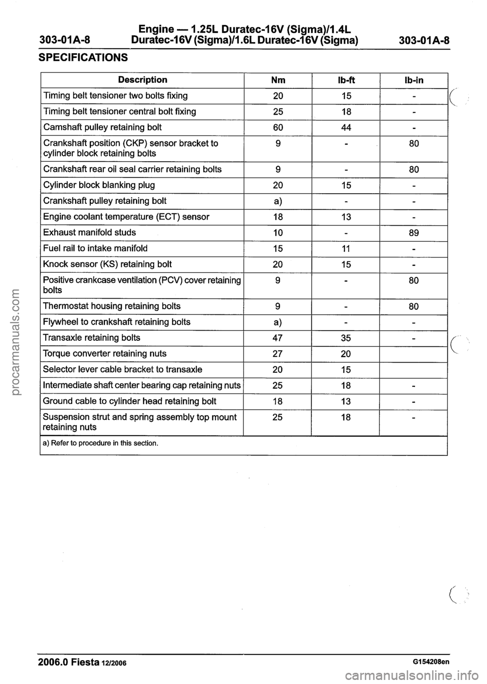
Engine - I .25L Duratec-1 6V (Sigma)llI4L
Duratec-1 6V (Sigma)ll .6L Duratec-I 6V (Sigma)
SPECIFICATIONS
1 Description I Nm I Ib-ft I Ib-in I
I Camshaft pulley retaining bolt I 60 I 44 I - I
Timing belt tensioner two bolts fixing
Timing belt tensioner central bolt fixing
Crankshaft position (CKP) sensor bracket to
cylinder block retaining bolts
I Crankshaft rear oil seal carrier retaining bolts I 9 1 - I 80 I
20
25
I Cylinder block blanking plug I 20 I 15 1 - I
I Crankshaft pulley retaining bolt I a) I - I - I
15
18
I Engine coolant temperature (ECT) sensor I 18 I 13 I - I
-
-
I Exhaust manifold studs I 10 I - I 89 I
Positive crankcase ventilation (PCV) cover retaining
1 bolts Fuel
rail to intake manifold
Knock sensor (KS) retaining bolt
I Thermostat housing retaining bolts I 9 I - 1 80 I
I Flywheel to crankshaft retaining bolts I a) I - I - I
15
20
I Selector lever cable bracket to transaxle I 20 I 15 I I
11
15
Transaxle retaining bolts
Torque converter retaining nuts
I Intermediate shaft center bearing cap retaining nuts 1 25 I 18 I - I
-
-
I Ground cable to cylinder head retaining bolt I 18 I 13 I - I
47
27
Suspension strut and spring assembly top mount
retaining nuts
I a) Refer to procedure in this section.
35
20
2006.0 Fiesta 1212006 GI 54208en
-
procarmanuals.com
Page 497 of 1226
Engine - 1.25L Duratec-I 6V (Sigma)ll14L
Duratec-1 6V (Sigma)ll16L Duratec-1 6V (Sigma)
IN-VEHICLE REPAIR
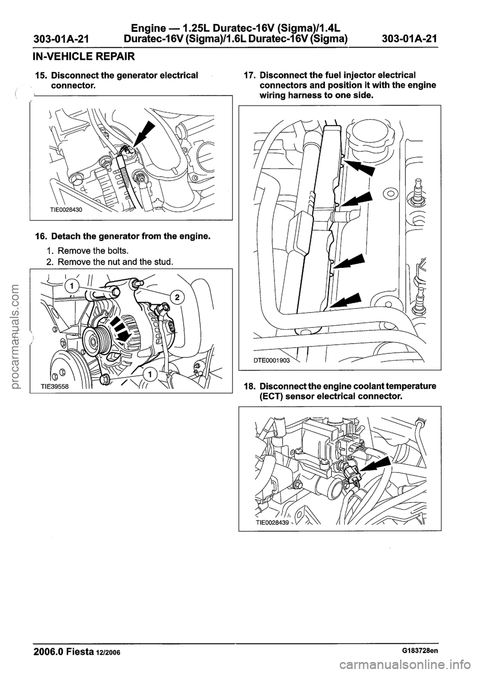
15. Disconnect the generator electrical 17. Disconnect the fuel injector electrical
connector. connectors and
position it with the engine
i wiring harness to one side.
16. Detach the generator from the engine.
1. Remove the bolts.
2. Remove the nut and the stud.
18. Disconnect the engine coolant temperature
(ECT) sensor electrical connector.
2006.0 Fiesta 1~12006 GI 83728en
procarmanuals.com
Page 498 of 1226
Engine - 1.25L Duratec-1 6V (Sigma)llI4L
Duratec-1 6V (Sigma)/l .6L Duratec-1 6V (Sigma)
IN-VEHICLE REPAIR
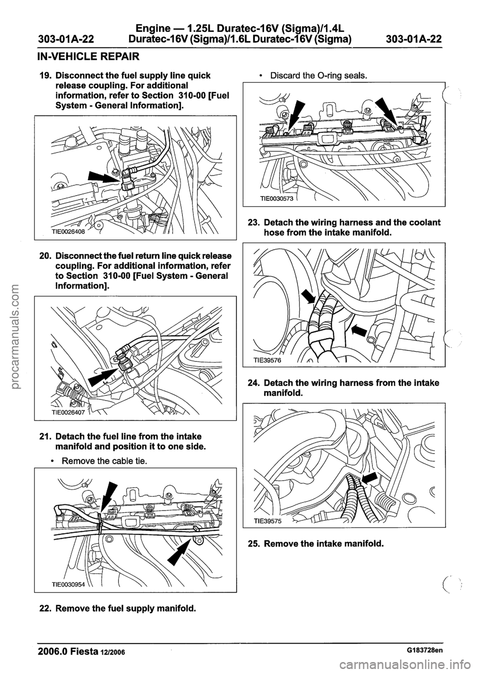
19. Disconnect the fuel supply line quick Discard the O-ring seals.
release coupling. For additional
information, refer to Section
31 0-00 [Fuel
System
- General Information].
20. Disconnect the fuel return line quick release
coupling. For additional information, refer
to Section
31 0-00 [Fuel System - General
Information].
21. Detach the fuel line from the intake
manifold and position
it to one side.
Remove the cable tie.
22.
Remove the fuel supply manifold.
23. Detach the wiring harness and the coolant
hose from the intake manifold.
24. Detach the wiring harness from the intake
manifold.
25. Remove the intake manifold.
2006.0 Fiesta 1212006 GI 83728en
procarmanuals.com
Page 499 of 1226
Engine - 1.25L Dura
303-01 A-23 Duratec-1
6V (Sigma)ll .(
:ec-I 6V (Sigma)llm4L
L
Duratec-1 6V (Sigma)
303-01 Am23
IN-VEHICLE REPAIR
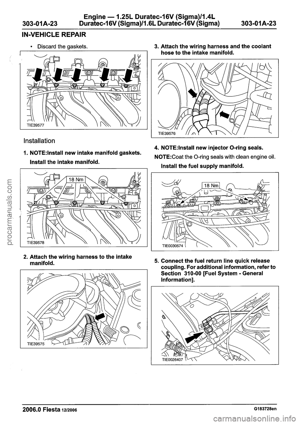
Discard the gaskets.
Installation
3. Attach the wiring harness and the coolant
hose to the intake manifold.
4. N0TE:lnstall new injector O-ring seals.
1. N0TE:lnstall new intake manifold gaskets. N0TE:Coat the 0-rina seals with clean enaine oil.
Install the intake manifold. V "
Install the fuel supply manifold.
2. Attach the wiring harness to the intake
manifold. 5. Connect the fuel return line quick release
coupling. For additional information, refer to
Section
31 0-00 [Fuel System - General
Information].
2006.0 Fiesta 1212006 GI 83728en
procarmanuals.com
Page 500 of 1226
Engine - 1.25L Duratec-1 6V (Sigma)llI4L
Duratec-1 6V (Sigma)/l .6L Duratec-1 6V (Sigma)
IN-VEHICLE REPAIR
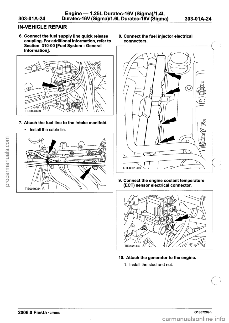
6. Connect the fuel supply line quick release
coupling. For additional information, refer to
Section 310-00 [Fuel System
- General
Information].
7. Attach the fuel line to the intake manifold.
Install the cable tie. 8.
Connect the fuel injector electrical
connectors.
9. Connect the engine coolant temperature
(ECT) sensor electrical connector.
10. Attach the generator to the engine.
1. Install the stud and nut.
2006.0 Fiesta 1212006 GI 83728en
procarmanuals.com
Page 513 of 1226
Engine - 1.25L Duratec-1 6V (Sigma)lIl4L
303-01 A-37 Duratec-1 6V (Sigma)ll.GL Duratec-1 6V (Sigma) 303-01A-37
IN-VEHICLE REPAIR
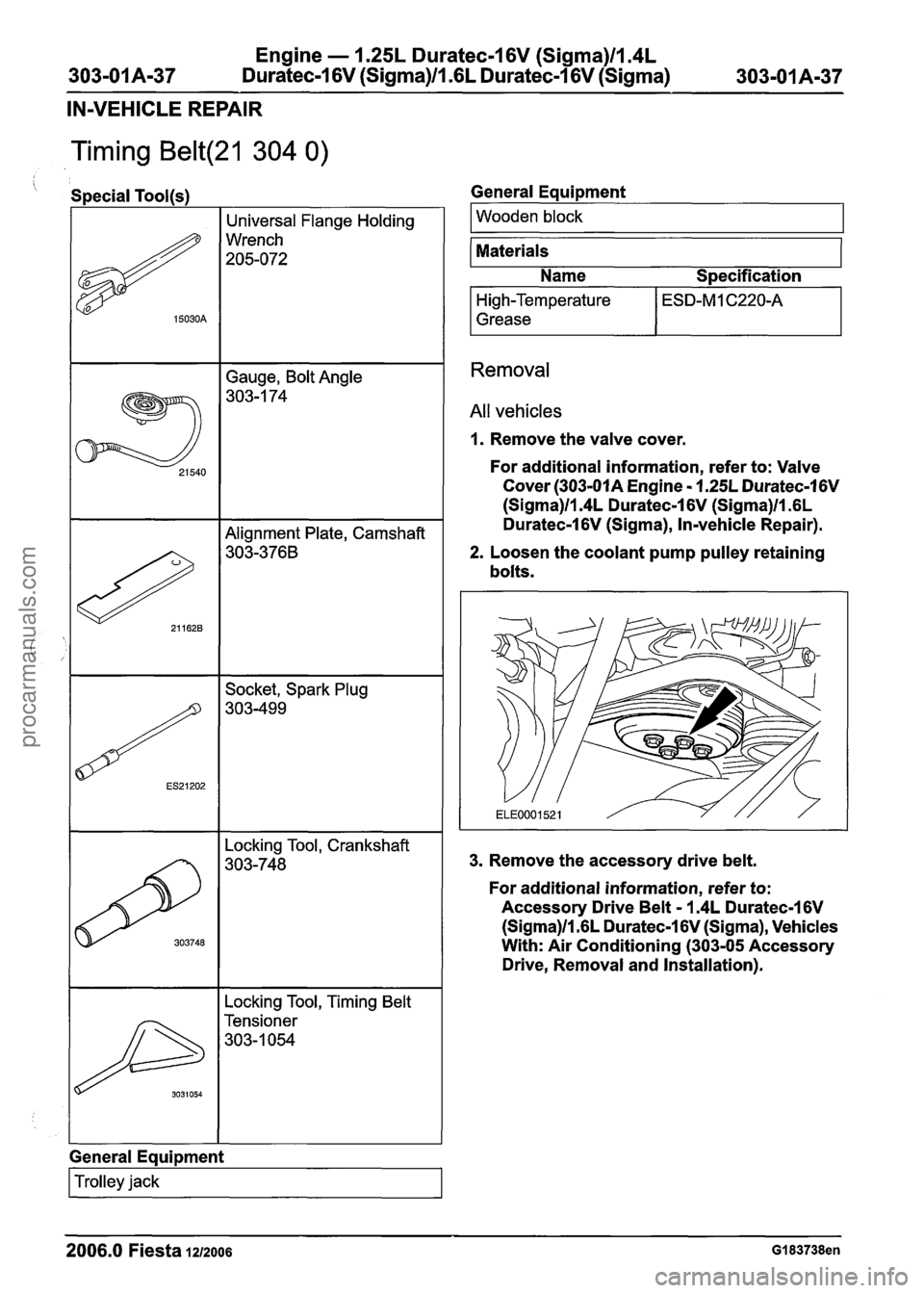
Timing Belt(21 304 0)
Gauge, Bolt Angle
303-1 74
' Special Tool(s)
# 15030A
Locking Tool, Timing Belt
I Tensioner
303-1054
Universal Flange Holding
Wrench
205-072
303748
General Equipment
Locking Tool, Crankshaft
303-748
I Trolley jack I
General Eaui~ment
I Wooden block I - --
Materials
Name
S~ecification
High-Temperature
Grease
Removal
All vehicles
1. Remove the valve cover.
For additional information, refer to: Valve
Cover
(303-01A Engine - 1.25L Duratec-1 6V
(Sigma)ll.4L Duratec-1 6V (Sigma)ll .6L
Duratec-1
6V (Sigma), In-vehicle Repair).
2. Loosen the coolant pump pulley retaining
bolts.
3. Remove the accessory drive belt.
For additional information, refer to:
Accessory Drive Belt
- 1.4L Duratec-I 6V
(Sigma)/l.GL Duratec-1 6V (Sigma), Vehicles
With: Air Conditioning (303-05 Accessory
Drive, Removal and Installation).
2006.0 Fiesta 1212006 GI 83738en
procarmanuals.com