lock FORD FIESTA 2007 Workshop Manual
[x] Cancel search | Manufacturer: FORD, Model Year: 2007, Model line: FIESTA, Model: FORD FIESTA 2007Pages: 1226, PDF Size: 61.26 MB
Page 407 of 1226
211 -03-9 Steering Linkage 21 1-03-9
REMOVAL AND INSTALLATION
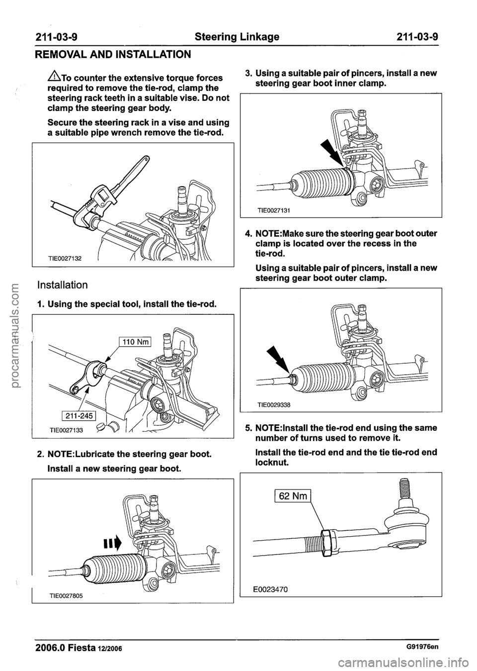
ATO counter the extensive torque forces 3. Using a suitable pair of pincers, install a new
required to remove the tie-rod, clamp the steering
gear boot inner clamp.
steering rack teeth in a suitable vise. Do not
clamp the steering gear body.
Secure the steering rack in a vise and using
a suitable pipe wrench remove the tie-rod.
Installation
1. Using the special tool, install the tie-rod.
4. N0TE:Make sure the steering gear boot outer
clamp is located over the recess in the
tie-rod.
Using a suitable pair of pincers, install a new
steering gear boot outer clamp.
5. N0TE:lnstall the tie-rod end using the same
number of turns used to remove
it.
2. N0TE:Lubricate the steering gear boot. Install the tie-rod end and the
tie tie-rod end
locknut.
Install a new steering gear boot.
2006.0 Fiesta 1212006 G91976en
procarmanuals.com
Page 412 of 1226
2 1 1 -04-4 Steering Column 21 1 -04-4
REMOVAL AND INSTALLATION
Steering Wheel(l3 524 0)
Removal
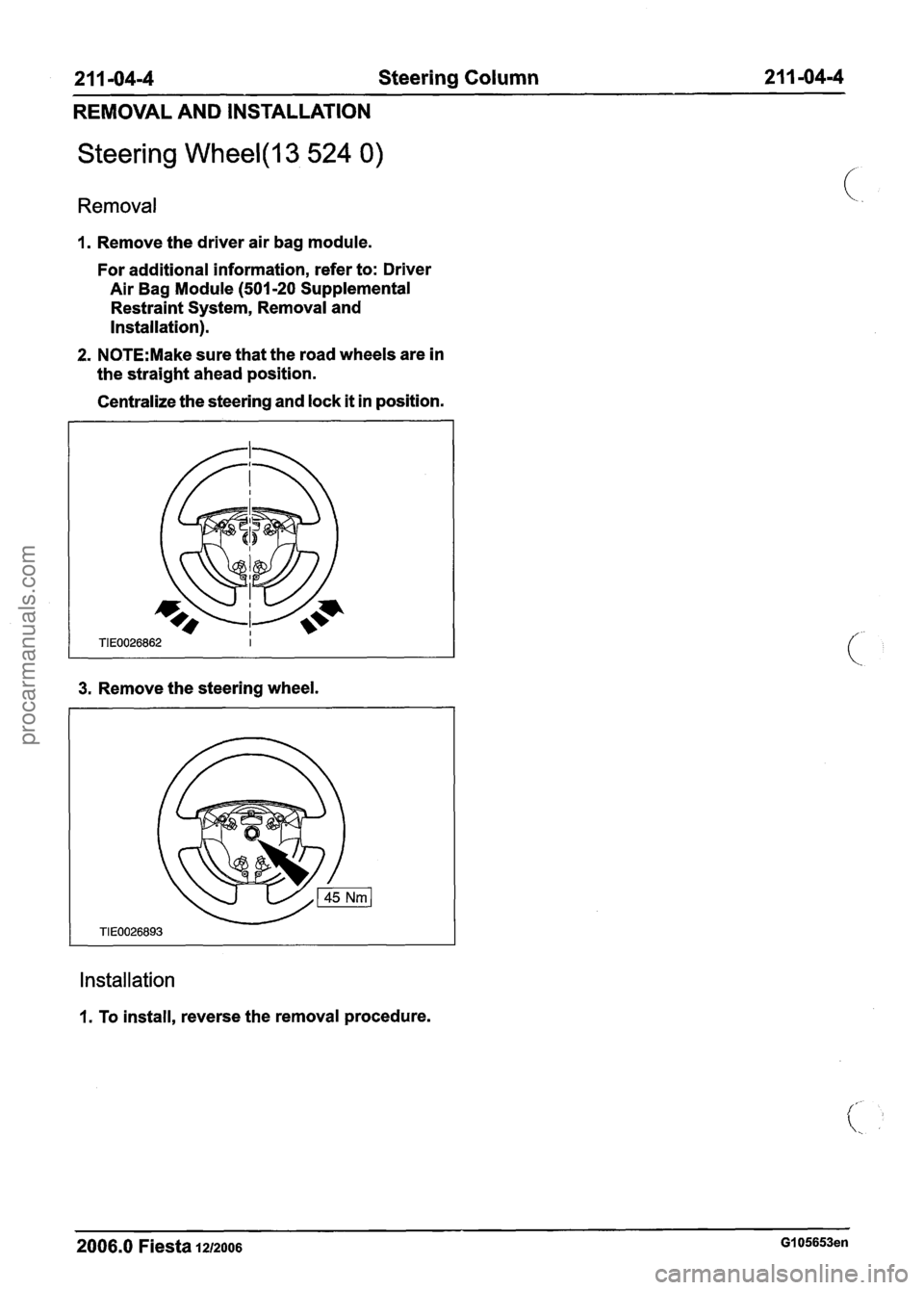
I. Remove the driver air bag module.
For additional information, refer to: Driver
Air Bag Module
(501-20 Supplemental
Restraint System, Removal and
Installation).
2. N0TE:Make sure that the road wheels are in
the straight ahead position.
Centralize the steering and lock
it in position.
3. Remove the steering wheel.
Installation
1. To install, reverse the removal procedure.
2006.0 Fiesta 1212006 GI 05653en
procarmanuals.com
Page 413 of 1226
21 1 -04-5 Steering Column 2 I I -04-5
REMOVAL AND INSTALLATION
Steering Column(l3 542 0)
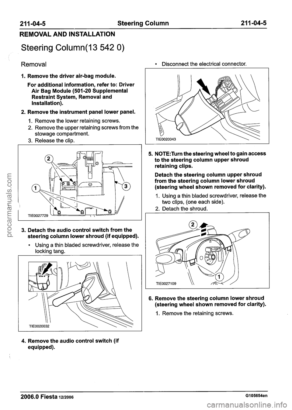
Removal Disconnect the electrical connector.
1. Remove the driver air-bag module.
For additional information, refer to: Driver
Air Bag Module (501-20 Supplemental
Restraint System, Removal and
Installation).
2. Remove the instrument panel lower panel.
1. Remove the lower retaining screws.
2. Remove the upper retaining screws from the
stowage compartment.
3. Release the clip.
3. Detach the audio control switch from the
steering column lower shroud (if equipped).
Using a thin bladed screwdriver, release the
locking tang.
4. Remove the audio control switch (if
equipped).
5. N0TE:Turn the steering wheel to gain access
to the steering column upper shroud
retaining clips.
Detach the steering column upper shroud
from the steering column lower shroud (steering wheel shown removed for clarity).
1 . Using a thin bladed screwdriver, release the
two clips, (one each side).
2. Detach the shroud.
6. Remove the steering column lower shroud
(steering wheel shown removed for clarity).
1. Remove the retaining screws.
2006.0 Fiesta 1212006 GI 05654en
procarmanuals.com
Page 414 of 1226
2 1 1 -04-6 Steering Column 21 1 -04-6
REMOVAL AND INSTALLATION
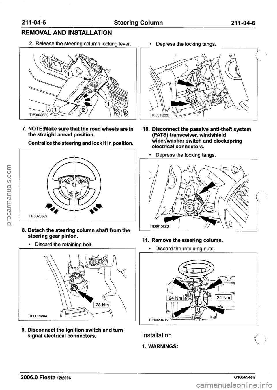
2. Release the steering column locking lever. Depress the locking tangs.
1--
7. N0TE:Make sure that the road wheels are in 10. Disconnect the passive anti-theft system
the straight ahead position.
(PATS) transceiver, windshield
Centralize the steering and lock it in position. wiperlwasher
switch and clockspring
electrical connectors.
Depress the locking tangs.
8. Detach the steering column shaft from the
steering gear pinion.
Discard the retaining bolt. 11. Remove the steering column.
Discard the retaining nuts.
9. Disconnect the ignition switch and turn
signal electrical connectors.
Installation
1. WARNINGS:
2006.0 Fiesta 1212006 GI 05654en
procarmanuals.com
Page 415 of 1226
2 1 1 -04-7 Steering Column 21 I -04-7
REMOVAL AND INSTALLATION
Anstall a new steering column shaft to
steering gear pinion retaining bolt. Failure
, to follow this instruction may result in
personal injury.
A~ake sure that the steering column
locking lever is in the locked position. Failure
to follow this instruction may result in
personal injury.
Anstall new steering column retaining
nuts. Failure to follow this instruction may
result in personal injury.
To install, reverse the removal procedure.
2006.0 Fiesta 1212006 GI 05654en
procarmanuals.com
Page 416 of 1226
2 1 1 -04-8 Steering Column 2 1 1 -04-8
DISASSEMBLY AND ASSEMBLY
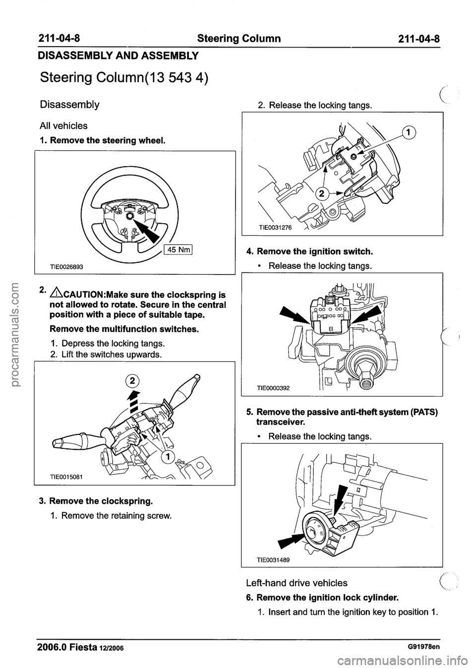
Steering Column(l3 543 4)
Disassembly 2. Release the locking tangs. (:
All vehicles
1. Remove the steering wheel.
4. Remove the ignition switch.
Release the locking tangs.
3. Remove the clockspring.
1. Remove the retaining screw.
*' ACAUTION:M~~~ sure the clockspring is
not allowed to rotate. Secure in the central
position with a piece of suitable tape.
Remove the multifunction switches.
1. Depress the locking tangs.
2. Lift the switches upwards.
5. Remove the passive anti-theft system (PATS)
transceiver.
1
TIE0000392
Release the locking tangs.
Left-hand drive vehicles
6. Remove the ignition lock cylinder.
1. Insert and turn the ignition key to position 1.
2006.0 Fiesta 12/2006 G91978en
procarmanuals.com
Page 417 of 1226
21 I -04-9 Steering Column 2 1 1 -04-9
DISASSEMBLY AND ASSEMBLY
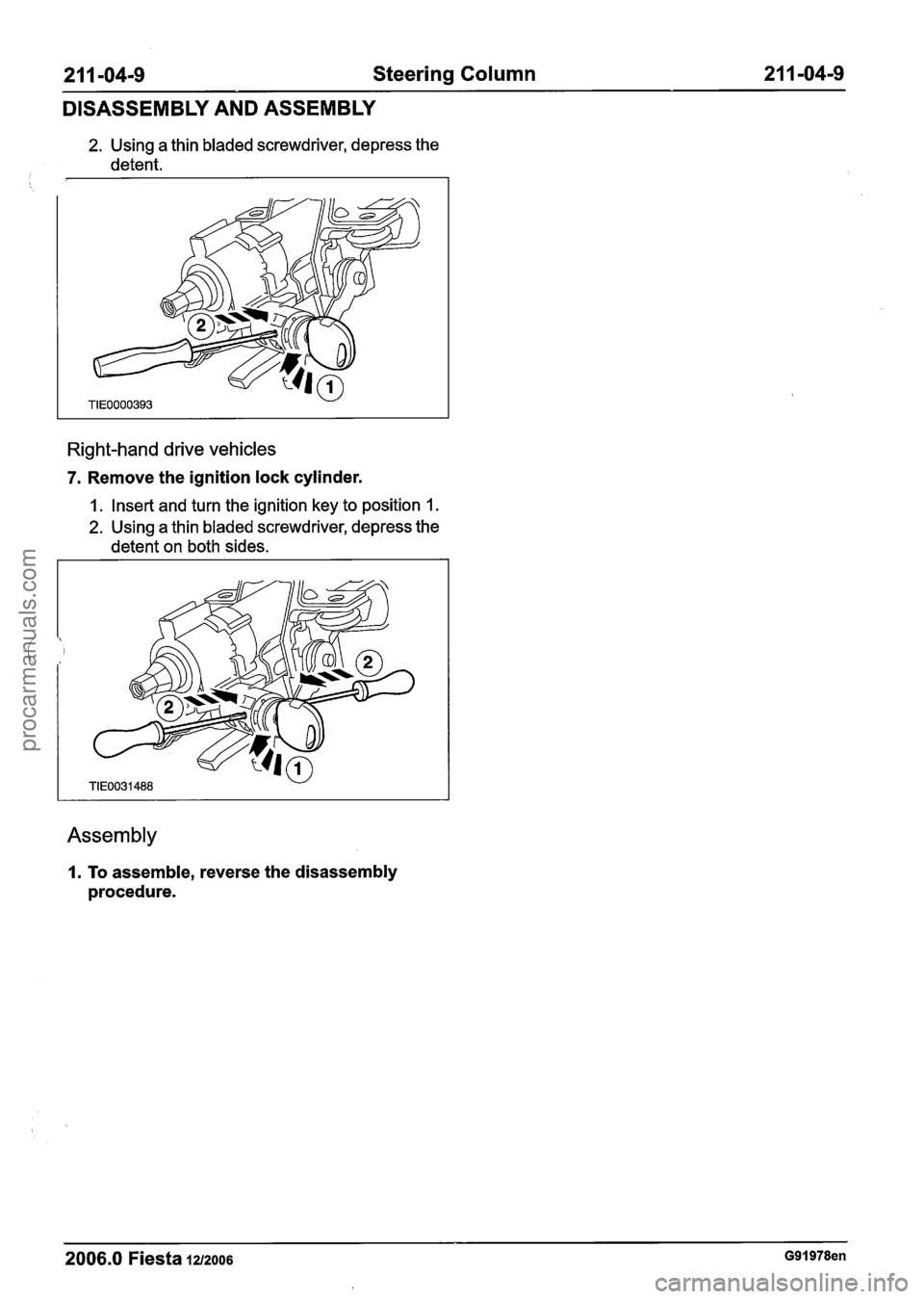
2. Using a thin bladed screwdriver, depress the
detent.
Right-hand drive vehicles
7. Remove the ignition lock cylinder.
1. Insert and turn the ignition key to position 1.
2. Using a thin bladed screwdriver, depress the
detent on both sides.
Assembly
1. To assemble, reverse the disassembly
procedure.
2006.0 Fiesta 1212006 G91978en
procarmanuals.com
Page 420 of 1226

21 1-05-2 Steering Column Switches 21 1-05-2
REMOVAL AND INSTALLATION
Ignition Switch(36 424 0)
Removal 2. Detach the shroud.
I. Disconnect the battery ground cable. For
additional information, refer to
Section
414-01 [Battery, Mounting and
Cables].
2. Detach the audio control switch from the
steering column lower shroud (if equipped).
Using a thin bladed screwdriver, release the
locking tang.
3. Remove the audio control switch (if
equipped).
Disconnect the electrical connector.
.. N0TE:Turn the steering wheel to access the
steering column upper shroud retaining
clips.
Detach the steering column upper shroud
from the steering column lower shroud (steering wheel shown removed for clarity).
5. Remove the steering column lower shroud
(steering wheel shown removed for clarity).
1. Release the steering column locking lever.
2. Remove the retaining screws.
6. Disconnect the ignition switch electrical
connector.
1. Using a thin bladed screwdriver, release the 7m Remove the ignition two clips (one each side).
2006.0 Fiesta 1212006 GI 05656en
procarmanuals.com
Page 421 of 1226
21 1-05-3 Steering Column Switches 21 1 -05-3
REMOVAL AND INSTALLATION
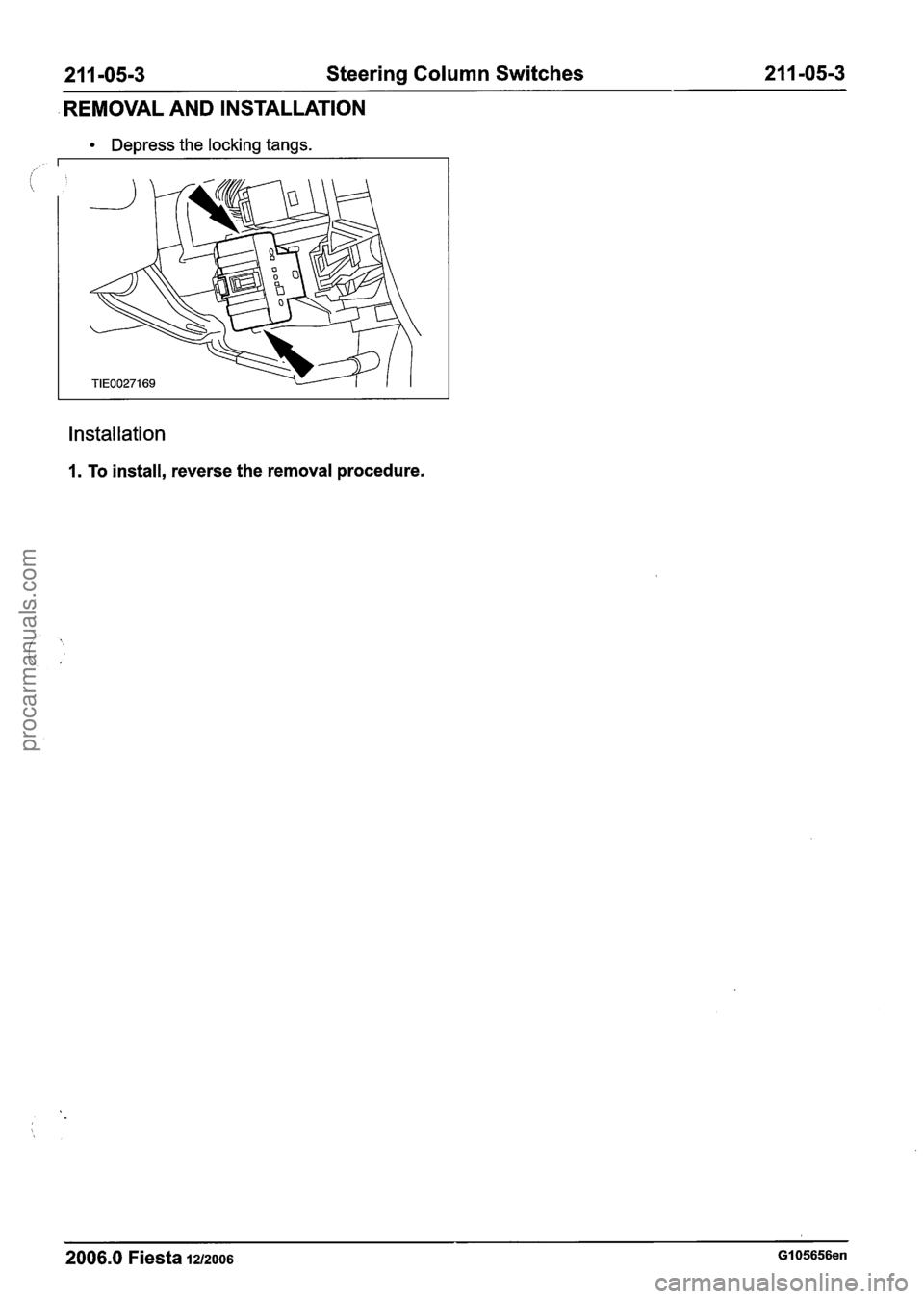
Depress the locking tangs.
Installation
1. To install, reverse the removal procedure.
2006.0 Fiesta 1212006 GI 05656en
procarmanuals.com
Page 423 of 1226
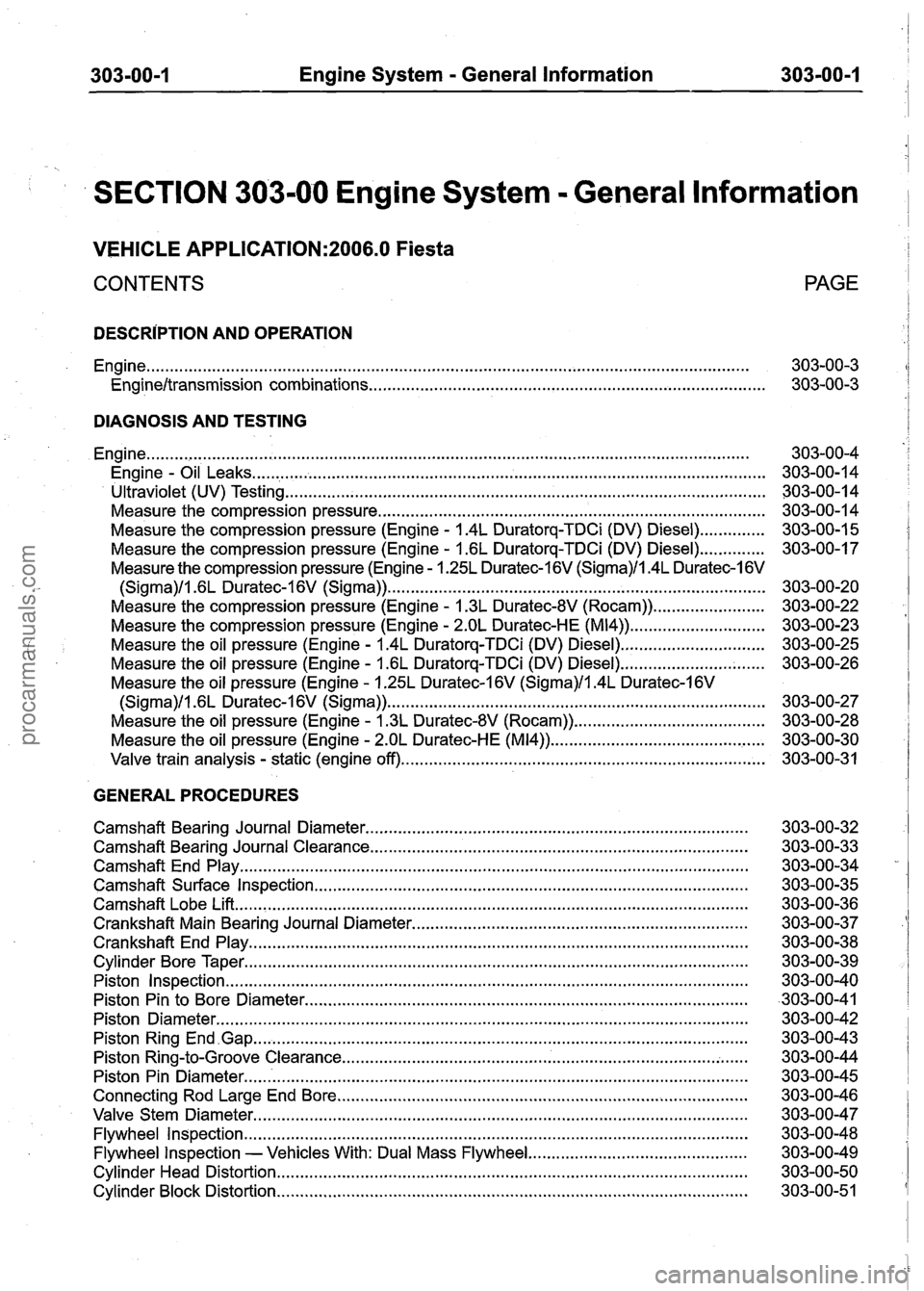
303-00-1 Engine System = General Information 303-00-1
SECTION 303-00 Engine System . General lnformation
VEHICLE APPLICATION:2006.0 Fiesta
CONTENTS PAGE
DESCRIPTION AND
OPERATION
Engine
........................................................................\
......................................................... 303-00-3
Engineltransmission combinations ........................................................................\
........ 303-00-3
DIAGNOSIS AND TESTING
........................................................................\
.......................................................... Engine
. Engine Oil Leaks ........................................................................\
........................................
Ultraviolet (UV) Testing ........................................................................\
...............................
Measure the compression pressure ........................................................................\
...........
.............. Measure the compression pressure (Engine . 1.4L Duratorq-TDCi (DV) Diesel)
Measure the compression pressure (Engine
. 1.6L Duratorq-TDCi (DV) Diesel) ..............
Measure the compression pressure (Engine . 1.25L Duratec-I 6V (Sigma)/l.4L Duratec-I 6V
........................................................................\
......... (Sigma)ll . 6L Duratec-I 6V (Sigma))
Measure the compression pressure (Engine
. 1.3L Duratec-8V (Rocam)) ........................
Measure the compression pressure (Engine . 2.OL Duratec-HE (M14)) .............................
. Measure the oil pressure (Engine 1.4L Duratorq-TDCi (DV) Diesel) ...............................
Measure the oil pressure (Engine . 1.6L Duratorq-TDCi (DV) Diesel) ...............................
Measure the oil pressure (Engine . 1.25L Duratec-1 6V (Sigma)/l.4L Duratec-1 6V
........................................................................\
......... (Sigma)/l . 6L Duratec-1 6V (Sigma))
. Measure the oil pressure (Engine 1.3L Duratec-8V (Rocam)) .........................................
. Measure the oil pressure (Engine 2.OL Duratec-HE (M14)) ...............................................
Valve train analysis . static (engine off) ........................................................................\
......
GENERAL PROCEDURES
Camshaft Bearing Journal Diameter
........................................................................\
..........
Camshaft Bearing Journal Clearance ........................................................................\
.........
Camshaft End Play ........................................................................\
.....................................
Camshaft Surface Inspection ........................................................................\
.....................
........................................................................\
...................................... Camshaft Lobe Lift
Crankshaft Main Bearing Journal Diameter
........................................................................\
Crankshaft End Play ........................................................................\
...................................
Cylinder Bore Taper ........................................................................\
....................................
Piston Inspection ........................................................................\
........................................
Piston Pin to Bore Diameter ........................................................................\
.......................
Piston Diameter ........................................................................\
..........................................
Piston Ring End .Gap ........................................................................\
...................................
............................................ ................................... Piston Ring-to-Groove Clearance ......
Piston Pin Diameter ........................................................................\
.....................................
Connecting Rod Large End Bore ........................................................................\
................
Valve Stem Diameter ........................................................................\
..................................
Flywheel Inspection ........................................................................\
....................................
............................................... Flywheel Inspection - Vehicles With: Dual Mass Flywheel
Cylinder Head Distortion ........................................................................\
.............................
Cylinder Block Distortion ........................................................................\
.............................
procarmanuals.com