automatic transmission fluid FORD FIESTA 2007 User Guide
[x] Cancel search | Manufacturer: FORD, Model Year: 2007, Model line: FIESTA, Model: FORD FIESTA 2007Pages: 1226, PDF Size: 61.26 MB
Page 621 of 1226
Engine - 1.25L Duratec-1 6V (Sigma)ll.4L
303-01 A-1 45 Duratec-1 6V (Sigma)ll .6L
Duratec-1 6V (Sigma) 303-01 A-1 45
INSTALLATION
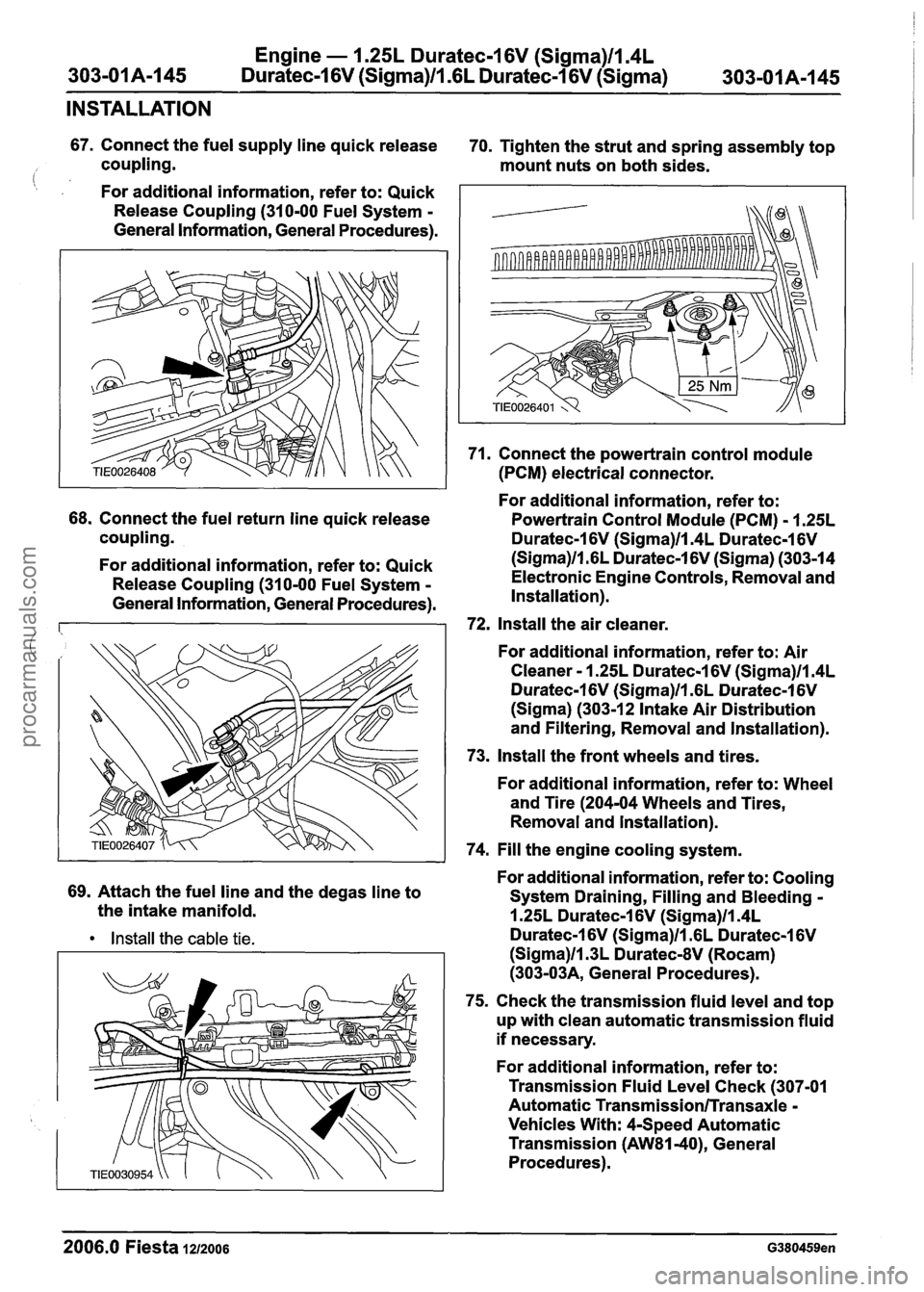
67. Connect the fuel supply line quick release
70. Tighten the strut and spring assembly top
coupling. mount nuts on both sides.
(: , For additional information, refer to: Quick
Release Coupling (310-00 Fuel System
-
General Information, General Procedures).
68. Connect the fuel return line quick release
coupling.
For additional information, refer to: Quick
Release Coupling (310-00 Fuel System
-
General Information, General Procedures).
69. Attach the fuel line and the degas line to
the intake manifold.
Install the cable tie.
71. Connect the powertrain control module
(PCM) electrical connector.
For additional information, refer to:
Powertrain Control Module (PCM)
- 1.25L
Duratec-1 6V (Sigma)llm4L Duratec-1 6V
(Sigma)ll.GL Duratec-1 6V (Sigma) (303-14
Electronic Engine Controls, Removal and
Installation).
72, Install the air cleaner.
For additional information, refer to: Air
Cleaner
- 1.25L Duratec-1 6V (Sigma)ll.4L
Duratec-1 6V (Sigma)ll.GL Duratec-1 6V
(Sigma) (303-1 2 Intake Air Distribution
and Filtering, Removal and Installation).
73. Install the front wheels and tires.
For additional information, refer to: Wheel
and Tire (204-04 Wheels and Tires,
Removal and lnstallation).
74. Fill the engine cooling system.
For additional information, refer to: Cooling
System Draining, Filling and Bleeding
-
1.25L Duratec-1 6V (Sigma)ll.4L
Duratec-1 6V (Sigma)ll .6L Duratec-1 6V
(Sigma)ll.3L DuratecdV (Rocam)
(303-03A, General Procedures).
75. Check the transmission fluid level and top
up with clean automatic transmission fluid
if necessary.
For additional information, refer to:
Transmission Fluid Level Check (307-01
Automatic
Transmission/Transaxle -
Vehicles With: 4-Speed Automatic
Transmission
(AW81-40), General
Procedures).
--
2006.0 Fiesta 1212006 G380459en
procarmanuals.com
Page 961 of 1226
Automatic Transmission/Transaxle .
Vehicles With: 4-Speed Automatic
Transmission
(AW81-40)
SECTION 307-01 Automatic Transmission/Transaxle
. Vehicles With: 4-Speed Automatic Transmission
(AW81-40)
VEHICLE APPLICATION:2006.0 Fiesta
CONTENTS PAGE
SPECIFICATIONS
Specifications
........................................................................\
.............................................. 307-0 1 -3
DESCRIPTION AND OPERATION
Automatic Transaxle
........................................................................\
...................................
Transmission cross-section ........................................................................\
........................
Torque converter with Torque Converter Clutch (TCC) ......................................................
Fluid pump and stator shaft ........................................................................\
........................
........................................................................\
......... Planetary gearset ......................... .:
Clutches and brakes ........................................................................\
...................................
Intermediate gear stage and differential assembly .............................................................
Main control body ........................................................................\
.......................................
Internal' gearshift mechanism ........................................................................\
.....................
Fluid circuit ........................................................................\
.................................................
........................................................................\
....................................... Identification Tags
Type plate
........................................................................\
...................................................
Transmission Ranges and Power Flow ........................................................................\
......
Transmission ratio and power flow route - 1st gear ............................................................
Transmission ratio and power flow route - 2nd gear ..........................................................
Transmission ratio and power flow route . 3rd gear ...........................................................
Transmission ratio and power flow route . 4th gear ...........................................................
Transmission ratio and power flow route . reverse gear ....................................................
Transaxle Electronic Control System ........................................................................\
..........
........................................................................\
..................................................... Overview
Transmission control unit
........................................................................\
............................
........................................................................\
.................................... Gearshift strategies
Selector lever positions
........................................................................\
..............................
Signal transmission on the CAN databus ........................................................................\
...
........................................................................\
...................................................... Sensors
........................................................................\
.................................................... Actuators
DIAGNOSIS AND TESTING
Automatic Transaxle
........................................................................\
................................... 307-01
Inspection and Verification ........................................................................\
.................... 307-01
Diagnostic Trouble Code Chart
........................................................................\
.................. 307-01
........................................................................\
...................................... Line Pressure Test 307-01
Stall Speed Test
........................................................................\
....................................... 307-01
Time Lag Test
........................................................................\
............................................. 307-01
procarmanuals.com
Page 962 of 1226
Automatic Transmission/Transaxle -
Vehicles With: 4-Speed Automatic
Transmission
(AW81-40)
GENERAL PROCEDURES /' -
.. Transmission Fluid Level Check.. ........................................................................\
............... 307-01 - k
........................................................................\
............ Transmission Fluid Drain and Refill 307-01 -53
IN-VEHICLE REPAIR
........................................................................\
.............. Transmission Range (TR) Sensor 307-01 -55
Halfshaft Seal LH.. ........................................................................\
...................................... 307-01 -58
Halfshaft Seal RH ........................................................................\
....................................... 307-01 -59
Turbine Shaft Speed (TSS) Sensor ........................................................................\
......... 307-01-60
Vehicle Speed Sensor (VSS).. ........................................................................\
................ 307-01 -61
REMOVAL AND INSTALLATION
Transaxle.. ........................................................................\
.................................................. 307-01 -62
procarmanuals.com
Page 963 of 1226
Automatic TransmissionlTransaxle -
Vehicles With: 4-Speed Automatic
Transmission
(AW81-40)
SPECIFICATIONS
Lubricants, Fluids, Sealers and Adhesives
A WARN1NG:Refer to the Material Safety
Data Sheets for the Automatic Transmis-
sion Fluid E-AW. Failure to follow this
instruction may result in personal injury.
Certain Transmission and Power Steering
fluids supplied to Ford contain additives
which may cause skin irritation or other
skin reactions after contact.
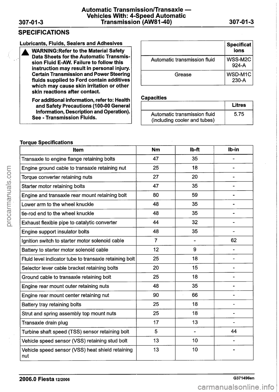
Automatic transmission fluid
Grease
Capacities
Specif icat
ions
WSS-M2C 924-A
WSD-MI C
230-A
For additional information, refer to: Health
and Safety Precautions
(1 00-00 General
Information, Description and Operation).
See
- Transmission Fluids. Automatic transmission fluid
(including cooler and tubes)
I Transaxle to engine flange retaining bolts I 47 I 35 I - I
Litres
5.75
Torque Specifications
I Engine ground cable to transaxle retaining nut I 25 I 18 I - I
I Torque converter retaining nuts I 27 I 20 I - I
lb-in Item
I Starter motor retaining bolts I 47 I 35 I - I
,I Engine and transaxle rear mount retaining bolt I 80 I 59 I - I
Nm
I Lower arm to the wheel knuckle I 48 I 35 I - I
I b-ft
I tie-rod end to the wheel knuckle I 48 I 35 I - I
I Exhaust flexible pipe to catalytic converter I 44 I 32 I - I
I Engine support insulator bolts I 48 I 35 I - I
IGnition switch to starter motor solenoid cable I 7 I - I 62 I
I Battery to starter motor solenoid cable I 12 I 9 I - I
-I indicator tube to transaxle retaining bolt I 25 I 18 I - I
I Selector lever cable bracket retaining bolts I 20 I 15 I - I - -
I Ground cable to transaxle retaining bolt
I Engine rear mount outer retaining nuts
I Engine rear mount center retaining nut I 90 I 66 I - I
I Battery tray retaining bolts I 25 I 18 I - I
I Strut and spring assembly top mount nuts I 25 I 18 I - I - -
Transaxle drain plug
Vehicle speed sensor (VSS) heat shield retaining
1 nut
Turbine
shaft speed (TSS) sensor retaining bolt
Vehicle speed sensor (VSS) retaining stud bolt
2006.0 Fiesta 1212006 G371496en
17
5
13 13 -
-
10
44
-
procarmanuals.com
Page 966 of 1226
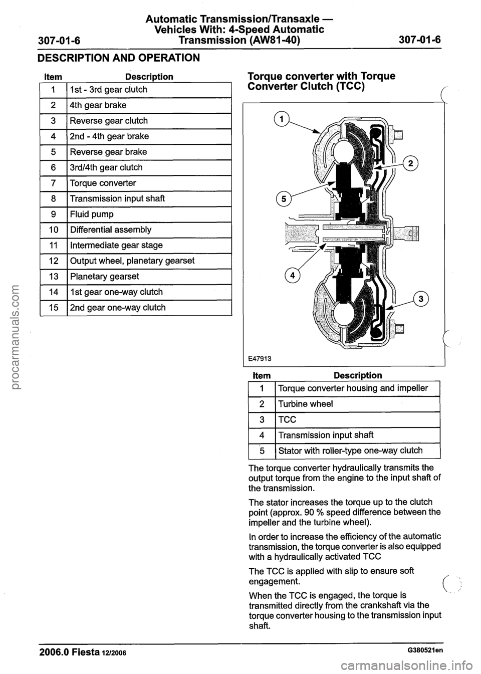
Automatic Tr;
Vehicles Wil
307-01 -6 Transn
~nsmission/Transaxle -
:h: 4-Speed Automatic
~ission (AW81-40) --
DESCRIPTION AND OPERATION
Item Description
I 1 I I st - 3rd gear clutch 1
1 2 14th gear brake I
1 3 1 Reverse gear clutch I
1 4 )2nd - 4th gear brake I
1 5 1 Reverse gear brake I
1 6 1 3rdl4th gear clutch I
1 7 ITorque converter 1
1 8 1 Transmission input shaft I
1 9 I Fluid pump I - --
[ 10 1 Differential assembly I
~l~put wheel, planetary gearset I
11
1 13 1 Planetary gearset I
Intermediate gear stage
vlIlstgear one-way clutch I
1 15 1 2nd gear one-way clutch I
Torque converter with Torque
Converter Clutch (TCC)
Item Description
I 1 I Torque converter housing and impeller I
1 2 1 Turbine wheel 1
1 4 1 Transmission input shaft I
FlGwith roller-type one-way clutch (
The torque converter hydraulically transmits the
output torque from the engine to the input shaft of
the transmission.
The stator increases the torque up to the clutch
point (approx. 90
% speed difference between the
impeller and the turbine wheel).
In order to increase the efficiency of the automatic
transmission, the torque converter is also equipped
with a hydraulically activated TCC
The TCC is applied with slip to ensure soft
engagement.
i
When the TCC is engaged, the torque is '..
transmitted directly from the crankshaft via the
torque converter housing to the transmission input
shaft.
2006.0 Fiesta 1212006 ~380521 en
procarmanuals.com
Page 967 of 1226
Automatic Transmission/Transaxle -
Vehicles With: 4-Speed Automatic
Transmission (AW81-40)
DESCRIPTION AND OPERATION
The TCC is engaged depending on the current
driving situation when the selector lever is in
I position "D" and 3rd or 4th gear is engaged. When
4th gear is disabled
(OID Off) the TCC is
engaged in 3rd gear depending on the current
driving situation.
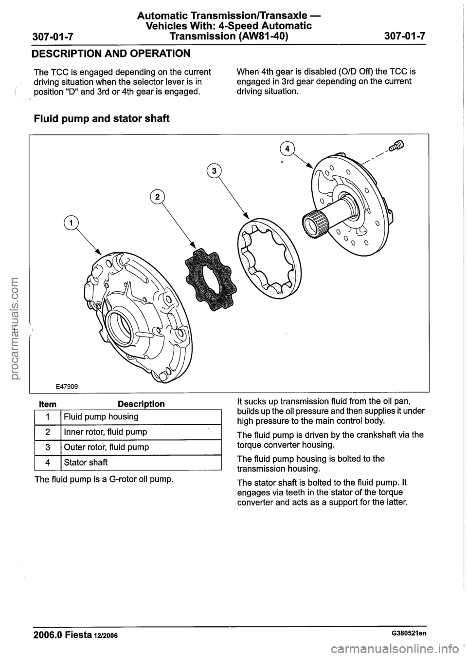
Fluid pump and stator shaft
Item Description It sucks up transmission fluid from the oil pan,
1
2
3
2006.0 Fiesta 1212006 G380521 en
Fluid pump housing
4 builds
up the oil pressure and then supplies it under
high pressure to the main control body.
Inner rotor, fluid pump
Outer rotor, fluid pump The
fluid pump is driven by the crankshaft via the
torque converter housing.
transmission housing.
The fluid pump is a G-rotor oil pump.
The stator shaft is bolted to the fluid pump. It
engages via teeth in the stator of the torque
converter and acts as a support for the latter.
Stator
shaft The
fluid pump housing is bolted to the
procarmanuals.com
Page 974 of 1226
Automatic Transmission/Transaxle -
Vehicles With: 4-Speed Automatic
Transmission
(AW81-40)
DESCRIPTION AND OPERATION
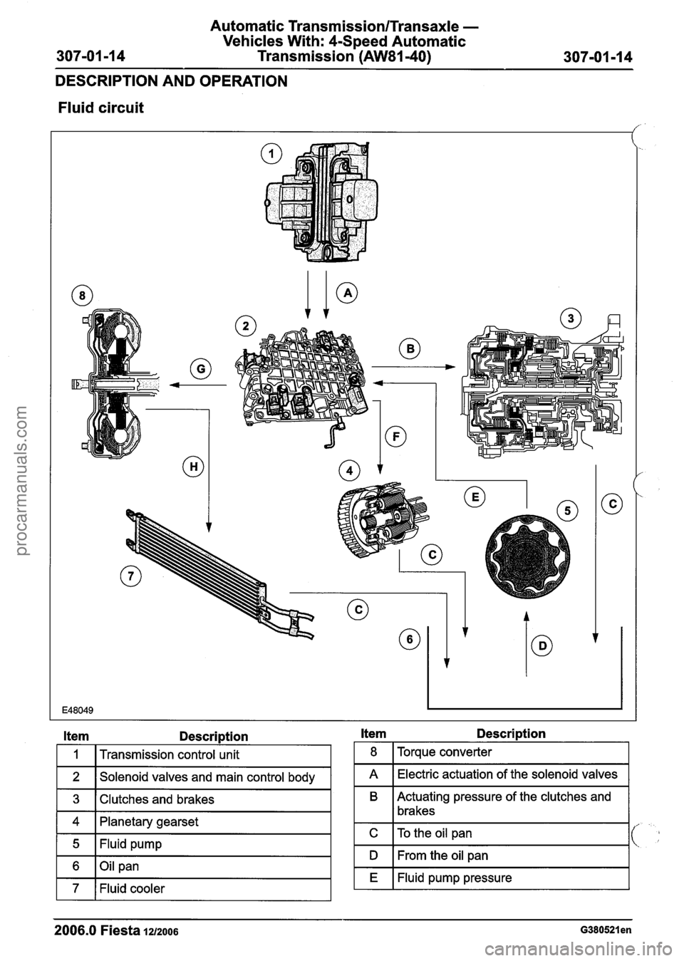
Fluid circuit
Item Description
I 1 I Transmission control unit
1 2 1 Solenoid valves and main control body I
1 3 I Clutches and brakes I
1 4 1 Planetary gearset
1 5 1 Fluid pump I
1 6 1Oil pan I
1 7 1 Fluid cooler I
Item Description
1 8 I Torque converter I
I A I Electric actuation of the solenoid valves I
B Actuating pressure of the clutches and
1 lbrakes
I C ITo the oil pan I
I D I From the oil pan I
I E I Fluid pump pressure I
2006.0 Fiesta 121~006 ~380521 en
procarmanuals.com
Page 975 of 1226
Automatic Transmission/Transaxle -
Vehicles With: 4-Speed Automatic
Transmission
(AW81-40)
DESCRIPTION AND OPERATION
Item Description
I H I To the fluid cooler I
, i
2006.0 Fiesta 1212006 G380521 en
F
G
Lubrication
To the torque converter
procarmanuals.com
Page 989 of 1226
Automatic Transmission/Transaxle -
Vehicles With: 4-Speed Automatic
Transmission (AW81-40)
DESCRIPTION AND OPERATION
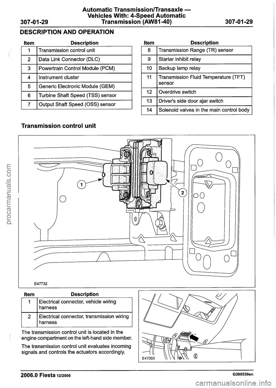
Item Description
1 5 1 Generic Electronic Module (GEM) I
I
1 6 1 Turbine Shaft Speed (TSS) sensor I
1 7 1 Output Shaft Speed (OSS) sensor I
1
2
3
4
l tem Description
Transmission control unit
Data Link Connector (DLC)
Powertrain Control Module (PCM)
Instrument cluster
1 8 I Transmission Range (TR) sensor I
1 9 1 Starter inhibit relay I
1 10 1 Backup lamp relay I
11 Transmission Fluid Temperature (TFT)
I I sensor
1 12 loverdrive switch I
1 13 1 Driver's side door ajar switch I
1 14 1 Solenoid valves in the main control body 1
Transmission control unit
Item Description
Electrical connector, vehicle wiring
harness
connector, transmission wiring
harness
--
The transmission control unit is located in the
'engine compartment on the left-hand side member.
The transmission control unit evaluates incoming
signals and controls the actuators accordingly.
2006.0 Fiesta 1212006 G380530en
procarmanuals.com
Page 991 of 1226
Automatic TransmissionlTransaxle -
Vehicles With: 4-Speed Automatic
307-01 -31 Transmission (AW81-40) 307-01 -31
DESCRIPTION AND OPERATION
The transmission control unit determines hill climb
mode or trailer operation from the change in throttle
; valve position supplied by the PCM in relation to
the acceleration of the vehicle.
Depending on the driving resistance, the
transmission control unit chooses between two
gearshift maps which have been specially
programmed for this purpose and in which the shift
timings are again chosen as a function of the
accelerator pedal position and the vehicle speed..
Hill descent mode
The hill descent mode is used to take better
advantage of engine braking during hill descents.
A 'hill descent' situation is recognised by the
transmission control unit if the vehicle is
accelerating without operation of the accelerator
pedal.
If in addition the brake is also depressed then the
transmission control unit automatically shifts back
from 4th into 3rd gear.
( ' Cold start mode
In order to reach operating temperature as quickly
as possible under low ambient temperatures,
gearshifts into 4th gear and engagement of the
torque converter clutch (TCC) are suppressed if
one of the following conditions is met:
Transmission fluid temperature below +20 "C
Coolant temperature below - 40°C
The following are actuated: SSA shift solenoid valve,
SSB shift solenoid valve,
Shift solenoid valve, TCC.
Overheating protection mode
The overheating protection mode serves to protect
the transmission against overheating and the
serious damage that this can cause.
If the transmission fluid temperature reaches a
temperature of around 135
"C, the transmission
control employs a shift pattern designed to prevent
a further increase in the transmission fluid
temperature. When
the transmission fluid temperature drops
back below approx. 125
"C, the transmission
control exits the overheating protection mode.
The MIL warning lamp is actuated by the
transmission control unit if the transmission fluid
temperature reaches approximately 140
"C.
The MIL warning lamp goes out again when the
transmission fluid temperature drops back to below
around 130
"C.
Main line pressure control
In order to ensure the highest possible efficiency
of the automatic transmission and to limit the power
losses from the fluid pump, the main line pressure
is adapted accordingly by the main regulating valve
as a function of the accelerator pedal position
(driver torque demand) and the selector lever
position.
This is influenced by the following variables:
Accelerator pedal position and actuation
Selector lever position
The following are actuated:
Main 'regulating valve
Engagement of the TCC
The TCC is engaged in 3rd and 4th gear depending
on the current driving situation.
Engagement is controlled in accordance with the
shift map stored in the control unit.
This is influenced by the following variables:
Accelerator pedal position and actuation,
Vehicle speed,
Selector lever position,
Transmission fluid temperature,
Coolant temperature.
The following are actuated:
Shift solenoid valve, TCC.
Torque reduction during gearshifts
In order to improve the quality of gearshifts and to
avoid gearshift judder, the engine torque is reduced
by the PCM in response to a request from the
transmission control unit during gearshifts.
The engine torque is also reduced during
engagement and disengagement of the TCC.
2006.0 Fiesta 1212006 G380530en
procarmanuals.com