automatic transmission fluid FORD FIESTA 2007 Owner's Manual
[x] Cancel search | Manufacturer: FORD, Model Year: 2007, Model line: FIESTA, Model: FORD FIESTA 2007Pages: 1226, PDF Size: 61.26 MB
Page 992 of 1226
Automatic Transmission/Transaxle -
Vehicles With: 4-Speed Automatic
307-01 -32 Transmission
(AW81-40) 307-01 -32
DESCRIPTION AND OPERATION
This is influenced by the following variables:
Engine speed,
Engine load,
Transmission input speed,
Vehicle speed.
The following are actuated:
PCM (torque reduction request signal via the
CAN databus).
Pressure control during gearshifts
In order to ensure that the engagement of the
clutches and brakes is as judder-free as possible,
the main line pressure is reduced during gearshifts.
This is influenced by the following variables:
Enginespeed,
Engine load,
Transmission input speed,
Vehicle speed.
The following are actuated:
Main regulating valve.
Shift timing adaptation during upshifts
In order to ensure that the engagement of the
clutches and brakes is as judder-free as possible,
the timing of the gearshift processes is monitored
during upshifts.
In the event of any discrepancy from the target
values, the main line pressure is adapted
accordingly during the next gearshift.
The shift timing adaptation during upshifts is only
active at transmission fluid temperatures between
50
"C and 120 "C.
This is influenced by the following variables:
Engine load,
Accelerator pedal position,
Transmission input speed,
Vehicle speed,
Transmission fluid temperature,
Selector lever position.
The following are actuated:
Main regulating valve.
Shift timing adaptation during shifts from
3rd to 4th gear
The shift from 3rd gear into 4th gear is the only
gearshift during which a clutch is disengaged and
a brake is engaged simultaneously.
In order to control the synchronized switching of
the two components as exactly as possible, the
shifl timing solenoid valve is actuated accordingly.
In order to ensure that this particular gearshift is
performed as judder-free as possible throughout
the service life of the transmission, the gearshift is
monitored by the two rotational speed sensors and
the actuation of the shift timing solenoid valve is
adapted accordingly.
The shift timing adaptation for gearshifts from 3rd
gear into 4th gear is only active at transmission
fluid temperatures between 30
"C and 120 "C.
This is influenced by the following variables:
Engine load,
Accelerator pedal position,
Transmission input speed,
Vehicle speed,
Transmission fluid temperature,
Selector lever position.
The following are actuated:
Shift timing solenoid valve.
Shift timing adaptation during shifts from
4th to 3rd gear
The shift from 4th gear into 3rd gear is the only
gearshift during which a brake is disengaged and
a clutch is engaged simultaneously.
In order to control the engagement of the clutch as
precisely as possible, the main regulating valve is
actuated accordingly in order to build up the
actuating pressure at exactly the right time.
In order to ensure that this particular gearshift is
performed as judder-free as possible throughout
the service life of the transmission, the gearshift is
monitored by the two rotational speed sensors and
the actuation of the main regulating valve is
adapted accordingly.
The shift timing adaptation for gearshifts from 4th
-
gear into 3rd gear is only active at transmission (
fluid temperatures between 20 "C and 120 "C. .
2006.0 Fiesta 1212006 G380530en
procarmanuals.com
Page 993 of 1226
Automatic Transmission/Transaxle -
Vehicles With: 4Speed Automatic
307-01 -33 Transmission (AW81-40) 307-01 -33
DESCRIPTION AND OPERATION
This is influenced by the following variables: Vehicle
speed,
Engine load, Transmission fluid temperature.
Accelerator pedal position, The following are actuated:
Transmission input speed, SSA shift solenoid valve,
Vehicle speed,
Transmission fluid temperature,
Selector lever position.
The
following are actuated:
Main
regulating valve.
Reverse gear safety strategy
SSB shift solenoid valve.
Torque reduction when pulling away
In order to protect the clutches against excessively
high torque when pulling away, the PCM reduces
the engine torque in response to a request from
the transmission
control.
If the accelerator pedal is depressed while the
The transmission control unit prevents shifts into vehicle is pulling away, then the transmission reverse gear while the vehicle is driving forwards, control unit sends a corresponding signal as otherwise serious transmission damage can be requesting a torque reduction via the CAN databus. caused.
The reverse gear safety strategy is active when This
is influenced by the
following variables:
reverse gear is engaged with the selector lever at ' Selector lever position,
vehicle speeds in excess of 11 kmlh. Accelerator pedal position,
In this
case the transmission control unit actuates ' Engine speed,
the shift timing solenoid valve, as a result of which Transmission input speed,
the actuating pressure does not reach the reverse
. Vehicle speed. gear clutch or the reverse gear brake.
The following are actuated:
The reverse gear safety strategy is deactivated
PCM (torque reduction request signal via the
when the vehicle speed is below 9 kmlh. The
actuating pressure can then reach the reverse gear CAN
databus).
clutch and the reverse gear brake and the gearshift
into reverse gear is performed.
Selector lever positions
This is influenced by the following variables:
Vehicle speed,
Selector lever position.
The
following are actuated:
Shift timing solenoid valve.
Selector lever position "P"
No gear is engaged in selector lever position "P".
The parking
pawl is engaged manually via the
selector lever cable and the selector shaft.
Avoidance of gearshift judder during
engagement of a transmission range Selector
lever position "R"
In order to prevent gearshift judder when moving The reverse gear is eWaged in selector lever
the selector lever from N to D, the transmission position "R.
control unit initially shifts into
2nd gear instead of
1 st gear, and then immediately shifts back into I st
gear before the gearshift process is finished. Selector lever position "N"
This reduces the amount of gearshift judder during No gear is engaged in selector lever position WNW. engagement of a forward drive range.
The powertrain is not blocked. This is influenced by the following variables:
Selector lever position,
Accelerator pedal position,
Transmission input speed,
2006.0 Fiesta 1212006 G380530en
procarmanuals.com
Page 996 of 1226
Automatic Transmission/Transaxle -
Vehicles With: 4-Speed Automatic
307-01 -36 Transmission (AW81-40) 307-01 -36
DESCRIPTION AND OPERATION
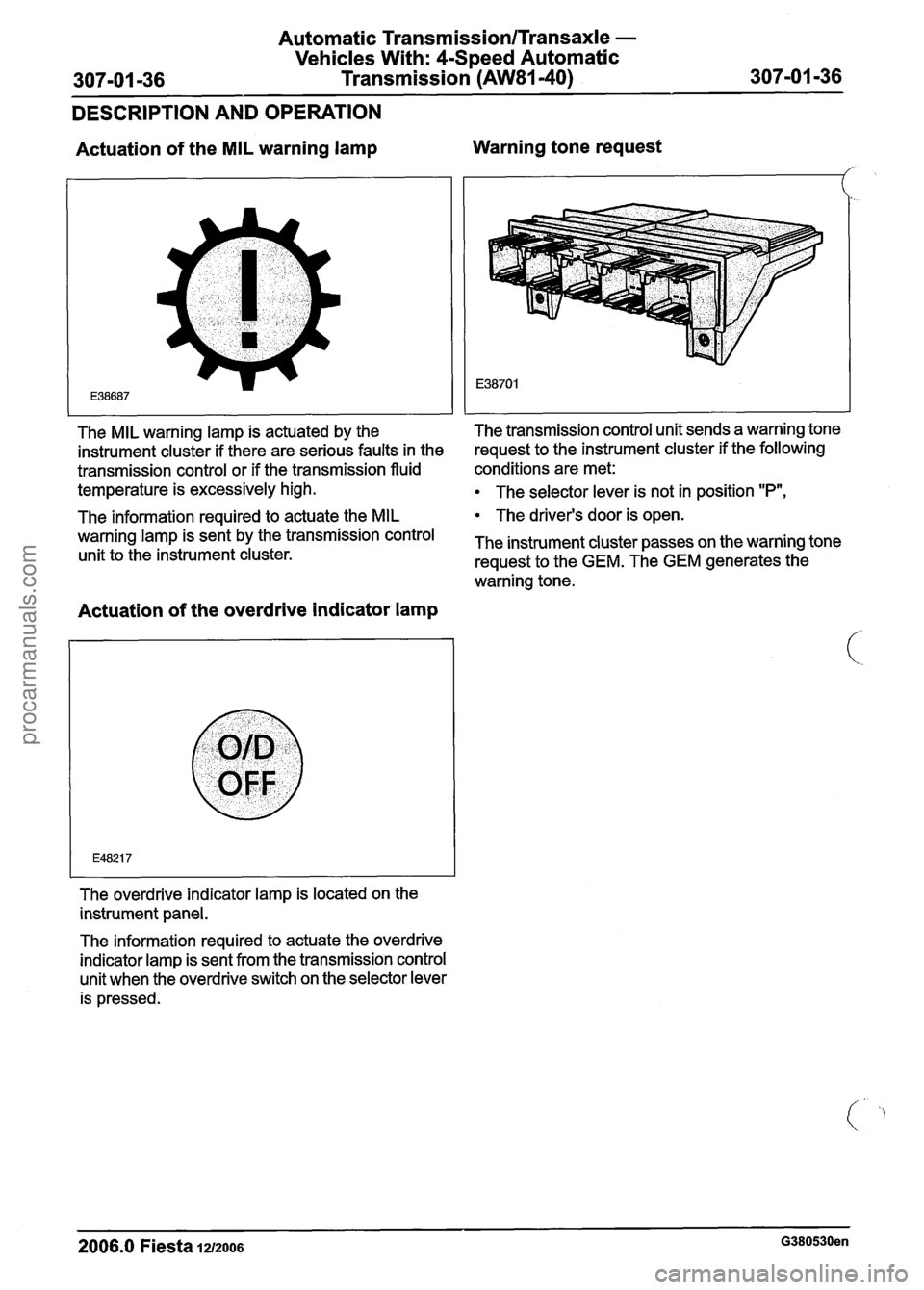
Actuation of the MIL warning lamp Warning tone request
The information required to actuate the
MIL The
driver's door is open.
warning lamp is sent the transmission control The instrument cluster passes on the warning tone unit to the instrument cluster.
request to the GEM. The GEM generates the
warning tone.
I I I
Actuation of the overdrive indicator lamp
I
The overdrive indicator lamp is located on the
instrument panel.
The MIL warning lamp
is actuated by the The transmission control unit sends
a warning tone
instrument cluster if there are serious faults in the request
to the instrument cluster if the following
transmission control or if the transmission fluid conditions are
met:
temperature is excessively high.
The selector lever is not in position "P",
The information required to actuate the overdrive
indicator lamp is sent from the transmission control
unit when the overdrive switch on the selector lever
is pressed.
2006.0 Fiesta 1u2oos G380530en
procarmanuals.com
Page 999 of 1226
Automatic Transmission/Transaxle -
Vehicles With: 4-Speed Automatic
307-01 -39 Transmission (AW81-40) 307-01 -39
DESCRIPTION AND OPERATION
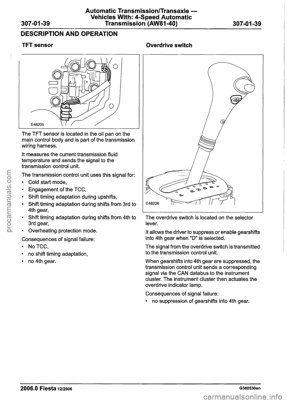
TFT sensor Overdrive switch
The TFT sensor is located in the oil pan on the
main control body and is part of the transmission
wiring harness.
It measures the current transmission fluid
temperature and sends the signal to the
transmission control unit.
The transmission control unit uses this signal for:
Cold start mode,
Engagement of the TCC,
Shift timing adaptation during upshifts,
' , Shift timing adaptation during shifts from 3rd to
4th gear,
Shift timing adaptation during shifts from 4th to
3rd gear,
Overheating protection mode.
Consequences of signal failure:
NoTCC,
no shift timing adaptation,
no 4th gear. The overdrive switch
is located on the selector
lever.
It allows the driver to suppress or enable gearshifts
into 4th gear when
"D" is selected.
The signal from the overdrive switch is transmitted
to the transmission control unit.
When gearshifts into 4th gear are suppressed, the
transmission control unit sends a corresponding
signal via the CAN
databus to the instrument
cluster. The instrument cluster then actuates the
overdrive indicator lamp.
Consequences of signal failure:
no suppression of gearshifts into 4th gear.
2006.0 Fiesta 1212006 G380530en
procarmanuals.com
Page 1005 of 1226
Automatic Transmission/Transaxle -
Vehicles With: 4-Speed Automatic Transmission
(AW81-40)
DIAGNOSIS AND TESTING
Automatic Transaxle
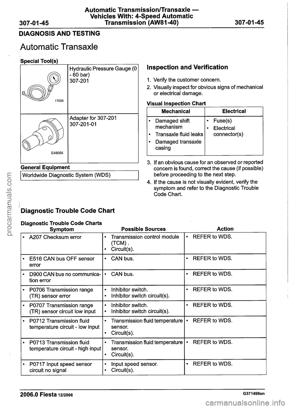
Special Tool(s)
Hydraulic Pressure Gauge (0
- 60 bar)
307-20 1
General Equipment Worldwide
~ia~noitic System (WDS)
Inspection and Verification
1. Verify the customer concern.
2. Visually inspect for obvious signs of mechanical
or electrical damage.
Visual
lns~ection Chart
I Mechanical I Electrical I
3. If an obvious cause for an observed or reported
concern is found, correct the cause (if possible)
before proceeding to the next step.
4. If the cause is not visually evident, verify the
symptom and refer to the Diagnostic Trouble
Code Chart.
Damaged shift
mechanism
Transaxle fluid leaks
Damaged transaxle
casing
.I
- Diagnostic Trouble Code Chart
Fuse(s)
Electrical
connector(s)
Diagnostic Trouble Code Charts
Symptom Possible Sources Action
I A207 Checksum error I Transmission control module I REFER to WDS.
E516 CAN bus OFF sensor
error CAN bus.
D9OO CAN bus no communica-
tion error
PO706 Transmission range
(TR) sensor error
PO707 Transmission range
(TR) sensor circuit low input
CAN bus.
Inhibitor switch.
Inhibitor switch circuit(s).
lnhibitor switch.
lnhibitor switch circuit(s).
PO712 Transmission fluid
temperature circuit
- low input
REFER to WDS.
REFER to WDS.
3 Transmission fluid
temperature circuit
- high input
2006.0 Fiesta 1212006 G371498en
Transmission fluid temperature
sensor.
Circuit(s).
PO71 7 lnput speed sensor
circuit no signal
REFER to WDS.
Transmission fluid temperature
sensor.
e Circuit(s).
lnput speed sensor.
Circuit(s).
REFER to WDS.
procarmanuals.com
Page 1008 of 1226
Automatic TransmissionlTransaxle -
Vehicles With: 4-Speed Automatic
307-01 -48 Transmission (AW81-40) 307-01 -48
DIAGNOSIS AND TESTING
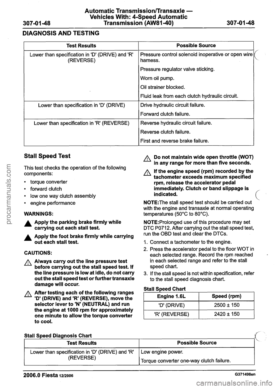
Stall Speed Test
This test checks the operation of the following
components:
1
Test Results
Lower than specification in 'Dl (DRIVE) and 'R'
(REVERSE)
Lower than specification in
'Dl (DRIVE)
Lower than specification in
'R' (REVERSE)
torque converter
forward clutch
low one way clutch assembly
engine performance
Possible Source
Pressure control solenoid inoperative or open wire
harness.
Pressure regulator valve sticking.
Worn oil pump.
Oil strainer blocked.
Fluid leak from each clutch hydraulic circuit.
Drive hydraulic circuit failure.
Forward clutch failure.
Reverse hydraulic circuit failure. Reverse clutch failure.
First and reverse brake failure.
WARNINGS:
A Do not maintain wide open throttle (WOT)
in any range for more than five seconds.
A If the engine speed (rpm) recorded by the
tachometer exceeds maximum specified
rpm, release the accelerator pedal
immediately. Clutch or band slippage is
indicated.
N0TE:The stall speed test should be carried out
with the engine and transaxle at normal operating
temperatures (50°C to 80°C).
A Apply the parking brake firmly while N0TE:Prolonged use of this procedure may set
carrying out each stall test. DTC PO71 2. After carrying out the stall speed test,
A Apply the foot brake firmly while carrying run the OBD test and clear the DTCs.
out each stall test. I. Connect a tachometer to the engine.
CAUTIONS:
A Always carry out the line pressure test
before carrying out the stall speed test. If
the line pressure is low at idle, do not carry
out the stall speed test or further transaxle
damage will occur.
A After testing each of the following ranges
'D'
(DRIVE) and 'R' (REVERSE), move the
selector lever to
'N' (NEUTRAL) and run
the engine at 1000 rpm for approximately
one minute to allow the torque converter
to cool.
2. Press the accelerator pedal to the floor WOT in
each selected range. Record the rpm reached
in each selected range and refer to the stall
speed chart.
3. If the stall speed is not within specification, refer
to the stall speed diagnosis chart.
Stall S~eed Chart
I Engine 1.6L I Speed (rpm) I
I 'Dl (DRIVE) I 2500 2 150 1
'R' (REVERSE) 2420 +, 150 -
Stall
Speed Diagnosis Chart
2006.0 Fiesta 1212006 G371498en
Test Results
Lower than specification in ID' (DRIVE) and 'R'
(REVERSE)
Possible Source
Low engine power.
Torque converter one-way clutch failure.
procarmanuals.com
Page 1009 of 1226
Automatic Transmission/Transaxle -
Vehicles With: 4-Speed Automatic
307-01 49 Transmission (AW81-40) 307-01 -49
DIAGNOSIS AND TESTING
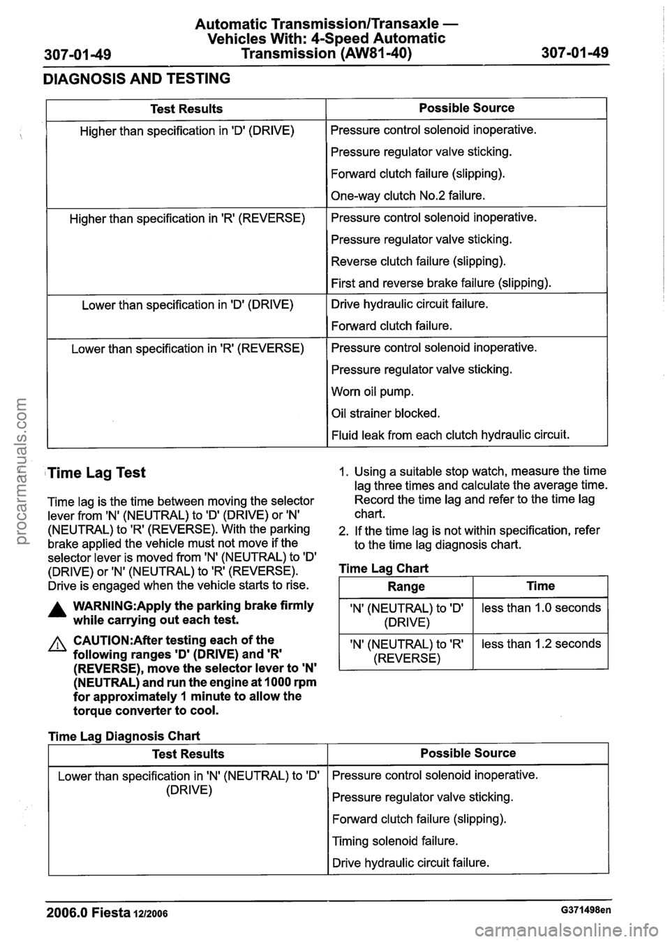
Test Results
Higher than specification in 'Dl (DRIVE)
Higher than specification in
'R' (REVERSE)
Lower than specification in 'D' (DRIVE)
Lower than specification in
'R' (REVERSE)
Possible Source
Pressure control solenoid inoperative.
Pressure regulator valve sticking.
Forward clutch failure (slipping).
One-way clutch No.2 failure.
Pressure control solenoid inoperative.
Pressure regulator valve sticking.
Reverse clutch failure (slipping).
First and reverse brake failure (slipping).
Drive hydraulic circuit failure.
Forward clutch failure.
Pressure control solenoid inoperative.
Pressure regulator valve sticking.
Worn oil pump.
Oil strainer blocked.
Fluid leak from each clutch hydraulic circuit.
( Time Lag Test 1. Using a suitable stop watch, measure the time
lag three times and calculate the average time.
Time lag is the time between moving the selector Record the
time lag and refer to the time lag
lever from
IN' (NEUTRAL) to ID' (DRIVE) or IN' chart.
(NEUTRAL) to 'R' (REVERSE). With the parking 2. If the time lag is not within specification, refer
brake applied the vehicle must not move if the
to the time lag diagnosis chart.
selector lever is moved from 'N' (NEUTRAL) to
ID'
(DRIVE) or 'N' (NEUTRAL) to 'R' (REVERSE). Time Lag Chart
Drive is engaged when the vehicle starts to rise.
A WARN1NG:Apply the parking brake firmly IN' (NEUTRAL) to ID' while carrying out each test. 1 (DRIVE)
(NEUTRAL) and run the engine at 1000 rpm
for approximately
1 minute to allow the
torque converter to cool.
less than 1.0 seconds
CAUTI0N:After testing each of the
following ranges
'D' (DRIVE) and 'R'
Range
I Lower than specification in IN' (NEUTRAL) to 'Dl I Pressure control solenoid inoperative.
Ti me
(REVERSE), move the selector lever to 'N'
'N' (NEUTRAL) to 'R'
(REVERSE)
Time Lag Diagnosis Chart
(DRIVE) less
than 1.2 seconds
Test Results
Pressure regulator valve sticking.
Forward clutch failure (slipping).
Possible Source
I Timing solenoid failure.
I I Drive hydraulic circuit failure. I
2006.0 Fiesta IZIZOO~ G371498en
procarmanuals.com
Page 1011 of 1226
Automatic Transmission/Transaxle -
Vehicles With: 4-Speed Automatic
307-01 -51 Transmission (AW81-40) 307-01 -51 -
GENERAL PROCEDURES
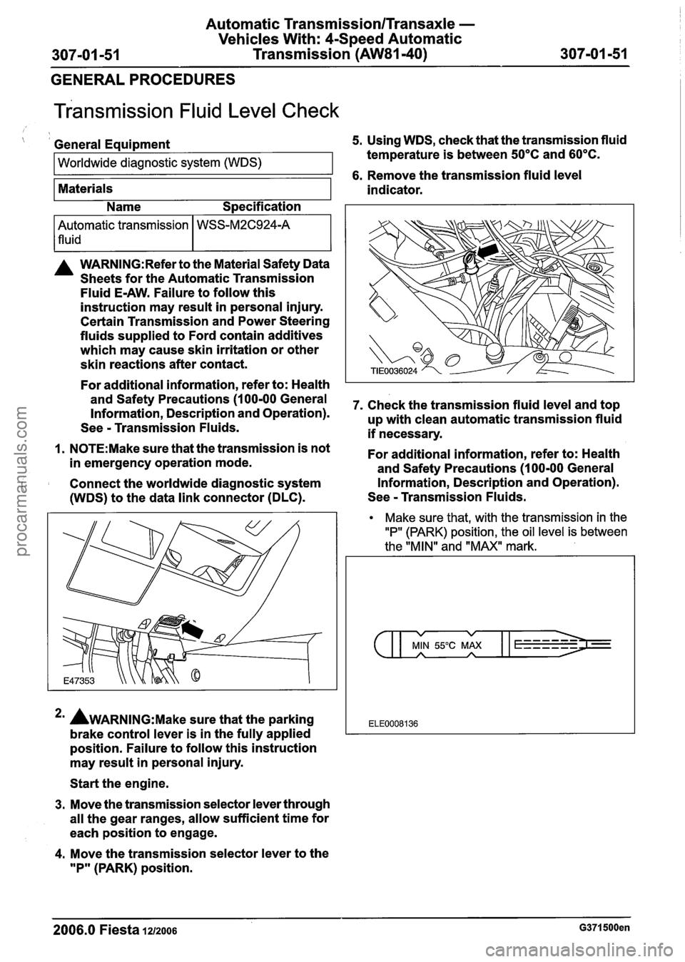
~ransmission Fluid Level Check
( I General Equipment 5. Using WDS, check that the transmission fluid
Worldwide diagnostic system (WDS) temperature is between 50°C and 60°C.
1 6. Remove the transmission fluid level
Materials
A WARN1NG:Refer to the Material Safety Data
Sheets for the Automatic Transmission
Fluid
E-AW. Failure to follow this
instruction may result in personal injury.
Certain Transmission and Power Steering
fluids supplied to Ford contain additives
which may cause skin irritation or other
skin reactions after contact.
For additional information, refer to: Health
and Safety Precautions (1 00-00 General
Information, Description and Operation).
See
- Transmission Fluids.
1. N0TE:Make sure that the transmission is not
in emergency operation mode.
Connect the worldwide diagnostic system
(WDS) to the data link connector (DLC). indicator.
Automatic transmission
lfluid
*' AWARNING:M~~~ sure that
the parking
brake control lever is in the fully applied
position. Failure to follow this instruction
may result in personal injury.
Name
Specification
WSS-M2C924-A
Start the engine.
3. Move the transmission selector lever through
all the gear ranges, allow sufficient time for
each position to engage.
4. Move the transmission selector lever to the
"P" (PARK) position. 7.
Check the transmission fluid level and top
up with clean automatic transmission fluid
if necessary.
For additional information, refer to: Health
and Safety Precautions (1 00-00 General
Information, Description and Operation).
See
- Transmission Fluids.
Make sure that, with the transmission in the
"P" (PARK) position, the oil level is between
the "MIN" and "MAX" mark.
v v
MIN 55°C MAX A A
ELE0008136
2006.0 Fiesta 1212006 G371500en
procarmanuals.com
Page 1012 of 1226
Automatic Transmission/Transaxle -
Vehicles With: CSpeed Automatic
307-01 -52 Transmission (AW81-40) 307-01 -52
GENERAL PROCEDURES
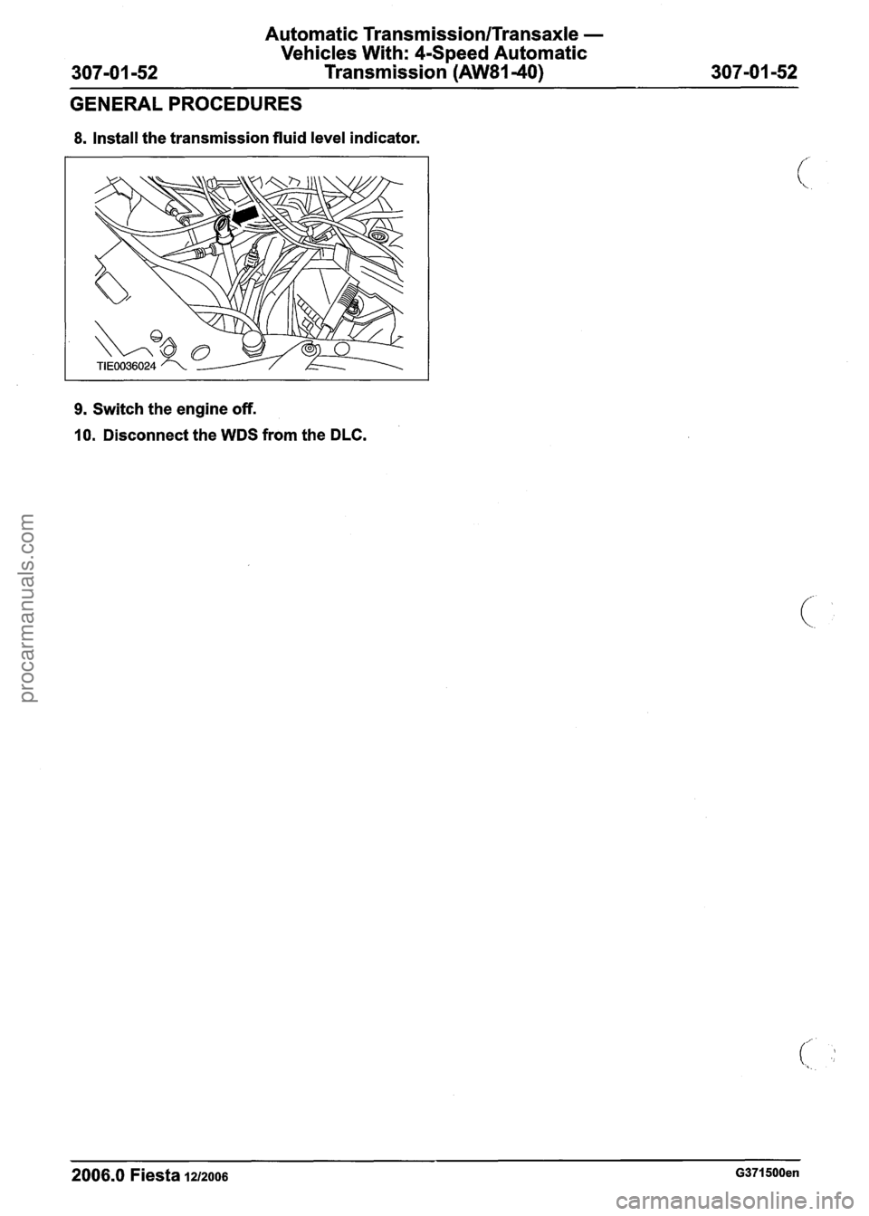
8. Install the transmission fluid level indicator.
9. Switch the engine off.
10. Disconnect the WDS from the DLC.
2006.0 Fiesta 1212006 G371500en
procarmanuals.com
Page 1013 of 1226
Automatic Transmission/Transaxle -
Vehicles With: 4-Speed Automatic
307-01 -53 Transmission (AW81-40)
307-01 -53
GENERAL PROCEDURES
Transmission Fluid Drain and Refill
I I Name Specification
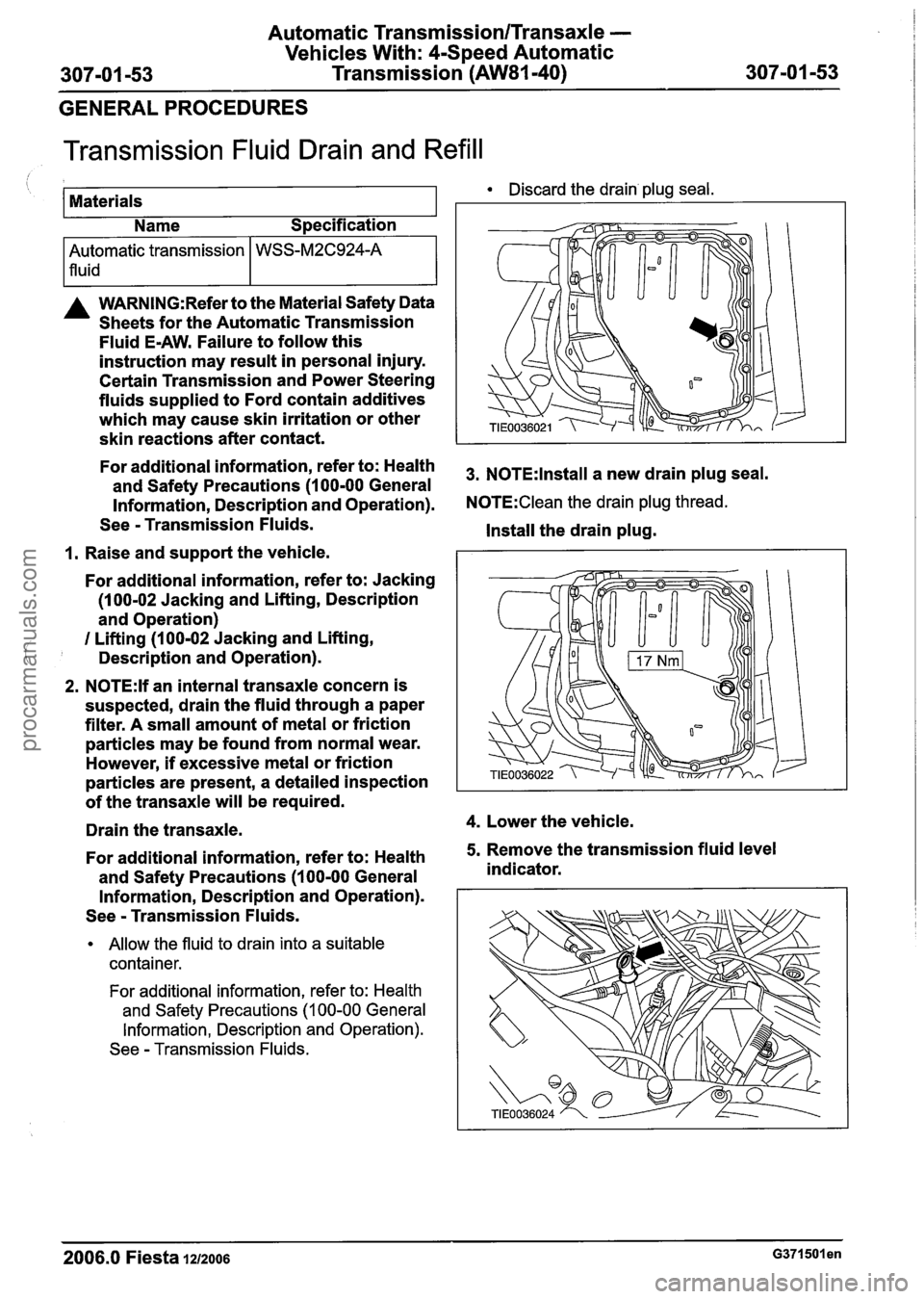
Discard the drain plug seal.
1 Materials
--
A WARNING:Refer to the Material Safety Data
Sheets for the Automatic Transmission
Fluid
E-AW. Failure to follow this
instruction may result in personal injury.
Certain Transmission and Power Steering
fluids supplied to Ford contain additives
which may cause skin irritation or other
skin reactions after contact.
I I
Automatic transmission
lfluid-
For additional information, refer to: Health 3, NOTE:lnstall a new drain plug seal. and Safety Precautions (1 00-00 General
Information, Description and Operation).
N0TE:Clean the drain plug thread.
See - Transmission Fluids.
Install the drain plug.
1. Raise and support the vehicle.
WSS-M2C924-A
For additional information, refer to: Jacking
(1 00-02 Jacking and Lifting, Description
and Operation)
I Lifting (100-02 Jacking and Lifting,
Description and Operation).
2. N0TE:lf an internal transaxle concern is
suspected, drain the fluid through a paper
filter. A small amount of metal or friction
particles may be found from normal wear.
However,
if excessive metal or friction
particles are present, a detailed inspection
of the transaxle will be required.
Drain the transaxle.
4. Lower the vehicle.
For additional information, refer to: Health
5. Remove the transmission fluid level
and Safety Precautions
(1 00-00 General indicator.
Information, Description and Operation).
See
- Transmission Fluids.
Allow the fluid to drain into a suitable
container.
For additional information, refer to: Health
and Safety Precautions
(1 00-00 General
Information, Description and Operation).
See
- Transmission Fluids.
2006.0 Fiesta 1212006 ~371501 en
procarmanuals.com