torque FORD FIESTA 2007 User Guide
[x] Cancel search | Manufacturer: FORD, Model Year: 2007, Model line: FIESTA, Model: FORD FIESTA 2007Pages: 1226, PDF Size: 61.26 MB
Page 226 of 1226
206-04-2 Rear Disc Brake 206-04-2
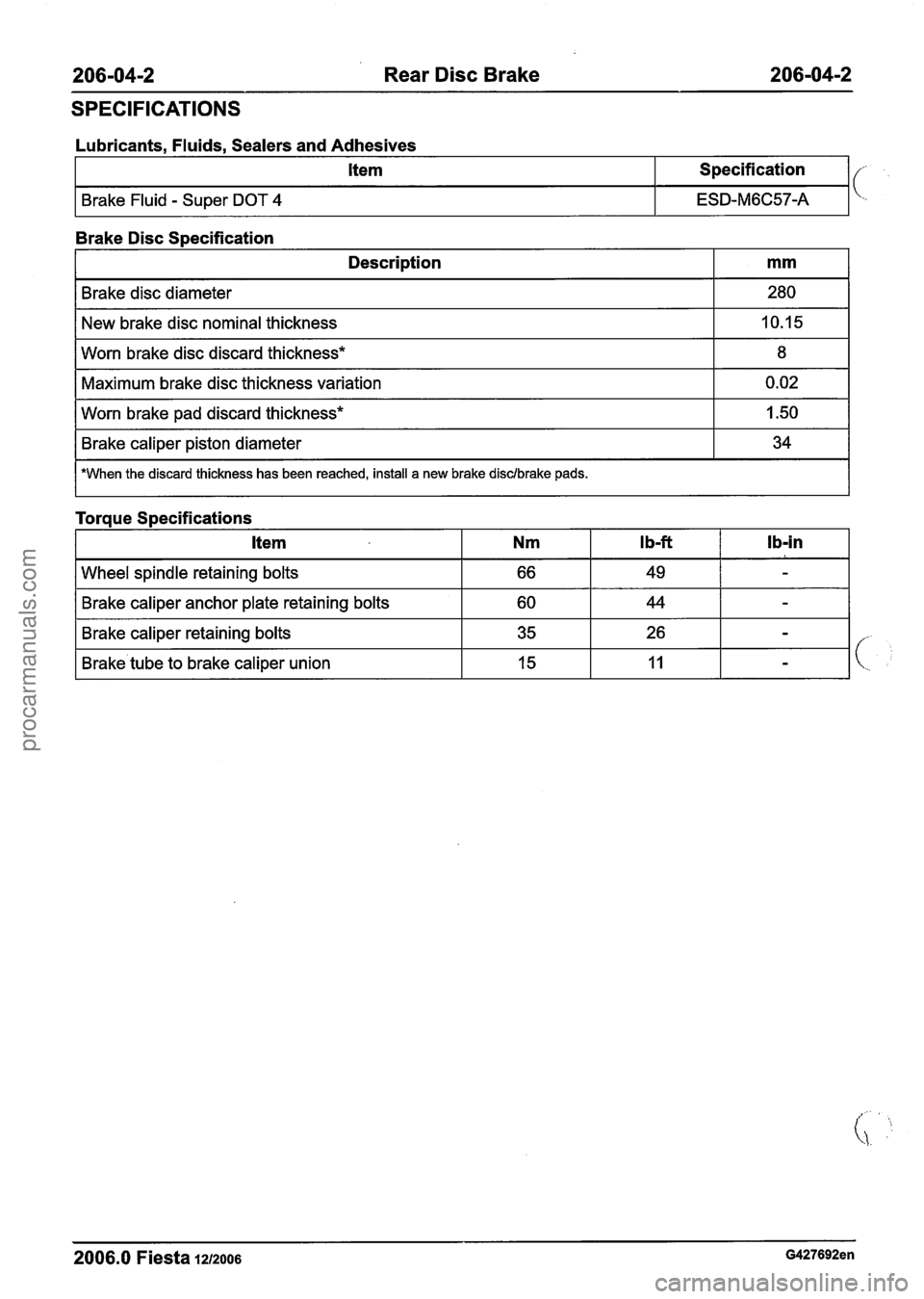
SPECIFICATIONS
Lubricants, Fluids, Sealers and Adhesives
Item Specification
ESD-M6C57-A
Brake Disc S~ecification
I Description I mm I
Brake disc diameter
New brake disc nominal thickness
I Worn brake pad discard thickness* I 1.50 1
280
10.15
Worn brake disc discard thickness*
Maximum brake disc thickness variation
I Brake caliper piston diameter I 34 I
8
0.02
I *When the discard thickness has been reached, install a new brake disdbrake pads.
-spindle retaining bolts I 66 I 49 I - I
Torque Specifications
I Brake caliper anchor plate retaining bolts I 60 I 44 I - I
I Brake caliper retaining bolts I 35 I 26 I - I
Ib-in Item
I Brake.tube to brake caliper union I 15 I 11 I - I
2006.0 Fiesta 1u2oo6 G427692en
Nm Ib-ft
procarmanuals.com
Page 238 of 1226
206-05-2 Parking Brake and Actuation 206-05-2
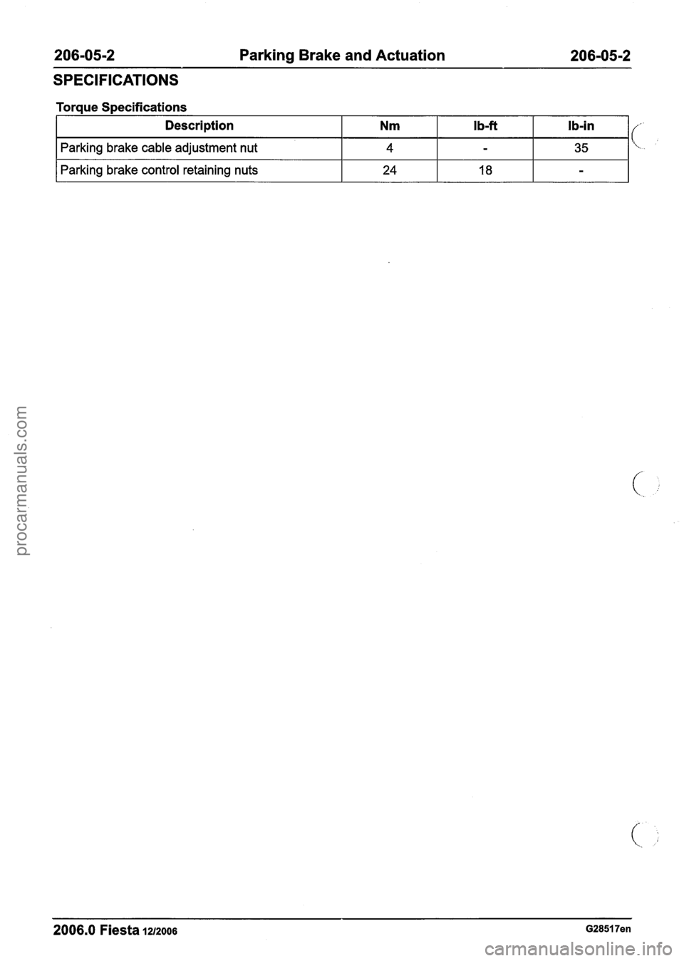
SPECIFICATIONS
Torque Specifications
I Parking brake control retaining nuts I 24 I 18 I - I
Description Nm I b-ft Ib-in
Parking brake cable adjustment nut 4 - 35
-
2006.0 Fiesta 1212006 G28517en
(' L..
procarmanuals.com
Page 245 of 1226
206-05-9 Parking Brake and Actuation 206-05-9
GENERAL PROCEDURES
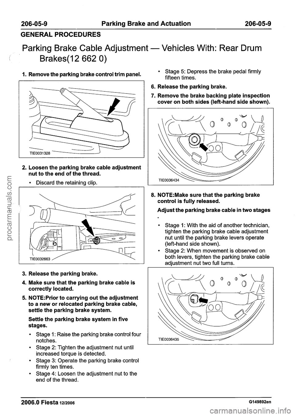
Parking Brake Cable Adjustment - Vehicles With: Rear Drum
I. Remove the parking brake control trim panel. Stage 5: Depress the brake pedal firmly
fifteen times.
2. Loosen the parking brake cable adjustment
nut to the end of the thread.
Discard the retaining clip.
3. Release the parking brake.
4. Make sure that the parking brake cable is
correctly located.
5. N0TE:Prior to carrying out the adjustment
to a new or relocated parking brake cable,
settle the parking brake system.
Settle the parking brake system in five
stages.
Stage 1 : Raise the parking brake control four
notches.
Stage 2: Tighten the adjustment nut until
increased torque is detected.
Stage 3: Operate the parking brake control
firmly ten times.
Stage 4: Loosen the adjustment nut to the
end of the thread.
6. Release the parking brake.
7. Remove the brake backing plate inspection
cover on both sides (left-hand side shown).
8. N0TE:Make sure that the parking brake
control is fully released.
Adjust the parking brake cable in two stages
Stage 1 : With the aid of another technician,
tighten the parking brake cable adjustment
nut until the parking brake levers operate
(left-hand side shown).
Stage 2: When movement is observed on
both levers, tighten the parking brake cable
adjustment nut two full turns.
2006.0 Fiesta 1212006 GI 49892en
procarmanuals.com
Page 247 of 1226
206-05-1 1 Parking Brake and Actuation 206-05-1 1
GENERAL PROCEDURES
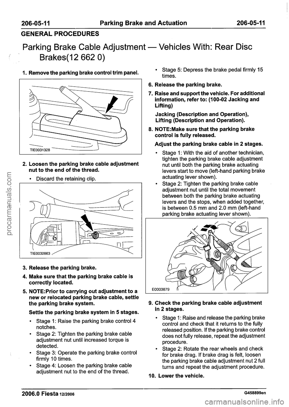
Parking Brake Cable Adjustment - Vehicles With: Rear Disc
1. Remove the parking brake control trim panel. Stage 5: Depress the brake pedal firmly 15
times.
6. Release the parking brake.
7. Raise and support the vehicle. For additional
information, refer to: (1
00-02 Jacking and
Lifting)
Jacking (Description and Operation),
Lifting (Description and Operation).
8. N0TE:Make sure that the parking brake
control is fully released.
Adjust the parking brake cable in
2 stages.
Stage 1 : With the aid of another technician,
tighten the parking brake cable adjustment
2.
Loosen the parking brake cable adjustment nut until both the parking brake actuating
nut to the end of the thread. levers start to move (left-hand parking brake
Discard the retaining clip. actuating lever
shown). Stage 2: Tighten the parking brake cable
adjustment nut until the total movement
between both the parking brake actuating
levers and the stops, when added together,
is between 0.5 mm and 2.0 mm (left-hand
parking brake actuating lever shown).
3. Release the parking brake.
4. Make sure that the parking brake cable is
correctly located.
5. N0TE:Prior to carrying out adjustment to a
new or relocated parking brake cable, settle
the parking brake system.
9. Check the parking brake cable adjustment
Settle the parking brake system in
5 stages.
Stage 1 : Raise the parking brake control 4
notches.
Stage 2: Tighten the parking brake cable
adjustment nut until increased torque is
detected.
Stage 3: Operate the parking brake control
firmly
10 times.
Stage 4: Loosen the parking brake cable
adjustment nut to the end of the thread.
in 2 stages.
Stage 1 : Raise and release the parking brake
control and check that it returns to the fully
released position. If the parking brake control
does not fully release, repeat the adjustment
procedure.
Stage 2: Rotate the rear wheels and check
for brake drag. If brake drag is felt, loosen
the parking brake cable adjustment nut 2 full
turns and repeat the adjustment procedure.
10. Lower the vehicle.
2006.0 Fiesta 1212006 G458899en
procarmanuals.com
Page 256 of 1226
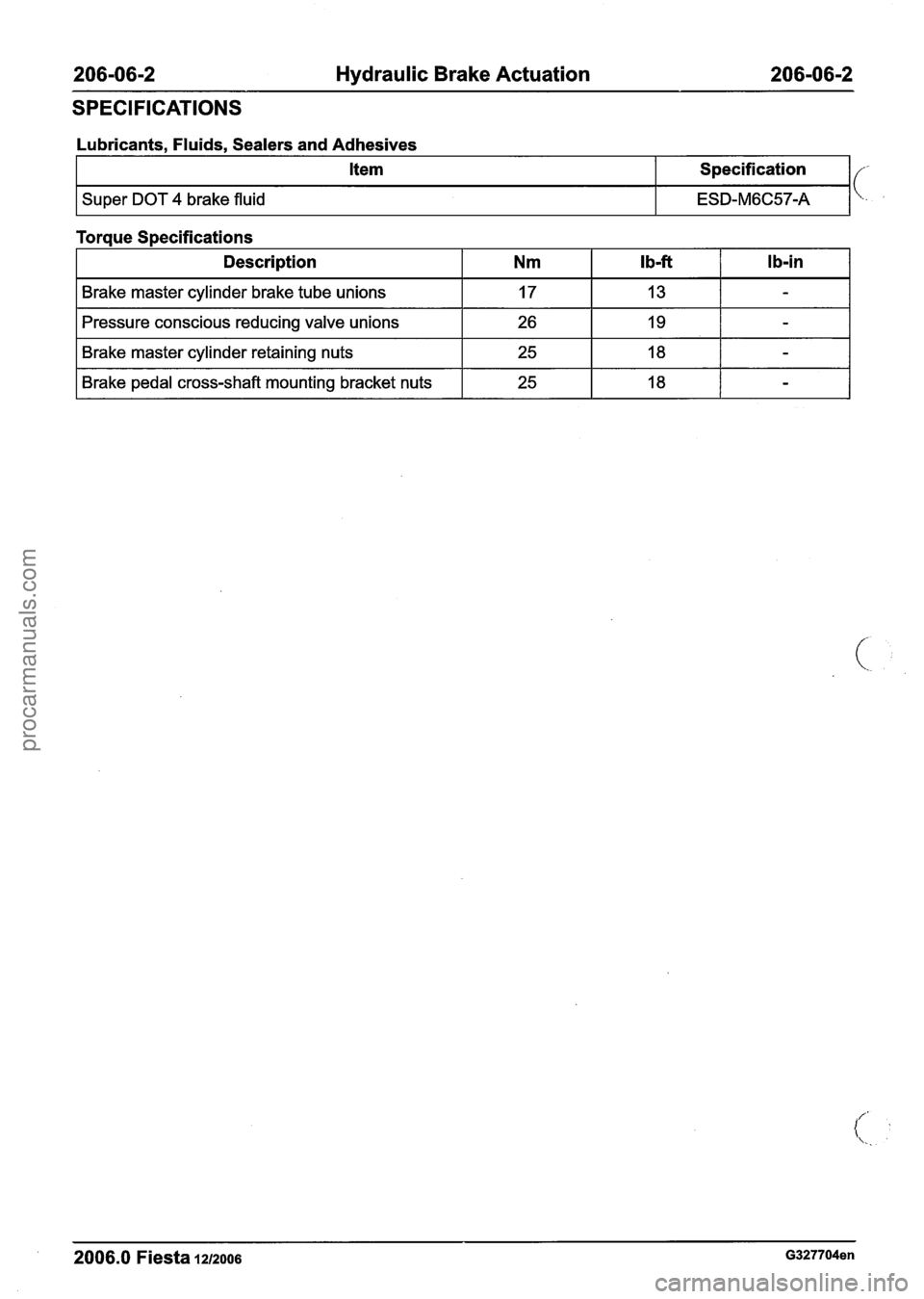
206-06-2 Hydraulic Brake Actuation 206-06-2
SPECIFICATIONS
Lubricants. Fluids. Sealers and Adhesives
Torque Specifications
Item
Super DOT 4 brake fluid
I Description I Nm I Ib-ft I Ib-in I
Specification
ESD-M6C57-A
I Brake master cylinder brake tube unions I 17 I 13 I - I
I Brake master cylinder retaining nuts I 25 I 18 I - I
Pressure conscious reducing valve unions
-- - -
I Brake pedal cross-shaft mounting bracket nuts I 25
2006.0 Fiesta 1212006 G327704en
26 19 -
procarmanuals.com
Page 266 of 1226
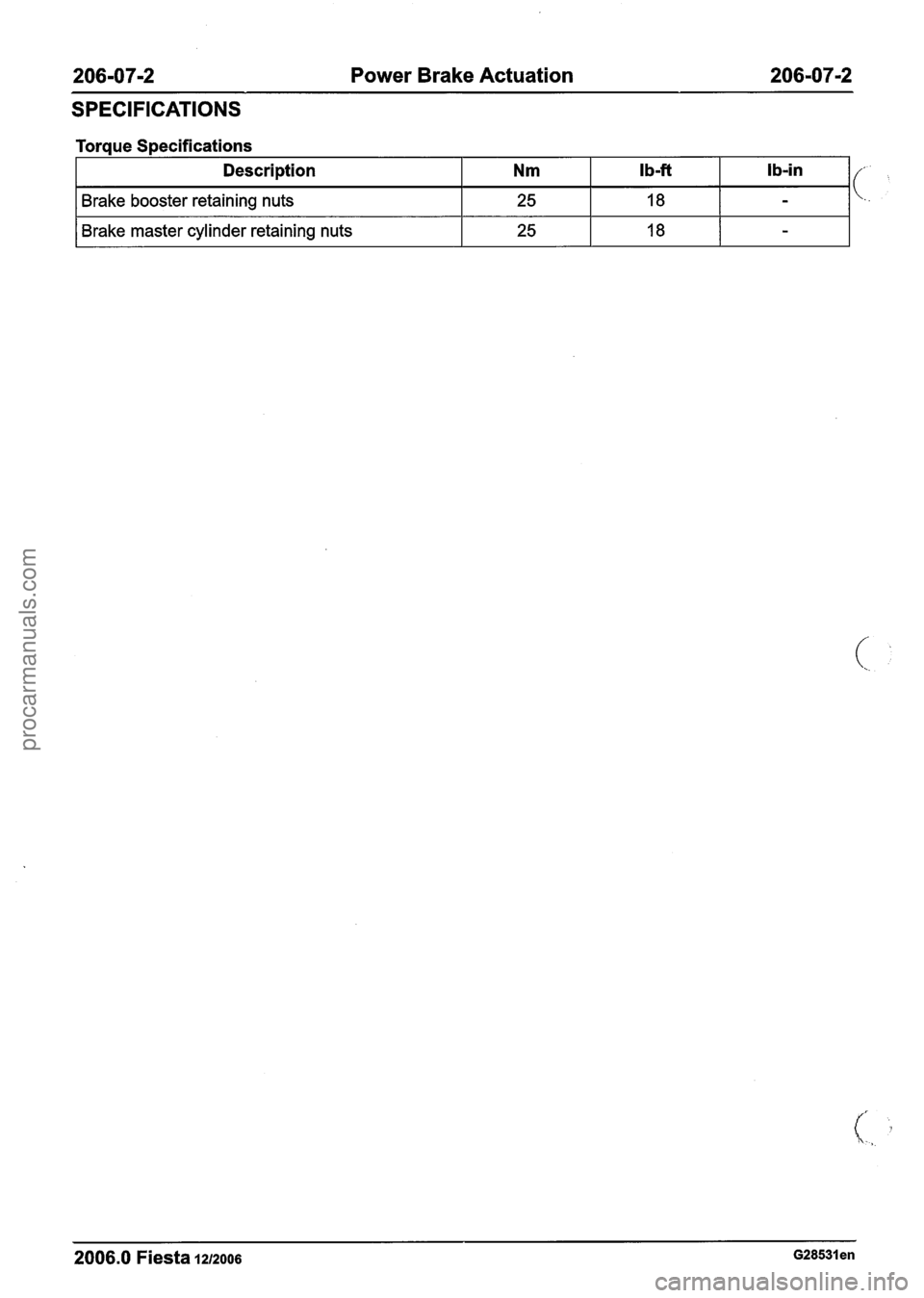
206-07-2 Power Brake Actuation 206-07-2
SPECIFICATIONS
Torque Specifications
I Brake master cylinder retaining nuts I 25 I 18 I - I
Description
Brake booster retaining nuts
2006.0 Fiesta 1212006 ~28531 en
Nm
25
Ib-ft
18
lb-in
-
procarmanuals.com
Page 300 of 1226
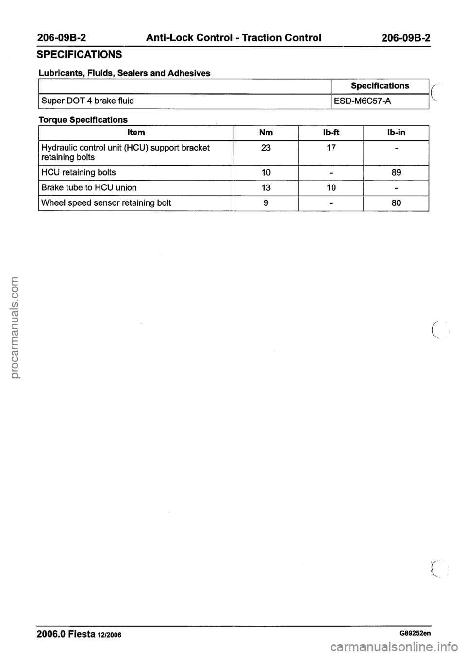
206-09B-2 Anti-Lock Control - Traction Control 206-09B-2
SPECIFICATIONS
Lubricants, Fluids, Sealers and Adhesives
I I Specifications I {-
I Super DOT 4 brake fluid I ESD-M6C57-A 1 \.,
Torque S~ecifications
Hydraulic control unit (HCU) support bracket
retaining bolts
2006.0 Fiesta 1212006 G89252en
HCU retaining bolts
Brake tube to HCU union
Wheel speed sensor retaining bolt 23 10
13
9 17
-
-
10
-
89
-
80
procarmanuals.com
Page 308 of 1226
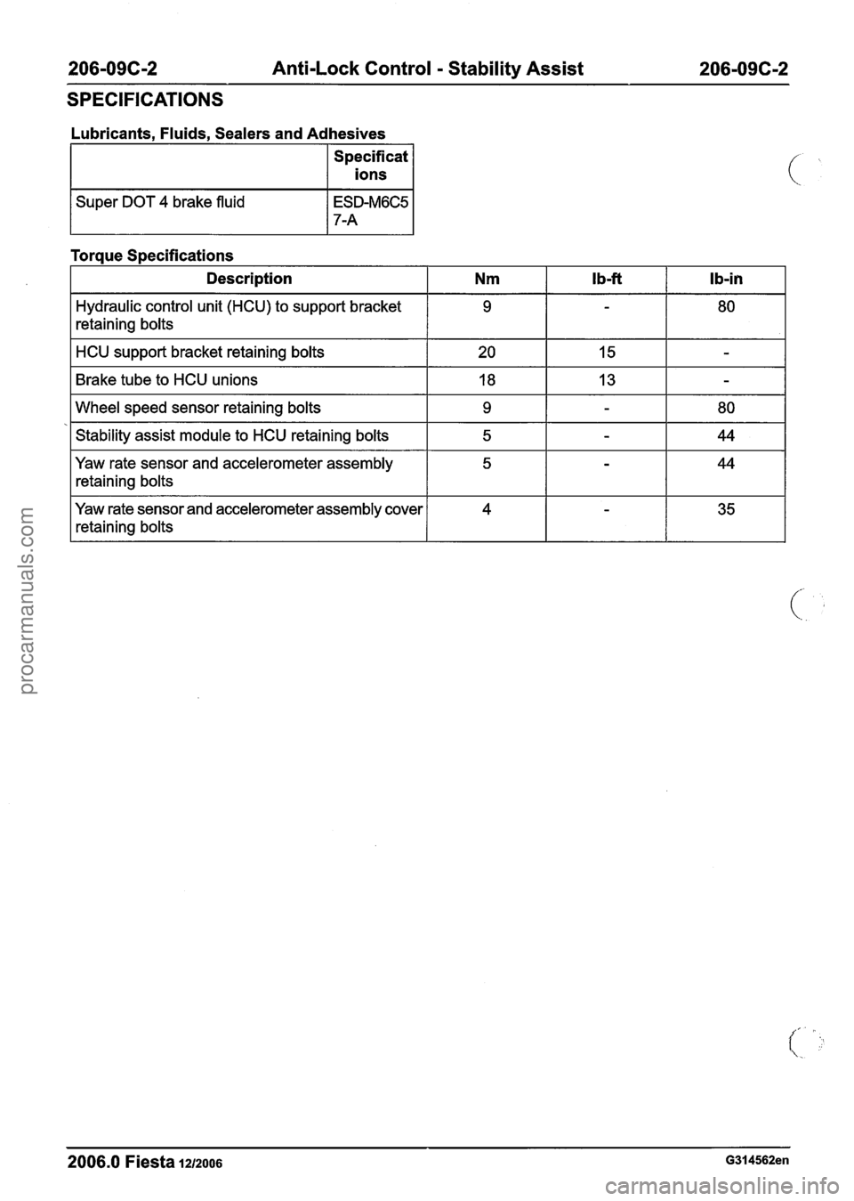
206-09C-2 Anti-Lock Control - Stability Assist 206-096-2
SPECIFICATIONS
Lubricants, Fluids, Sealers and Adhesives
Specificat
I ions 1
/ Super DOT 4 brake fluid
Torque Specifications
Description
I Nm I Ib-ft I Ib-in I
HCU support bracket retaining bolts I 20 I 15 I - I
Hydraulic control unit (HCU) to support bracket
retaining bolts
Brake tube to HCU unions
I 18 I 13 I - I
9
Wheel speed sensor retaining bolts I 9 I - I 80 I
Stability assist module to HCU retaining bolts I 5 I - I 44 I
2006.0 Fiesta 12/2006 G314562en
Yaw rate sensor and accelerometer assembly
retaining bolts
Yaw rate sensor and accelerometer assembly cover
retaining bolts 5
4
-
-
44
35
procarmanuals.com
Page 336 of 1226
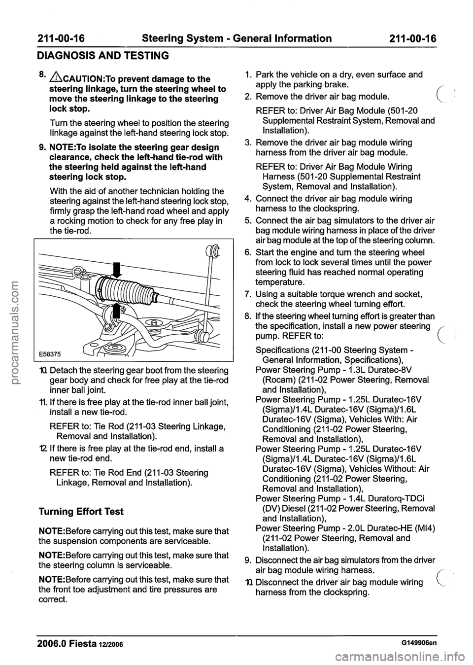
21 1-00-1 6 Steering System - General Information 21 I -00-1 6
DIAGNOSIS AND TESTING
8m ACAUTION:T~ prevent damage to the
steering linkage, turn the steering wheel to
move the steering linkage to the steering
lock stop.
Turn the steering wheel to position the steering
linkage against the left-hand steering lock stop.
9. N0TE:To isolate the steering gear design
'clearance, check the left-hand
tiemrod with
the steering held against the left-hand
steering lock stop.
With the aid of another technician holding the
steering against the left-hand steering lock stop,
firmly grasp the left-hand road wheel and apply
a rocking motion to check for any free play in
the tie-rod.
IQ Detach the steering gear boot from the steering
gear body and check for free play at the tie-rod
inner ball joint.
11. If there is free play at the tie-rod inner ball joint,
install a new tie-rod.
REFER to: Tie Rod (211-03 Steering Linkage,
Removal and lnstallation).
I2 If there is free play at the tie-rod end, install a
new tie-rod end.
REFER to: Tie Rod End (21 1-03 Steering
Linkage, Removal and lnstallation).
Turning Effort Test
N0TE:Before carrying out this test, make sure that
the suspension components are serviceable.
N0TE:Before carrying out this test, make sure that
the steering column is serviceable.
N0TE:Before carrying out this test, make sure that
the front toe adjustment and tire pressures are
correct. 1.
Park the vehicle on a dry, even surface and
apply the parking brake.
/- ,
2. Remove the driver air bag module.
REFER to: Driver Air Bag Module (501 -20
Supplemental Restraint System, Removal and
Installation).
3. Remove the driver air bag module wiring
harness from the driver air bag module.
REFER to: Driver Air Bag Module Wiring
Harness (501 -20 Supplemental Restraint
System, Removal and Installation).
4. Connect the driver air bag module wiring
harness to the clockspring.
5. Connect the air bag simulators to the driver air
bag module wiring harness in place of the driver
air bag module at the top of the steering column.
6. Start the engine and turn the steering wheel
from lock to lock several times until the power
steering fluid has reached normal operating
temperature.
7. Using a suitable torque wrench and socket,
check the steering wheel turning effort.
8. If the steering wheel turning effort is greater than
the specification, install a new power steering -
pump. REFER to: i
Specifications (21 1-00 Steering System -
General Information, Specifications),
Power Steering Pump
- I .3L Duratec-8V
(Rocam) (21 1-02 Power Steering, Removal
and lnstallation),
Power Steering Pump
- 1.25L Duratec-1 6V
(Sigma)/l.4L Duratec-1 6V (Sigma)/l .6L
Duratec-l6V (Sigma), Vehicles With: Air
Conditioning (21 1-02 Power Steering,
Removal and lnstallation),
Power Steering Pump
- I .25L Duratec-I 6V
(Sigma)/l.4L Duratec-1 6V (Sigma)/l .6L
Duratec-I 6V (Sigma), Vehicles Without: Air
Conditioning (21 1-02 Power Steering, Removal and lnstallation),
Power Steering Pump
- 1.4L Duratorq-TDCi
(DV) Diesel (21 1-02 Power Steering, Removal
and lnstallation),
Power Steering Pump
- 2.OL Duratec-HE (M14)
(21 1-02 Power Steering, Removal and
Installation).
Disconnect the air bag simulators from the driver
air bag module wiring harness.
//
IQ Disconnect the driver air bag module wiring i,,.
harness from the clockspring.
2006.0 Fiesta 1212006 GI 49906en
procarmanuals.com
Page 338 of 1226
211 -00-1 8 Steering System - General Information 211 -00-1 8
DIAGNOSIS AND TESTING
Steering Gear Checks After a Collision
f
system REFER to: Steering Gear (211-02 Power
The following list of steering gear conditions and
Steering, Removal and Installation).
the methods
of testing should be taken into ~CCOU~~ 2. Check the tightening torque of the tiemrod end when carrying out checks to the steering system:
to wheel knuckle nut.
General
Equipment TIE-RODS (.
If
the steering gear has no faults after
REFER to: Tie Rod End (21 1-03 Steering
completing the following checks, do not install
Linkage, Removal and Installation).
a new steering gear.
3. Check the tightening torque of the tie-rod end
Surface corrosion and marks on the tie-rod are
locking nut.
acceptable.
When checking for turning effort torque peaks REFER to: Tie
Rod End
(211-03 Steering
in the steering gear, turn the steering wheel from Linkage,
Removal and lnstallation).
Feeler gauge
Straight edge
steering lock-stop to steering lock
stop in CHECK FOR TURNING EFFORT TORQUE
approximately 15 seconds. PEAKS
IN THE STEERING GEAR
1.
Using a straight edge and feeler gauge, check
the tie-rods to see if they are straight. If the
distance between the tie-rod and straight edge
A steady increase of turning effort torque from
steering center to steering lock stop is
acceptable.
When checking for power steering fluid leaks,
turn the steering wheel to the steering lock stop
in approximately
10 seconds.
Noises from the power steering, for example
the power steering pump relief valve, are
acceptable. is
greater than 0.5 mm, install a new steering
Items to be observed when checking the steering gear.
STEERING GEAR HOUSING
I. Raise and support the vehicle.
REFER to: Lifting
(1 00-02 Jacking and Lifting,
Description and Operation).
2. Visually inspect the steering gear housing for
cracks and damage. If the steering gear housing
is cracked or damaged, install a new steering
gear.
REFER to: Steering Gear
(21 1-02 Power
Steering, Removal and lnstallation).
1. Lower and support the vehicle making sure that
the road wheels are just clear of the floor.
2. With the ignition switch in position
I, slowly turn
the steering wheel from steering lock stop to
steering lock stop. If a turning effort torque peak
or judder is felt while turning the steering wheel,
detach the tie-rods from the wheel knuckles.
3. Slowly turn the steering wheel from steering
lock stop to steering lock stop. If a turning effort
torque peak or judder is felt while turning the
steering wheel, install a new steering gear.
REFER to: Steering Gear
(211-02 Power
Steering, Removal and lnstallation).
CHECK FOR POWER STEERING FLUID LEAKS
1. Lower the vehicle.
2. Run the engine at a fast idle and slowly turn the
steering wheel to the left-hand steering lock
stop. Hold the steering wheel in this position for
5 seconds with a turning effort torque of
15 Nm
at the steering wheel rim.
3. Turn the steering wheel away from the left-hand
steering lock stop for 30 seconds.
4. Run the engine at a fast idle and slowly turn the
steering wheel to the right-hand steering lock
stop. Hold the steering wheel in this position for
5 seconds with a turning effort torque of
15 Nm '
at the steering wheel rim. (\,
2006.0 Fiesta 1212006 ~538091 en
procarmanuals.com