engine FORD FIESTA 2007 Workshop Manual
[x] Cancel search | Manufacturer: FORD, Model Year: 2007, Model line: FIESTA, Model: FORD FIESTA 2007Pages: 1226, PDF Size: 61.26 MB
Page 539 of 1226
Engine - 1.25L Duratec-1 6V (Sigma)ll.4L
303-01 A-63 Duratec-1 6V (Sigma)/l.6L Duratec-1 6V (Sigma) 303-01 A-63
IN-VEHICLE REPAIR
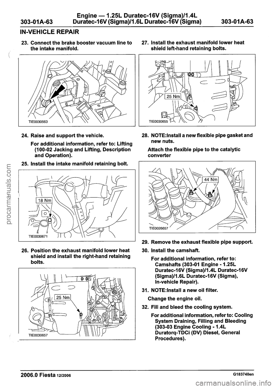
23. Connect the brake booster vacuum line to 27. Install the
exhaust manifold lower heat
the intake manifold. shield
left-hand retaining bolts.
24. Raise and support the vehicle. 28.
N0TE:lnstall a
new flexible pipe gasket and
For
additional information, refer to: Lifting new
nuts.
(1 00-02 Jacking and Lifting, Description Attach the flexible pipe to the catalytic
and Operation). converter
25.
Install the intake manifold retaining bolt.
29. Remove the exhaust flexible pipe support.
26. Position the exhaust
manifold lower heat . 30, Install the camshaft.
shield and install the right-hand retaining
For additional information, refer to:
bolts. Camshafts (303-01 Engine
- 1.25L
Duratec-1 6V (Sigma)ll.4L Duratec-1 6V
(Sigma)ll.GL Duratec-1 6V (Sigma),
In-vehicle Repair).
31.
N0TE:lnstall a new oil filter.
Change the engine oil.
32. Fill and bleed the cooling system.
For
additional information, refer to: Cooling
System Draining, Filling and Bleeding
(303-03 Engine Cooling - 1.4L
Duratorq-TDCi (DV) Diesel, General
Procedures).
2006.0 Fiesta 1212006 GI 83740en
procarmanuals.com
Page 540 of 1226
Engine - 1.25L Duratec-1 6V (Sigma)lla4L
303-01 A-64 Duratec-1 6V (Sigma)ll .6L Duratec-1 6V (Sigma) 303-01 A-64
IN-VEHICLE REPAIR
Oil Pan(21 154 0)
Special Tool(s)
Adapter for 205-047
303-633 (2
1 -227)
1501 1
General Equipment
Slide Hammer
205-047 (1 5-0 1 1 )
I Five M8 x 20 mm studs I
Materials
Name
S~ecification
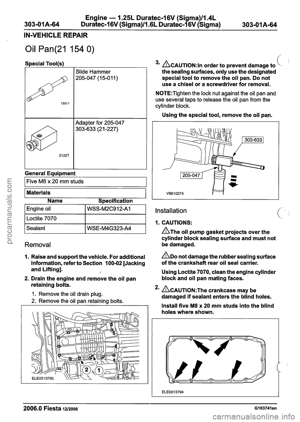
3m CAUTION:^^ order to prevent damage to
the sealing surfaces, only use the designated
special tool to remove the oil pan. Do not
use a chisel or a screwdriver for removal.
N0TE:Tighten the lock nut against the oil pan and
use several taps to release the oil pan from the
cylinder block.
Using the special tool, remove the oil pan.
Installation
1. CAUTIONS:
n~he oil pump gasket projects over the
cylinder block sealing surface and must not
Removal be damaged.
I. Raise and support the vehicle. For additional ADO not damage the rubber sealing surface
information, refer to Section 100-02 [Jacking of
the crankshaft rear oil seal carrier.
and Lifting].
I Using Loctite 7070, clean the engine cylinder
2. Drain the engine and remove the oil pan block and
oil pan mating faces.
retaining bolts.
1. Remove the oil drain plug. 2m ~CAUTION:T~~ crankcase may be
damaged
if sealant enters the blind holes. 2. Remove the oil pan retaining bolts.
I I Install five M8 x 20 mm studs into the blind
holes where shown.
2006.0 Fiesta 1212006 GI 83741 en
procarmanuals.com
Page 541 of 1226
Engine - 1.25L Duratec-1 6V (Sigma)ll.4L
303-01 A-65 Duratec-1 6V (Sigma)ll .6L Duratec-1 6V (Sigma) 303-01 A-65
IN-VEHICLE REPAIR
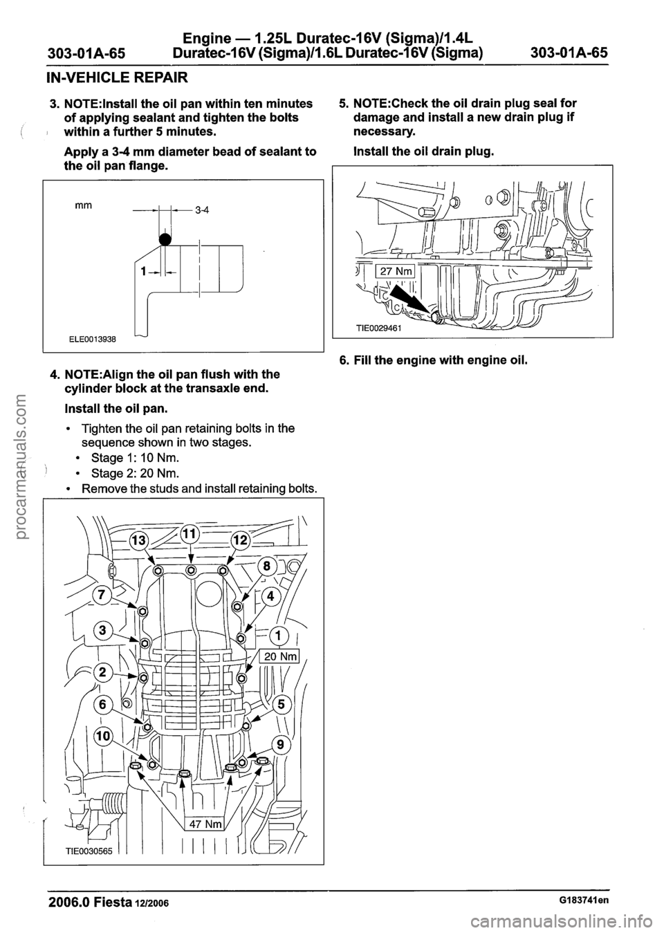
3. N0TE:lnstall the oil pan within ten minutes 5. N0TE:Check the oil drain plug seal for
of applying sealant and tighten the bolts damage
and install a new drain plug if
( I within a further 5 minutes. necessary.
Apply a 3-4 mm diameter bead of sealant to Install the oil drain plug.
the oil pan flange.
6. Fill the engine with engine oil.
4. N0TE:Align the oil pan flush with the
cylinder block at the transaxle end.
Install the oil pan.
Tighten the oil pan retaining bolts in the
sequence shown in two stages.
Stage
I : 10 Nm.
( I Stage2:20Nm.
Remove the studs and install retaining bolts.
2006.0 Fiesta 1212006 GI 83741 en
procarmanuals.com
Page 542 of 1226
Engine - 1.25L Duratec-1 6V (Sigma)llm4L
303-01 A-66 Duratec-1 6V (Sigma)/l.GL Duratec-1 6V (Sigma) 303-01 A-66
IN-VEHICLE REPAIR
Oil Pump(21 714 0)
Special Tool(s)
Removal
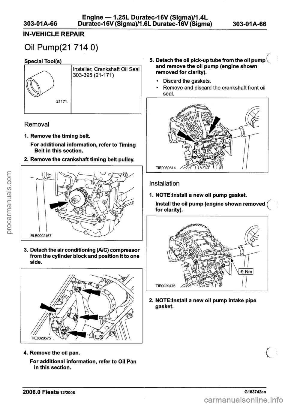
1. Remove the timing belt.
For additional information, refer to Timing
Belt in this section.
2. Remove the crankshaft timing belt pulley.
3. Detach the air conditioning (AIC) compressor
from the cylinder block and position
it to one
side.
4. Remove the oil pan.
For additional information, refer to Oil Pan
in this section.
5. Detach the oil pick-up tube from the oil pump
and remove the oil pump (engine shown
removed for clarity).
Discard the gaskets.
Remove and discard the crankshaft front oil
seal.
Installation
1. N0TE:lnstall a new oil pump gasket.
Install the oil pump (engine shown removed
for clarity).
2. N0TE:lnstall a new oil pump intake pipe
gasket.
2006.0 Fiesta 1212006 GI 83742en
procarmanuals.com
Page 543 of 1226
Engine - 1.25L Duratec-1 6V (Sigma)llI4L
303-01 A-67 Duratec-1 6V (Sigma)/l .6L Duratec-1 6V (Sigma) 303-01 A-67
IN-VEHICLE REPAIR
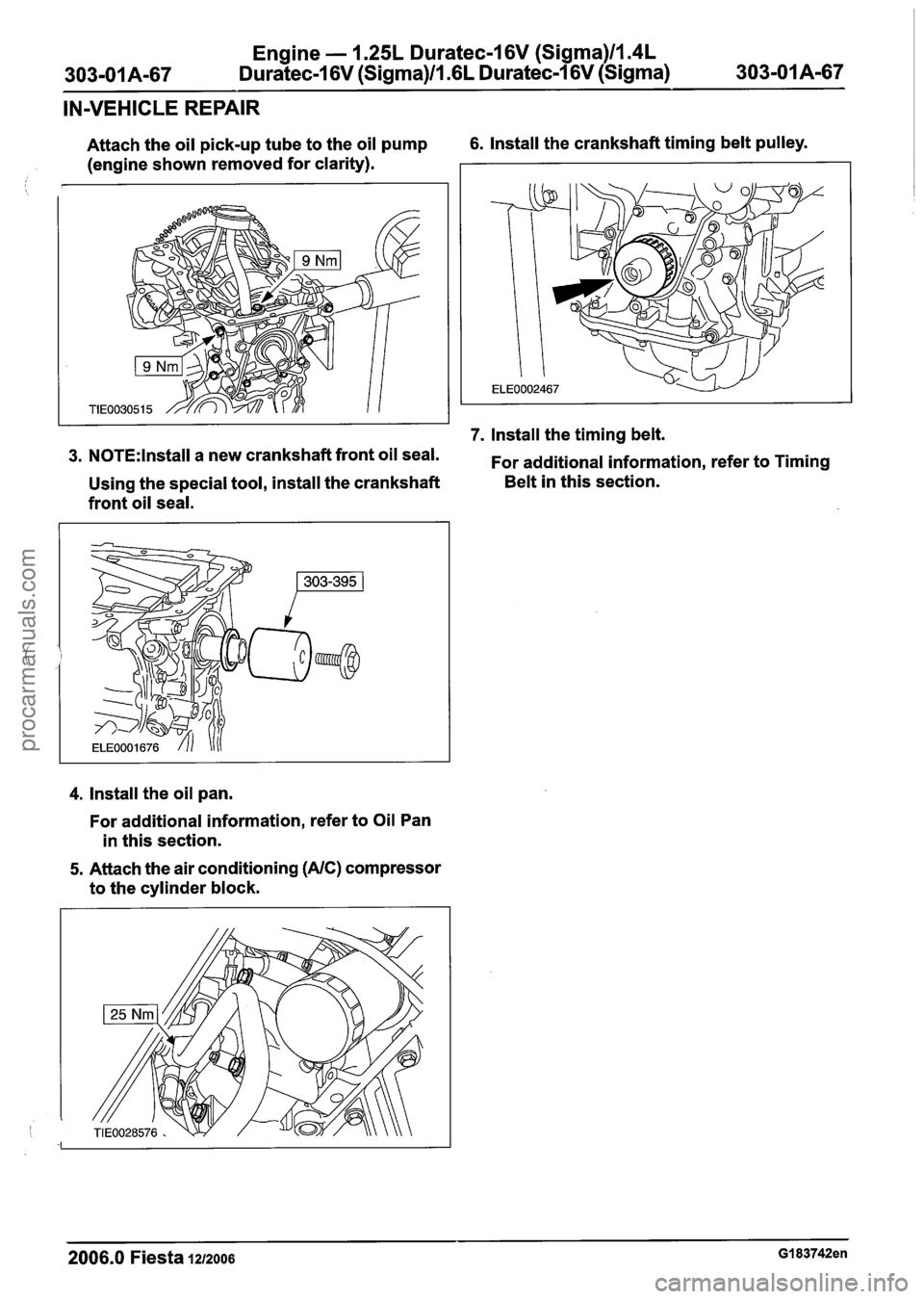
Attach the oil pick-up tube to the oil pump 6. Install the crankshaft timing belt pulley.
(engine shown removed for clarity).
7. Install the timing belt.
3. N0TE:lnstall a new crankshaft front oil seal.
For additional information, refer to Timing
Using the special tool, install the crankshaft Belt
in this section.
front oil seal.
4. Install the oil pan.
For additional information, refer to Oil Pan
in this section.
5. Attach the air conditioning (AIC) compressor
to the cylinder block.
2006.0 Fiesta 1212006 GI 83742en
procarmanuals.com
Page 544 of 1226
Engine - 1.25L Duratec-1 6V (Sigma)ll.4L
303-01 A-68 Duratec-1 6V (Sigma)/l .6L Duratec-1 6V (Sigma) 303-01 A-68
IN-VEHICLE REPAIR
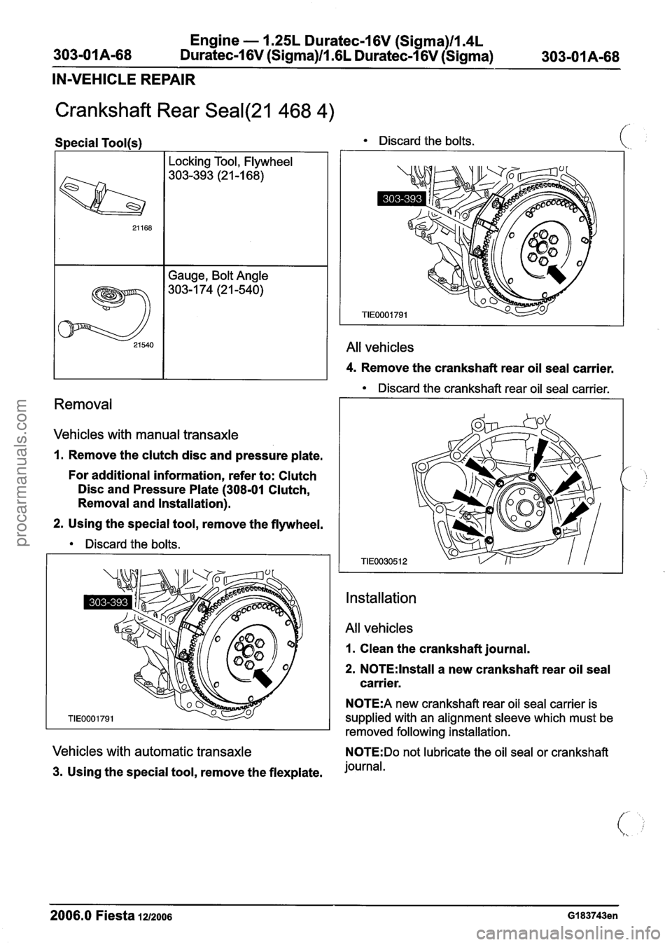
Crankshaft Rear Seal(21 468 4)
Discard the crankshaft rear oil seal carrier.
Removal
Special Tool(s) Discard the bolts.
Vehicles with manual transaxle
21168
21 540
1. Remove the clutch disc and pressure plate.
For additional information, refer to: Clutch
Disc and Pressure Plate (308-01 Clutch,
Removal and lnstallation).
2. Using the special tool, remove the flywheel.
Discard the bolts. Locking
Tool, Flywheel
303-393 (21 -1 68)
Gauge, Bolt Angle
303- 1 74 (2 1 -540)
Installation
All vehicles
4. Remove the crankshaft rear oil seal carrier.
All vehicles
1. Clean the crankshaft journal.
2. N0TE:lnstall a new crankshaft rear oil seal
carrier.
N0TE:A new crankshaft rear oil seal carrier is
supplied with an alignment sleeve which must be
removed following installation.
Vehicles with automatic transaxle N0TE:Do not lubricate the oil seal or crankshaft
3. Using the special tool, remove the flexplate. journal.
2006.0 Fiesta 1212006 GI 83743en
procarmanuals.com
Page 545 of 1226
Engine - 1.25L Duratec-1 6V (Sigma)ll.4L
303-01 A-69 Duratec-1 6V (Sigma)/l .6L Duratec-I 6V
(Sigma)
303-01 A-69
IN-VEHICLE REPAIR
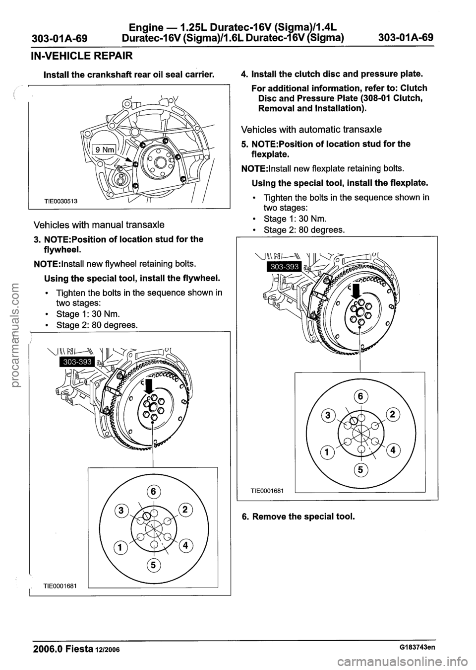
Install the crankshaft rear oil seal carrier. 4. Install the clutch disc and pressure plate.
For additional information, refer to: Clutch
Disc and Pressure Plate (308-01 Clutch,
Removal and Installation).
Vehicles with automatic transaxle
5. N0TE:Position of location stud for the
flexplate.
NOTE:
l nstall new flexplate retaining bolts.
Using the special tool, install the flexplate.
Tighten the bolts in the sequence shown in
two stages:
Vehicles with manual transaxle Stage 1: 30 Nm.
Stage 2: 80 degrees. - 3. N0TE:Position of location stud for the -
flywheel.
N0TE:lnstall new flywheel retaining bolts.
Using the special tool, install the flywheel.
Tighten the bolts in the sequence shown in
two stages:
Stage 1: 30
Nm.
Stage 2: 80 degrees.
1
6. Remove the special tool.
2006.0 Fiesta 1212006 GI 83743en
procarmanuals.com
Page 546 of 1226
Engine - 1.25L Duratec-1 6V (Sigma)ll.4L
303-01 A-70 Duratec-I 6V (Sigma)lll6L Duratec-1 6V (Sigma) 303-01 A-70
REMOVAL
Engine
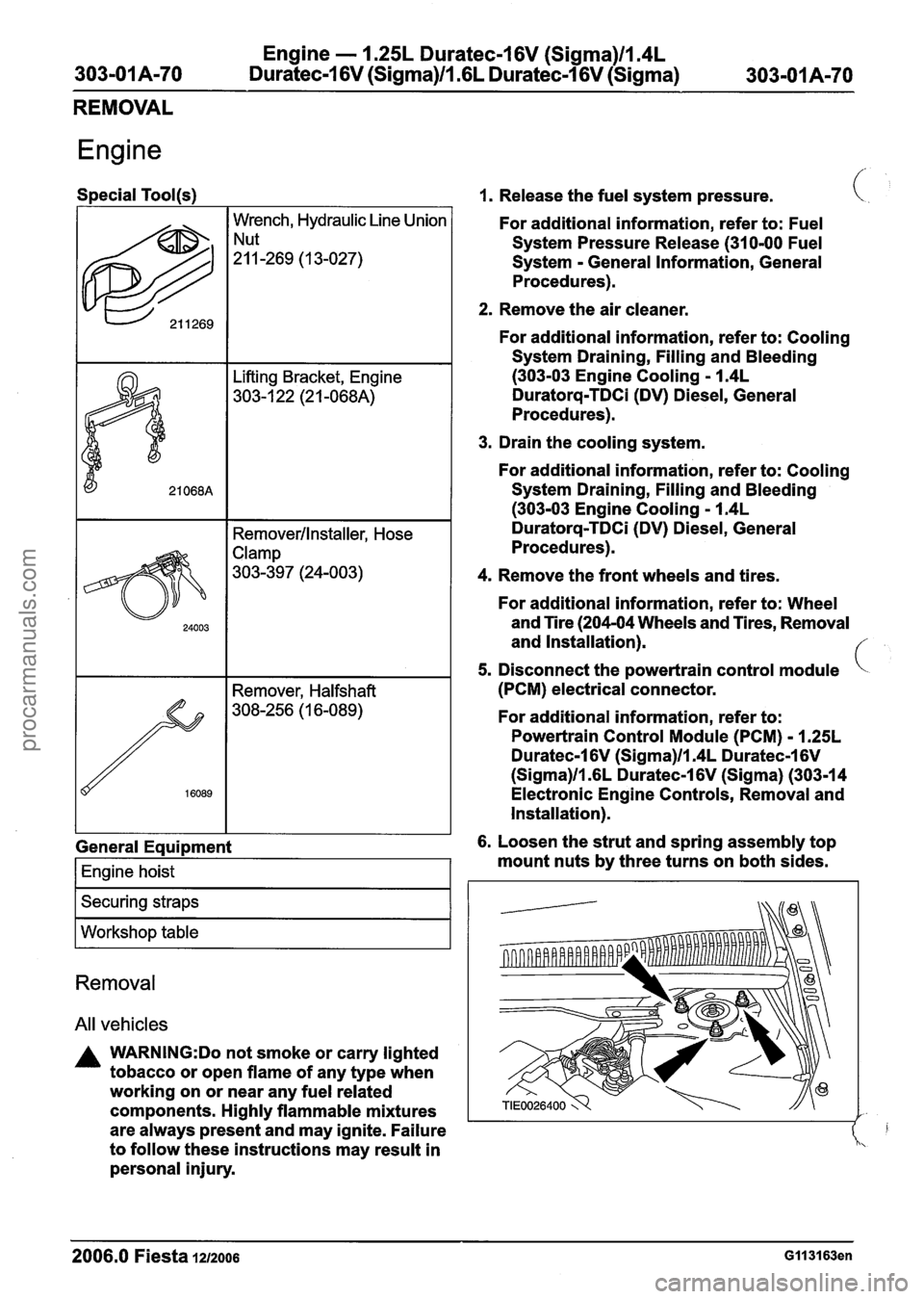
Special Tool(s)
I I Removerllnstaller, Hose
622
General Eaui~ment
Wrench, Hydraulic Line Union
!:!-269 ( 1 3-027)
I Engine hoist I
I Securing straps I
I Workshop table I
Removal
All vehicles
A WARNING:Do not smoke or carry lighted
tobacco or open flame of any type when
working on or near any fuel related
components. Highly flammable mixtures
are always present and may ignite. Failure
to follow these instructions may result in
personal injury.
1. Release the fuel system pressure.
For additional information, refer to: Fuel
System Pressure Release (31 0-00 Fuel
System
- General Information, General
Procedures).
2. Remove the air cleaner.
For additional information, refer to: Cooling
System Draining, Filling and Bleeding
(303-03 Engine Cooling - 1.4L
Duratorq-TDCi (DV) Diesel, General
Procedures).
3. Drain the cooling system.
For additional information, refer to: Cooling
System Draining, Filling and Bleeding
(303-03 Engine Cooling - 1.4L
Duratorq-TDCi (DV) Diesel, General
Procedures).
4. Remove the front wheels and tires.
For additional information, refer to: Wheel
and Tire (204-04 Wheels and Tires, Removal
and Installation).
5. Disconnect the powertrain control module
(PCM) electrical connector.
For additional information, refer to:
Powertrain Control Module (PCM)
- 1.25L
Duratec-1 6V (Sigma)ll.4L Duratec-1 6V
(Sigma)ll .6L Duratec-1 6V (Sigma) (303-1 4
Electronic Engine Controls, Removal and
Installation).
6. Loosen the strut and spring assembly top
mount nuts by three turns on both sides.
2006.0 Fiesta 1212006 GII 31 63en
procarmanuals.com
Page 547 of 1226
Engine - I .25L Duratec-1 6V (Sigma)ll.4L
Duratec-1 6V (Sigma)ll .6L Duratec-1 6V (Sigma)
REMOVAL
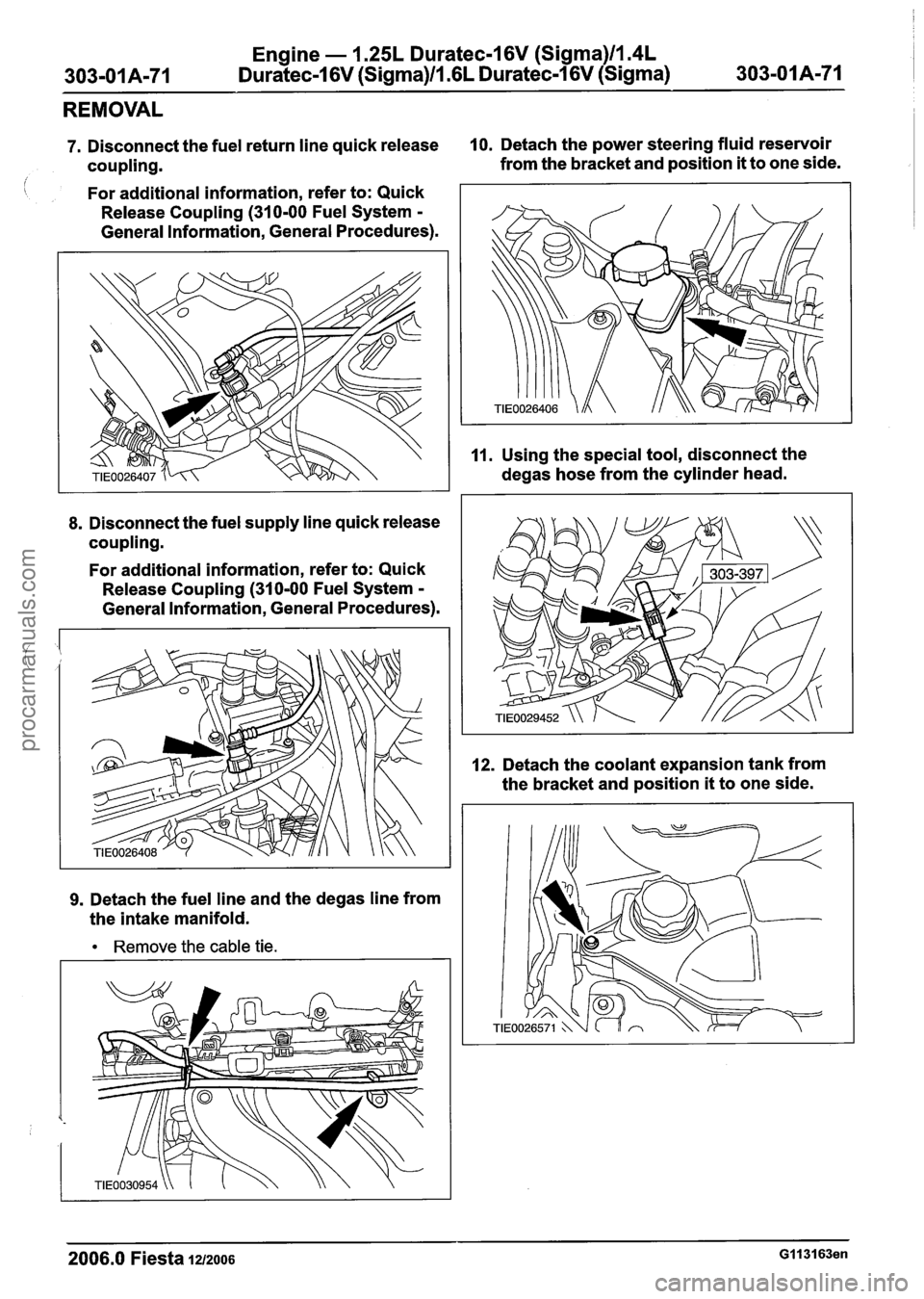
7. Disconnect the fuel return line quick release 10. Detach the power steering fluid reservoir
coupling. from
the bracket and position
it to one side.
i For additional information, refer to: Quick
Release Coupling
(310-00 Fuel System -
General Information, General Procedures).
8. Disconnect the fuel supply line quick release
coupling.
For additional information, refer to: Quick
Release Coupling
(310-00 Fuel System -
General Information, General Procedures).
9. Detach the fuel line and the degas line from
the intake manifold.
Remove the cable tie. 11.
Using
the special tool, disconnect the
degas hose from the cylinder head.
12. Detach the coolant expansion tank from
the bracket and position
it to one side.
2006.0 Fiesta 1212006 GI 131 63en
procarmanuals.com
Page 548 of 1226
Engine - 1.25L Duratec-1 6V (Sigma)ll.4L
303-01 A-72 Duratec-1 6V (Sigma)Il.GL Duratec-1 6V (Sigma) 303=01 A-72
REMOVAL
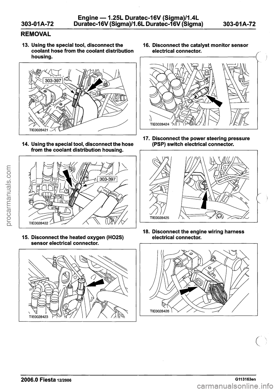
13. Using the special tool, disconnect the 16. Disconnect the catalyst monitor sensor
coolant hose from the coolant distribution electrical connector.
housing.
I
17. Disconnect the power steering pressure
14. Using the special tool, disconnect the hose
(PSP) switch electrical connector.
from the coolant distribution housing.
18. Disconnect the engine wiring harness
15. Disconnect the heated oxygen (H02S) electrical connector.
sensor electrical connector.
2006.0 Fiesta 1212006 Gll3163en
procarmanuals.com