engine FORD FIESTA 2007 Workshop Manual
[x] Cancel search | Manufacturer: FORD, Model Year: 2007, Model line: FIESTA, Model: FORD FIESTA 2007Pages: 1226, PDF Size: 61.26 MB
Page 589 of 1226
Engine - 1.25L Duratec-1 6V (Sigma)ll.4L
303-01A-I13 Duratec-1 6V (Sigma)/l .6L Duratec-1 6V (Sigma)
303-01 A-I 13
ASSEMBLY
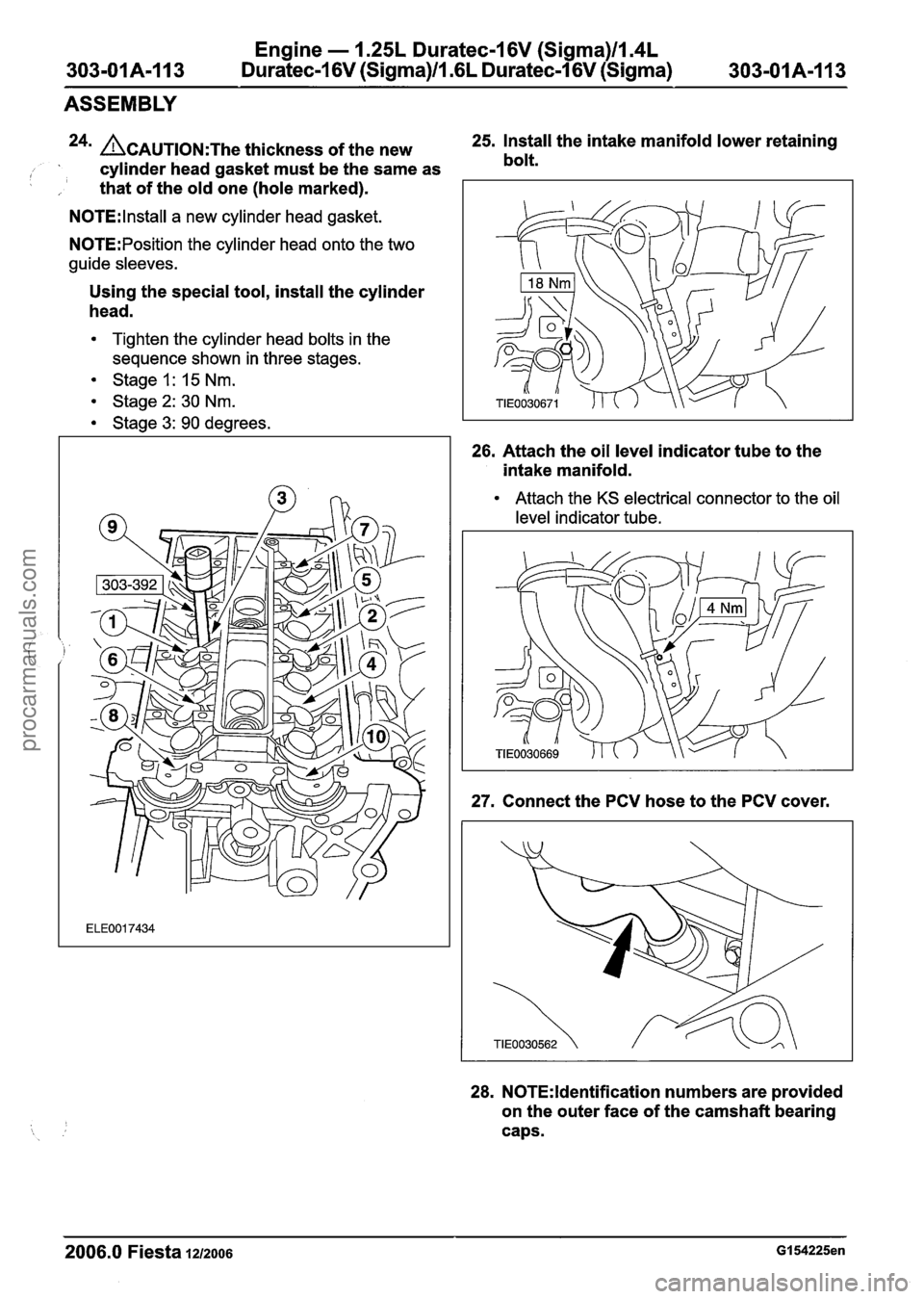
24n ACAUTION:T~~ thickness of the new 25.
Install the intake manifold lower retaining
, cylinder head gasket must be the same as bolt.
I , that
of the old one (hole marked).
N0TE:lnstall a new cylinder head gasket.
N0TE:Position the cylinder head onto the two
guide sleeves.
Using the special tool, install the cylinder
head.
Tighten the cylinder head bolts in the
sequence shown in three stages.
Stage 1: 15 Nm.
Stage2: 30 Nm.
Stage 3: 90 degrees.
26. Attach the oil level indicator tube to the
intake manifold.
Attach the KS electrical connector to the oil
level indicator tube.
27. Connect the PCV hose to the PCV cover.
28. N0TE:ldentification numbers are provided
on the outer face of the camshaft bearing
caps.
2006.0 Fiesta 1212006 GI 54225en
procarmanuals.com
Page 590 of 1226
Engine - 1.25L Duratec-1 6V (Sigma)lIl4L
303-01 A-I 14 Duratec-1 6V (Sigma)ll .6L Duratec-1 6V (Sigma) 303-01 A-1 14
ASSEMBLY
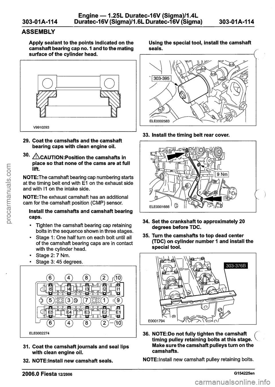
Apply sealant to the points indicated on the
camshaft bearing cap no.
1 and to the mating
surface of the cylinder head.
29. Coat the camshafts and the camshaft
bearing caps with clean engine oil.
30m A~~~~10~:~osition the camshafts in
place so that none of the cams are at full
lift.
N0TE:The camshaft bearing cap numbering starts
at the timing
belt end with El on the exhaust side
and with
I1 on the intake side.
N0TE:The exhaust camshaft has an additional
cam for the camshaft position (CMP) sensor.
Install the camshafts and camshaft bearing
caps.
Tighten the camshaft bearing cap retaining
bolts in the sequence shown in three stages.
Stage 1: One half turn on each bolt until all
of the camshaft bearing caps are in contact
with the
cylinder head.
Stage
2: 7 Nm.
Stage
3: 45 degrees.
31. Coat the camshaft journals and seal lips
with clean engine oil.
32. N0TE:lnstall new camshaft seals. Using the
special tool, install the camshaft
seals.
f:
33. Install the timing belt rear cover.
34. Set the crankshaft to approximately 20
degrees before TDC.
35. Turn the camshafts to top dead center
(TDC) on cylinder number
I and install the
special tool.
36. N0TE:Do not fully tighten the camshaft
timing pulley retaining bolts at this stage.
Make sure the camshaft pulleys turn on the
camshafts.
N0TE:lnstall new camshaft pulley retaining bolts.
2006.0 Fiesta 1u2oos GI 54225en
procarmanuals.com
Page 591 of 1226
Engine - 1.25L Dura
303-01A-115 Duratec-1 6V (Sigma)ll.(
tec-16V (Sigma)ll.4L
iL Duratec-1 6V (Sigma) 303-01A-I15
ASSEMBLY
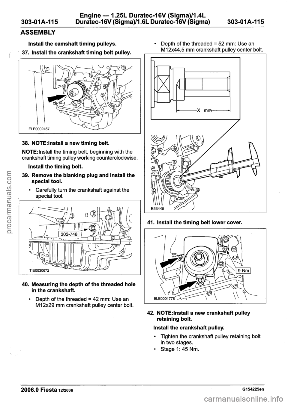
Install the camshaft timing pulleys.
io 37. Install the crankshaft timing belt pulley.
38. N0TE:lnstall a new timing belt.
N0TE:lnstall the timing belt, beginning with the
crankshaft timing pulley working counterclockwise.
Install the timing belt.
39. Remove the blanking plug and install the
special tool.
Carefully turn the crankshaft against the
,I special tool.
40. Measuring the depth of the threaded hole
in the crankshaft.
Depth of the threaded = 42 mm: Use an
MI 2x29 mm crankshaft pulley center bolt. Depth
of the threaded
= 52 mm: Use an
M12x44,5 mm crankshaft pulley center bolt.
41. Install the timing belt lower cover.
42. N0TE:lnstall a new crankshaft pulley
retaining bolt.
Install the crankshaft pulley.
Tighten the crankshaft pulley retaining bolt
in two stages.
Stage 1: 45 Nm.
2006.0 Fiesta 1212006 GI 54225en
procarmanuals.com
Page 592 of 1226
Engine - 1.25L Duratec-1 6V (Sigma)ll.4L
303-01 A-I 16 Duratec-1 6V (Sigma)/l .6L Duratec-1 6V (Sigma)
303-01 A-1 16
ASSEMBLY
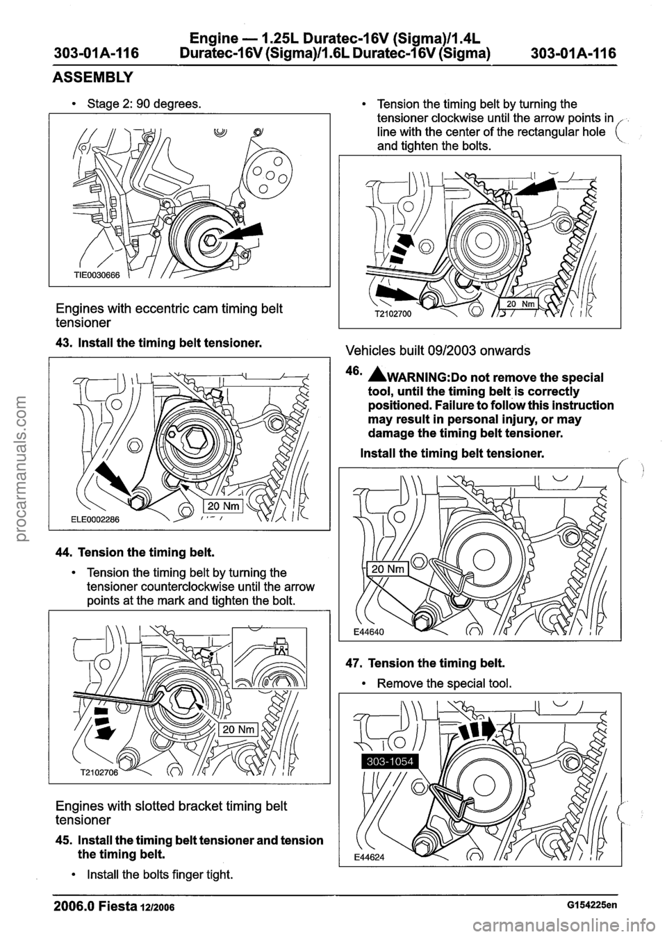
Stage 2: 90 degrees.
Engines with eccentric cam timing belt
tensioner
43. Install the timing belt tensioner.
44. Tension the timing belt.
Tension the timing belt by turning the
tensioner counterclockwise until the arrow
points at the mark and tighten the bolt.
Engines with slotted bracket timing belt
tensioner
45. Install the timing belt tensioner and tension
the timing belt.
Install the bolts finger tight.
Tension the timing belt by turning the
tensioner clockwise until the arrow points in
line with the center of the rectangular hole
(
and tighten the bolts.
Vehicles built 0912003 onwards
46' AWARNING:D~ not remove the special
tool, until the timing belt is correctly
positioned. Failure to follow this instruction
may result in personal injury, or may
damage the timing belt tensioner.
Install the timing belt tensioner.
f,
47. Tension the timing belt.
Remove the special tool.
2006.0 Fiesta 1212006 GI 54225en
procarmanuals.com
Page 593 of 1226
Engine - 1.25L Duratec-1 6V (Sigma)ll.4L
303-01 A-1 17 Duratec-1 6V (Sigma)ll .6L
Duratec-1 6V (Sigma) 303-01 A-1 17
ASSEMBLY
Vehicles built 0412005 onwards Using the special tool, tighten the camshaft
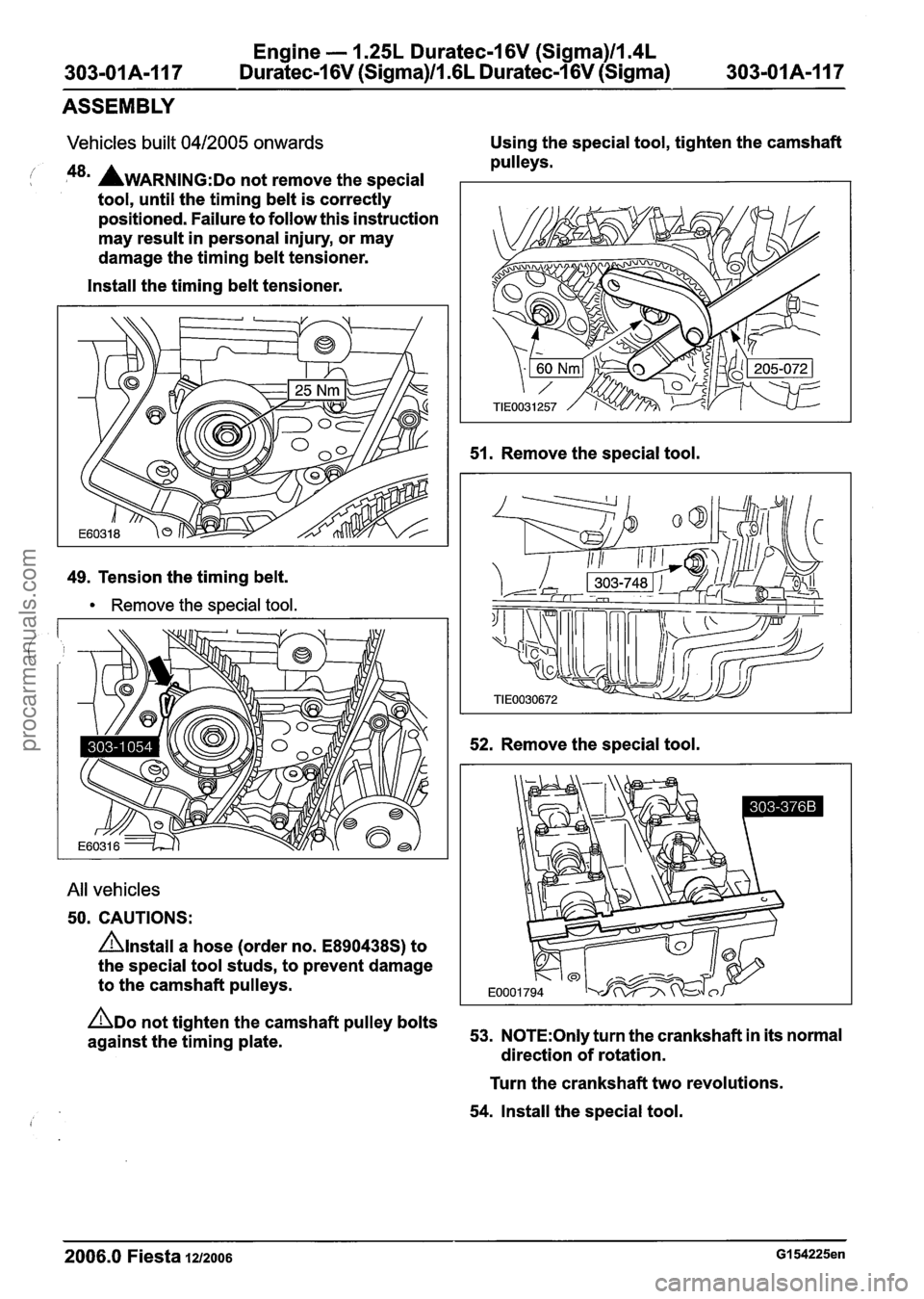
! P8' AWARNING:D~ not remove the special
tool, until the timing belt is correctly
positioned. Failure to follow this instruction
may result in personal injury, or may
damage the timing belt tensioner.
Install the timing belt tensioner.
49. Tension the timing belt.
Remove the special tool.
All vehicles
50. CAUTIONS:
nlnstall a hose (order no. E890438S) to
the special tool studs, to prevent damage
to the camshaft pulleys. pulleys.
51. Remove the special tool.
52. Remove the special tool.
ADO not tighten the camshaft pulley bolts
against the timing plate. 53. N0TE:Only turn
the crankshaft in its normal
direction of rotation.
Turn the crankshaft two revolutions.
54. Install the special tool.
2006.0 Fiesta 1212006 GI 54225en
procarmanuals.com
Page 594 of 1226
Engine - 1.25L Duratec-I 6V (Sigma)ll.4L
303-01 A-1 18 Duratec-1 6V (Sigma)ll .6L Duratec-1 6V (Sigma) 303-01 A-I 18
ASSEMBLY
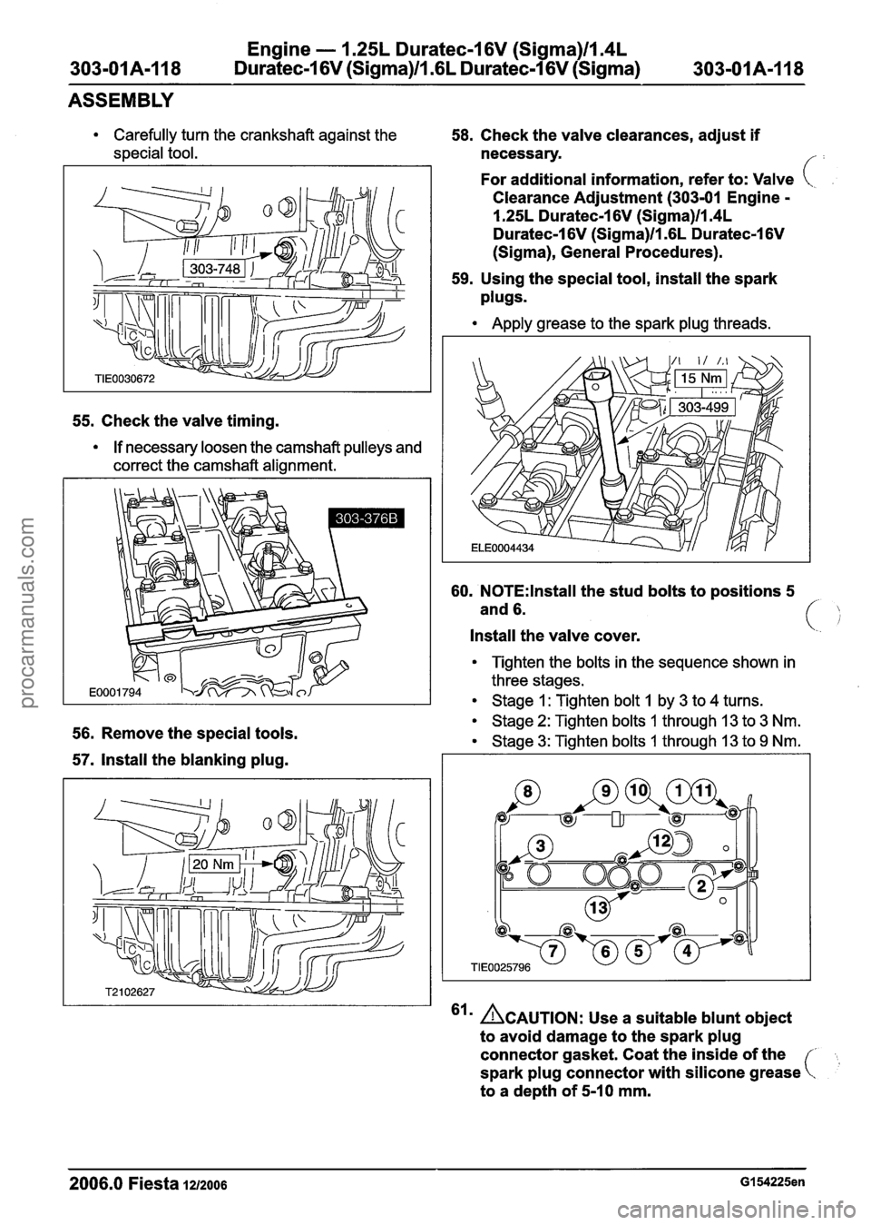
Carefully turn the crankshaft against the
special tool.
55. Check the valve timing.
If necessary loosen the camshaft pulleys and
correct the camshaft alignment.
56. Remove the special tools.
57. Install the blanking plug.
58. Check the valve clearances, adjust if
necessary.
f:
For additional information, refer to: Valve (.
Clearance Adjustment (303-01 Engine -
1.25L Duratec-1 6V (Sigma)ll.4L
Duratec-1 6V (Sigma)ll .6L Duratec-1 6V
(Sigma), General Procedures).
59. Using the
special tool, install the spark
plugs.
Apply grease to the spark plug threads.
60. N0TE:lnstall the stud bolts to positions 5
and 6.
Install the valve cover. (
Tighten the bolts in the sequence shown in
three stages.
Stage I : Tighten bolt 1 by 3 to 4 turns.
Stage
2: Tighten bolts I through 13 to 3 Nm.
Stage
3: Tighten bolts 1 through 13 to 9 Nm.
'Irn CAUTION: Use a suitable blunt object
to avoid damage to the spark
plug
connector gasket. Coat the inside of the
spark
plug connector with silicone grease
to a depth of 5-10 mm. C
2006.0 Fiesta 1212006 GI 54225en
procarmanuals.com
Page 595 of 1226
Engine - 1.25L Duratec-1 6V (Sigma)llm4L
303-OIA-119 Duratec-1 6V (Sigma)llI6L Duratec-1 6V (Sigma) 303-01 A-1 19
ASSEMBLY
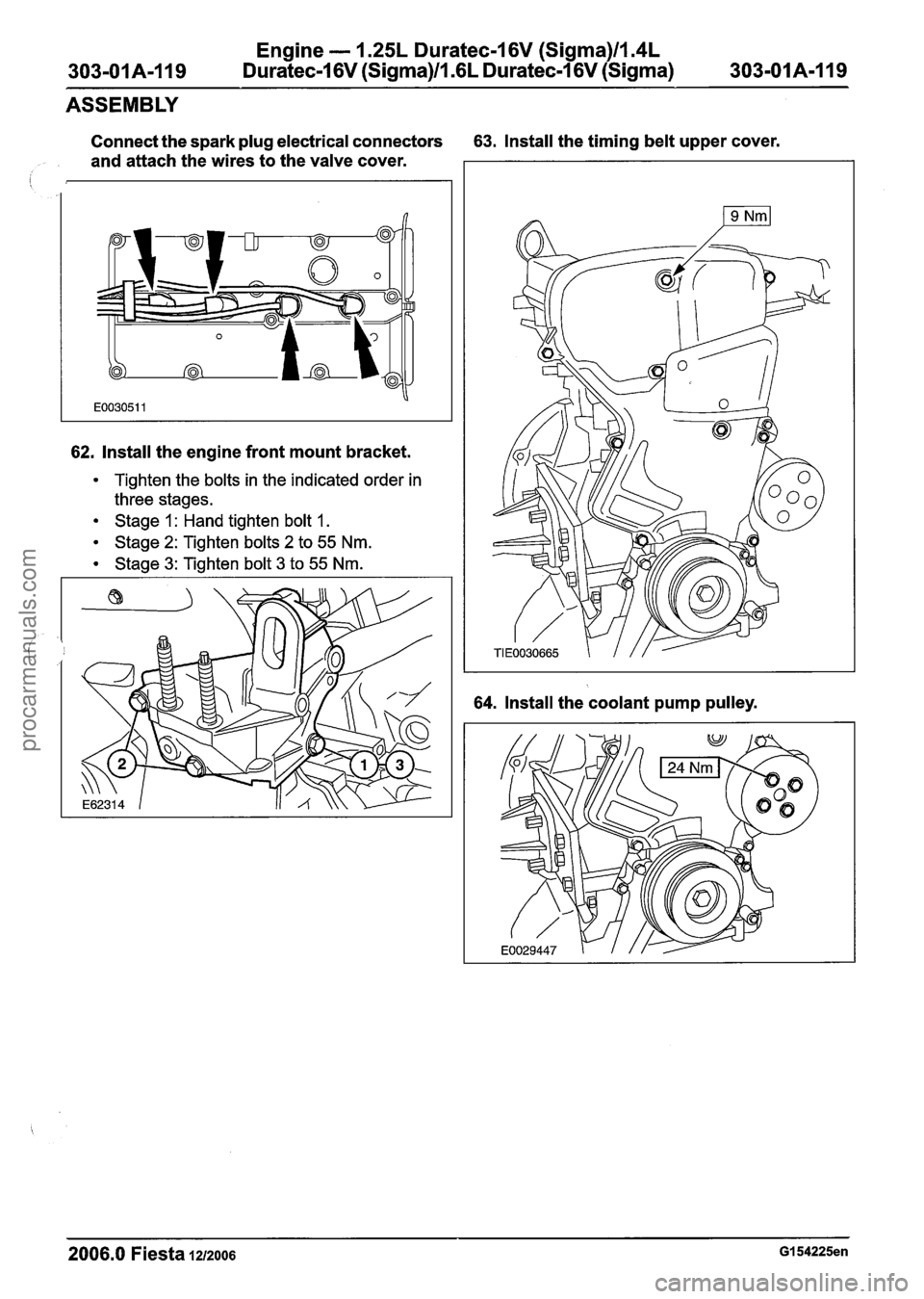
Connect the spark plug electrical connectors 63. Install the timing belt upper cover.
and attach the wires to the valve cover.
I
62. Install the engine front mount bracket.
Tighten the bolts in the indicated order in
three stages.
Stage 1 : Hand tighten bolt 1.
Stage 2: Tighten bolts 2 to 55 Nm.
Stage 3: Tighten bolt 3 to 55 Nm.
64. Install the coolant pump pulley.
2006.0 Fiesta 1~1zoo6 GI 54225en
procarmanuals.com
Page 596 of 1226
Engine - 1.25L Duratec-1 6V (Sigma)llm4L
303-01 A-I 20 Duratec-1 6V (Sigma)/l .6L Duratec-1 6V (Sigma)
303-01 A-I 20
ASSEMBLY
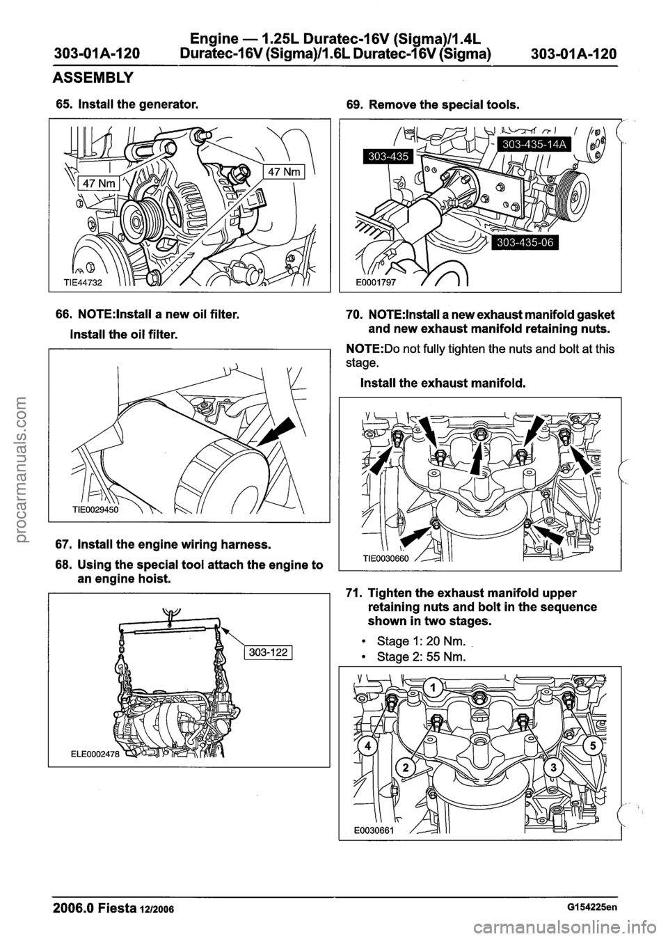
65. Install the generator.
66. N0TE:lnstall a new oil filter.
Install the oil filter.
67. Install the engine wiring harness.
69. Remove the special tools.
70. N0TE:lnstall a new exhaust manifold gasket
and new exhaust manifold retaining nuts.
N0TE:Do not fully tighten the nuts and bolt at this
stage.
Install the exhaust manifold.
68. Using the special tool attach the engine to
an engine hoist.
71. Tighten the exhaust manifold upper
retaining nuts and bolt in the sequence
shown in two stages.
Stage
I: 20 Nm.
Stage 2: 55 Nm.
2006.0 Fiesta 1212006 GI 54225en
procarmanuals.com
Page 597 of 1226
Engine - 1.25L Duratec-1 6V (Sigma)lIa4L
Duratec-1 6V (Sigma)ll .6L Duratec-1 6V (Sigma)
ASSEMBLY
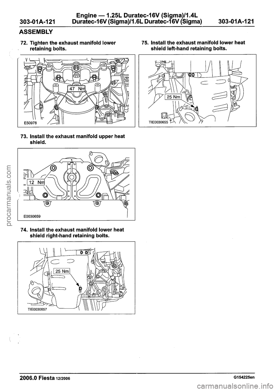
72. Tighten the exhaust manifold lower 75, Install the exhaust manifold lower heat
. retaining bolts. shield left-hand retaining bolts. I
73. Install the exhaust manifold upper heat
shield.
74. Install the exhaust manifold lower heat
shield right-hand retaining bolts.
2006.0 Fiesta 1212006 GI 54225en
procarmanuals.com
Page 598 of 1226
Engine - 1.25L Duratec-1 6V (Sigma)ll.4L
303-01 A-I 22 Duratec-1 6V (Sigma)/l .6L Duratec-1 6V (Sigma)
303-01 A-1 22
INSTALLATION
Engine
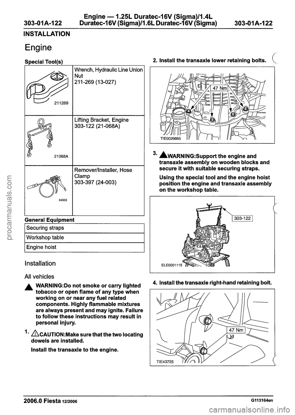
Special Tool(s) 2. Install the transaxle lower retaining bolts. \.,
622
I I Remover/lnstaller, Hose
Wrench,
Hydraulic Line Union
"-269 (I 3-027)
- --
21 068A
Clamp
303-397 (24-003)
ift tins racket, Engine
303-1 22 (2 1 -068A)
General Equipment
I Securing straps I
I Workshop table I
I Engine hoist I
Installation
All vehicles
A WARN1NG:Do not smoke or carry lighted
tobacco or open flame of any type when
working on or near any fuel related
components. Highly flammable mixtures
are always present and may ignite. Failure
to follow these instructions may result in
personal injury.
I' ACAUTION:M~~~ sure that the two locating
dowels are installed.
Install the transaxle to the engine.
3m AWARNING:S~~~~~~ the engine and
transaxle assembly on wooden blocks and
secure
it with suitable securing straps.
Using the special tool and the engine hoist
position the engine and transaxle assembly
on the workshop table.
4. lnstall the transaxle right-hand retaining bolt.
2006.0 Fiesta 1212006 GII 3164en
procarmanuals.com