engine FORD FIESTA 2007 Workshop Manual
[x] Cancel search | Manufacturer: FORD, Model Year: 2007, Model line: FIESTA, Model: FORD FIESTA 2007Pages: 1226, PDF Size: 61.26 MB
Page 619 of 1226
Engine - 1.25L Duratec-1 6V (Sigma)ll.4L
303-01 A-1 43 Duratec-1 6V (Sigma)/l.GL Duratec-1 6V (Sigma) 303-01 A-I
43
INSTALLATION
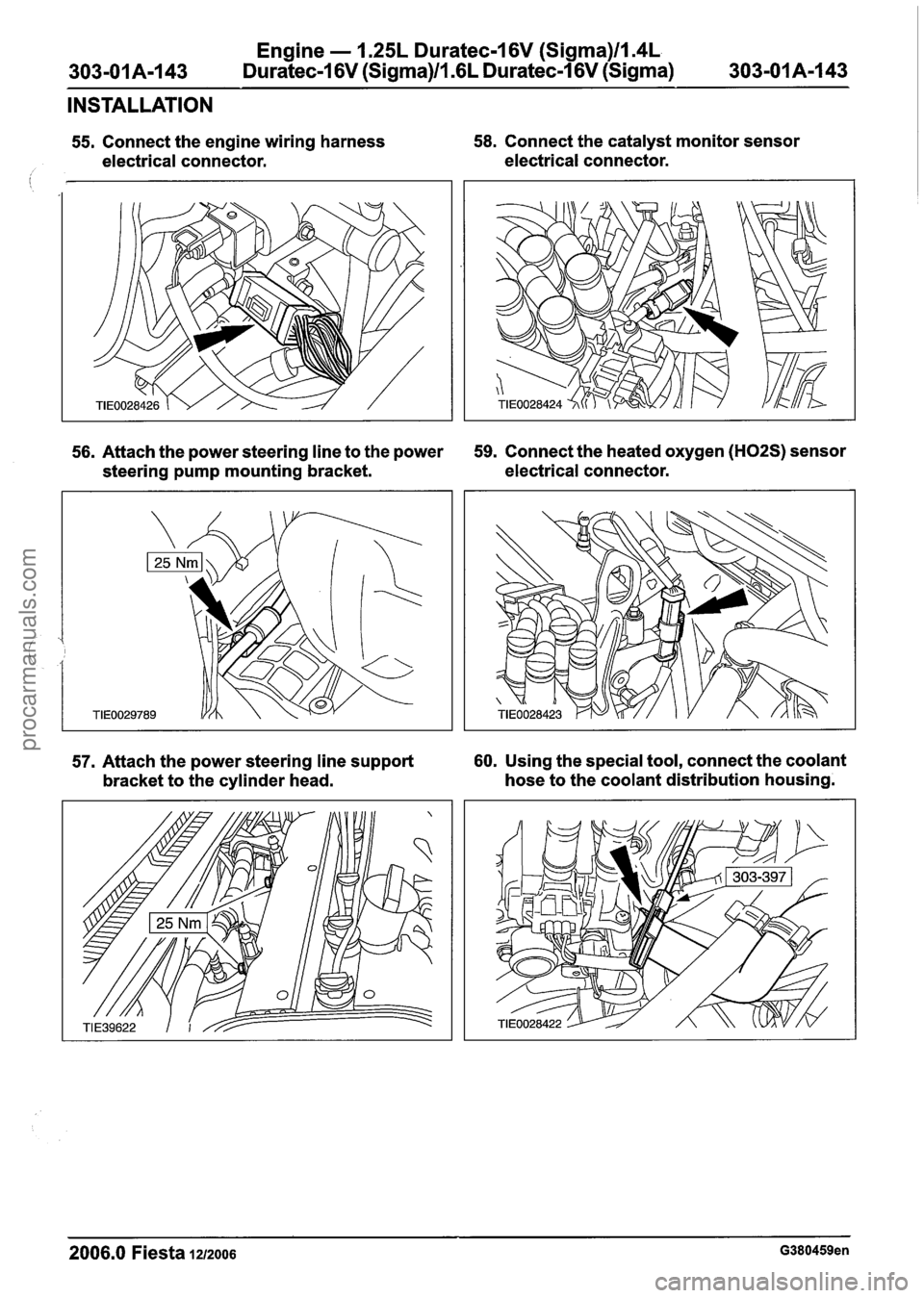
55. Connect the engine wiring harness 58. Connect the catalyst monitor sensor
electrical connector. electrical connector.
i
56. Attach the power steering line to the power 59. Connect the heated oxygen (H02S) sensor
steering pump mounting bracket. electrical
connector.
57. Attach the power steering line support 60. Using the special tool, connect the coolant
bracket to the cylinder head. hose
to the coolant distribution housing.
2006.0 Fiesta 1212006 G380459en
procarmanuals.com
Page 620 of 1226
Engine - 1.25L Duratec-1 6V (Sigma)ll.4L
303-01 A-I 44 Duratec-I 6V (Sigma)ll .6L Duratec-1 6V (Sigma) 303-01 A-1 44
INSTALLATION
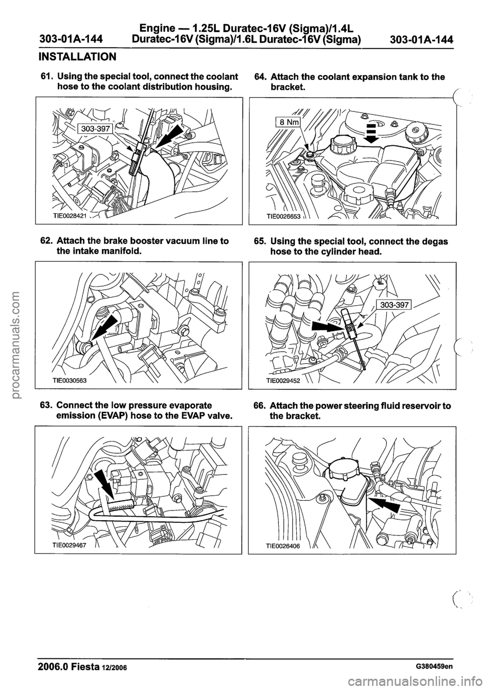
61. Using the special tool, connect the coolant
hose to the coolant distribution housing. 64. Attach the coolant expansion tank to the
bracket.
/
62. Attach the brake booster vacuum line to 65. Using the special tool, connect the degas
the intake manifold.
hose to the cylinder head.
63. Connect the low pressure evaporate 66. Attach the power steering fluid reservoir to
emission (EVAP) hose to the EVAP valve.
the bracket.
2006.0 Fiesta 12/2006 G380459en
procarmanuals.com
Page 621 of 1226
Engine - 1.25L Duratec-1 6V (Sigma)ll.4L
303-01 A-1 45 Duratec-1 6V (Sigma)ll .6L
Duratec-1 6V (Sigma) 303-01 A-1 45
INSTALLATION
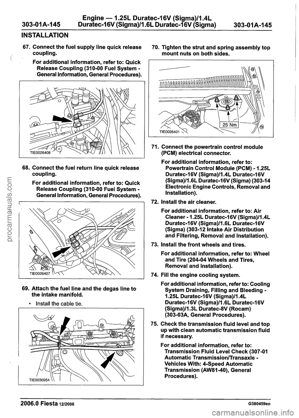
67. Connect the fuel supply line quick release
70. Tighten the strut and spring assembly top
coupling. mount nuts on both sides.
(: , For additional information, refer to: Quick
Release Coupling (310-00 Fuel System
-
General Information, General Procedures).
68. Connect the fuel return line quick release
coupling.
For additional information, refer to: Quick
Release Coupling (310-00 Fuel System
-
General Information, General Procedures).
69. Attach the fuel line and the degas line to
the intake manifold.
Install the cable tie.
71. Connect the powertrain control module
(PCM) electrical connector.
For additional information, refer to:
Powertrain Control Module (PCM)
- 1.25L
Duratec-1 6V (Sigma)llm4L Duratec-1 6V
(Sigma)ll.GL Duratec-1 6V (Sigma) (303-14
Electronic Engine Controls, Removal and
Installation).
72, Install the air cleaner.
For additional information, refer to: Air
Cleaner
- 1.25L Duratec-1 6V (Sigma)ll.4L
Duratec-1 6V (Sigma)ll.GL Duratec-1 6V
(Sigma) (303-1 2 Intake Air Distribution
and Filtering, Removal and Installation).
73. Install the front wheels and tires.
For additional information, refer to: Wheel
and Tire (204-04 Wheels and Tires,
Removal and lnstallation).
74. Fill the engine cooling system.
For additional information, refer to: Cooling
System Draining, Filling and Bleeding
-
1.25L Duratec-1 6V (Sigma)ll.4L
Duratec-1 6V (Sigma)ll .6L Duratec-1 6V
(Sigma)ll.3L DuratecdV (Rocam)
(303-03A, General Procedures).
75. Check the transmission fluid level and top
up with clean automatic transmission fluid
if necessary.
For additional information, refer to:
Transmission Fluid Level Check (307-01
Automatic
Transmission/Transaxle -
Vehicles With: 4-Speed Automatic
Transmission
(AW81-40), General
Procedures).
--
2006.0 Fiesta 1212006 G380459en
procarmanuals.com
Page 623 of 1226
303-01 B-I Engine -- 2.OL Duratec-HE (M14) 303-01 B-1
SECTION 303-01 B Engine . 2.OL Duratec-HE (M14)
VEHICLE APPLICATION:2006.0 Fiesta
CONTENTS
SPECIFICATIONS
........................................................................\
.............................................. Specifications
Engine Data
........................................................................\
............................................
Engine Oil ........................................................................\
...............................................
........................................................................\
............................................... Oil system
Engine Oil Capacity
........................................................................\
................................
Valve Dimensions ........................................................................\
...................................
Camshaft Dimensions ........................................................................\
.............................
Crankshaft Dimensions ........................................................................\
...........................
Piston Dimensions ........................................................................\
..................................
Cylinder Head ........................................................................\
.........................................
Cylinder Block ........................................................................\
.........................................
PAGE
DESCRIPTION AND OPERATION
Engine ........................................................................\
......................................................... 303-01 8-8
DIAGNOSIS AND TESTING
Engine ........................................................................\
.........................................................
GENERAL PROCEDURES
........................................................................\
....................... Valve Clearance Adjustment
IN-VEHICLE REPAIR
Intake Manifold ........................................................................\
................. (21 183 0)
Crankshaft Front Seal ........................................................................\
............. (21 467 0)
Crankshaft Pulley ........................................................................\
................... (21 5720)
Valve Seals ........................................................................\
....................... (21 238 0)
Valves ........................................................................\
................................. (21 2154)
Camshafts ........................................................................\
.......................... (21 284 0)
Oil Pan ........................................................................\
................................. (21 154 0)
Oil Pump ........................................................................\
.............................. (21 714 0)
Crankshaft Rear Seal ........................................................................\
.......... (21 468 4)
Engine Front Cover ........................................................................\
............. (21 148 0)
Exhaust Manifold ........................................................................\
........................................
Timing Chain ........................................................................\
........................ (21 314 0)
Cylinder Head ........................................................................\
....................... (21 163 0)
REMOVAL
Engine ........................................................................\
.........................................................
DISASSEMBLY
Engine ........................................................................\
................................ (21 134 8)
procarmanuals.com
Page 624 of 1226
303-01 B-2 Engine - 2.OL Duratec-HE (M14) 303-01 B-2
ASSEMBLY
(' Engine ........................................................................\
................................ (21 1348) 303-018-,.
INSTALLATION
Engine ........................................................................\
......................................................... 303-01 B-I 1 I
procarmanuals.com
Page 625 of 1226
Engine - 2.OL Duratec-HE (M14)
SPECIFICATIONS
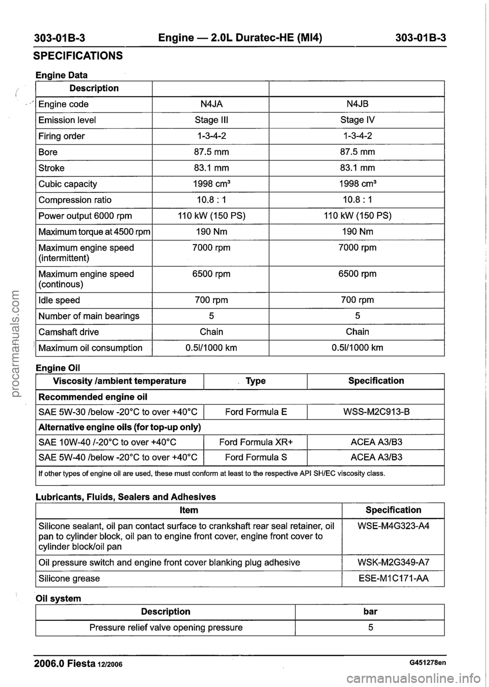
Engine Data
Description
I Engine code I N4JA I N4JB I
IEmission level I Stage III I Stage IV I
I Firing order I 1 -3-4-2 I 1 -3-4-2 I
1 Bore I 87.5 mm I 87.5 mm I
1 Stroke I 83.1 mm I 83.1 mm I
I Power output 6000 rpm 1 110 kW (150 PS) I 110 kW (1 50 PS) I
Cubic capacity
Compression ratio
I Maximum torque at 4500 rpm I 190 Nm I 190 Nm I
Maximum engine speed
(intermittent) 1998
cm3
10.8
: I
7000 rprn 1998
cm3
10.8
: 1
7000 rprn
Maximum engine speed
(continous) 6500
rprn 6500 rprn
I Idle speed I 700 rpm I 700 rpm I
I Number of main bearings I 5 I 5 I
!
Engine Oil
I SAE 1 OW-40 I-20°C to over +40°C I Ford Formula XR+ I ACEA A3lB3 I
Camshaft drive
Maximum oil consumption
Viscosity
/ambient temperature
Recommended engine oil
~40%%0w -20°C to over +40°C I Ford Formula S I ACEA A3lB3 I
SAE 5W-30 /below -20°C to over +40°C
I If other types of engine oil are used, these must conform at least to the respective API SHlEC viscosity class.
Chain
0.5111 000 km
- Type
Lubricants, Fluids, Sealers and Adhesives Chain
0.5111 000 km
Specification
Alternative engine oils (for top-up only) Ford Formula
E
I Item I Specification I
WSS-M2C913-B
I Oil pressure switch and engine front cover blanking plug adhesive I WSK-M2G349-A7 I
Silicone sealant, oil pan contact surface to crankshaft rear seal retainer, oil
pan to
cylinder block, oil pan to engine front cover, engine front cover to
cylinder blockloil pan
ISilicohe grease I ESE-MlC171-AA I
WSE-M4G323-A4
' Oil svstem
I Description I bar I
2006.0 Fiesta 1212006 G451278en
- -
Pressure relief valve opening pressure 5
procarmanuals.com
Page 626 of 1226
Engine - 2.OL Duratec-HE (M14)
SPECIFICATIONS
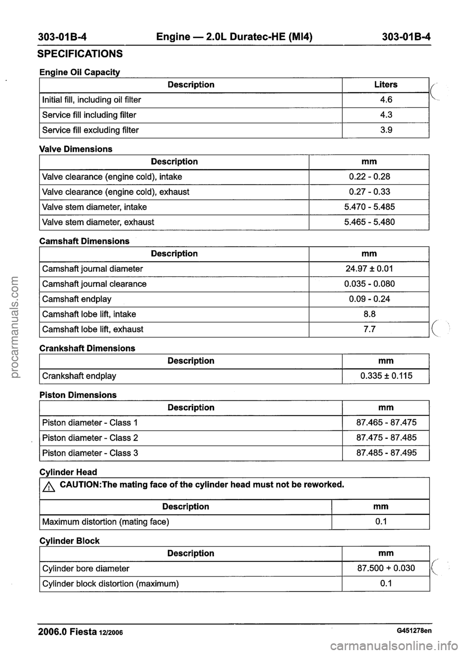
I Service fill including filter I 4.3 I
Engine Oil Capacity
I Service fill excluding filter I 3.9 I
Description
Initial fill, including oil filter
Valve Dimensions Liters
4.6
Camshaft Dimensions Description
Valve
clearance (engine cold), intake
Valve clearance (engine cold), exhaust
Valve stem diameter, intake
Valve stem diameter, exhaust
mm
0.22 - 0.28
0.27
- 0.33
5.470
- 5.485
5.465
- 5.480
I Camshaft journal clearance I 0.035 - 0.080 I
Description
Camshaft journal diameter
I Camshaft endplay I 0.09 - 0.24 I
mm
24.97 + 0.01
Camshaft lobe lift, intake
Camshaft lobe lift, exhaust
Piston Dimensions
8.8
7.7
Description
Crankshaft endplay
Crankshaft Dimensions
mm
0.335 + 0.1 15
Cvlinder Head Description
Piston diameter - Class 1
Piston diameter - Class 2
Piston diameter - Class 3
1 a CAUTI0N:The mating face
of the cylinder head must not be reworked. mm
87.465 - 87.475
87.475
- 87.485
87.485
- 87.495
I Description I mm I
I Maximum distortion (mating face) I 0.1 I
2006.0 Fiesta 1u2006
Cylinder Block
'(, ',
Description
Cylinder bore diameter
Cylinder block distortion (maximum)
mm
87.500 + 0.030
0.
I
procarmanuals.com
Page 627 of 1226
303-01 B-5 Engine - 2.OL Duratec-HE (M14) 303-01 B-5
SPECIFICATIONS
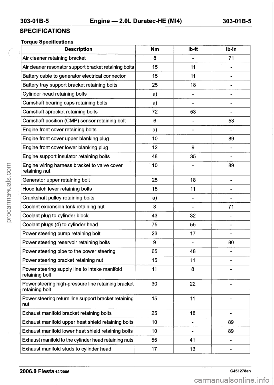
Torque Specifications - --- -- - -- -
Description Nm l b-ft Ib-in
Air cleaner retaining bracket
Air cleaner resonator support bracket retaining bolts Battery cable to generator electrical connector
I Cylinder head retaining bolts I a) I - I - I
Battery tray support bracket retaining bolts
I
--
I Camshaft bearing caps retaining bolts a) IT
15
15
I Camshaft sprocket retaining bolts I 72 I 53 I - I
25
I Camshaft position (CMP) sensor retaining bolt I 6 1 - I 53 I
11
I1
-
-
18
I Engine front cover lower blanking plug I 12 I 9 I - I
-
Engine front cover retaining bolts
Engine front cover upper blanking plug
I Engine support insulator retaining bolts I 48 I 35 I - I
Engine wiring harness bracket to valve cover
retaining nut
a)
10
I Generator upper retaining bolt I 25 I 18 I - I
-
-
I Coolant plugs (4) to cylinder head I 75 I 55 I - I
-
89
Hood latch lever retaining bolts
Crankshaft pulley retaining bolts
Coolant expansion tank retaining nut
Coolant plug to cylinder block
I Power steering pump retaining bolt I 23 I 17 I - I
15
a)
8
43
I
--
I Power steering bracket retaining nut 15 IT
Power steering reservoir retaining bolts
Power steering pipe to the power steering
Power steering supply line to intake manifold
retaining bolt
11
-
-
32
Power steering high-pressure line retaining bracket
retaining bolt
-
-
71
-
9
65
I Power steering return line support bracket retaining I 15 I 11 I - I
1 nut
-
48 80 -
Exhaust
manifold bracket retaining bolts
2006.0 Fiesta 1212006 G451278en
Exhaust manifold upper heat shield retaining bolts
Exhaust manifold lower heat shield retaining bolts
Exhaust manifold to the cylinder head retaining nuts
Exhaust manifold studs to cylinder head
25
10
10
55
17 18
-
-
-
41
13 89
89 -
-
procarmanuals.com
Page 628 of 1226
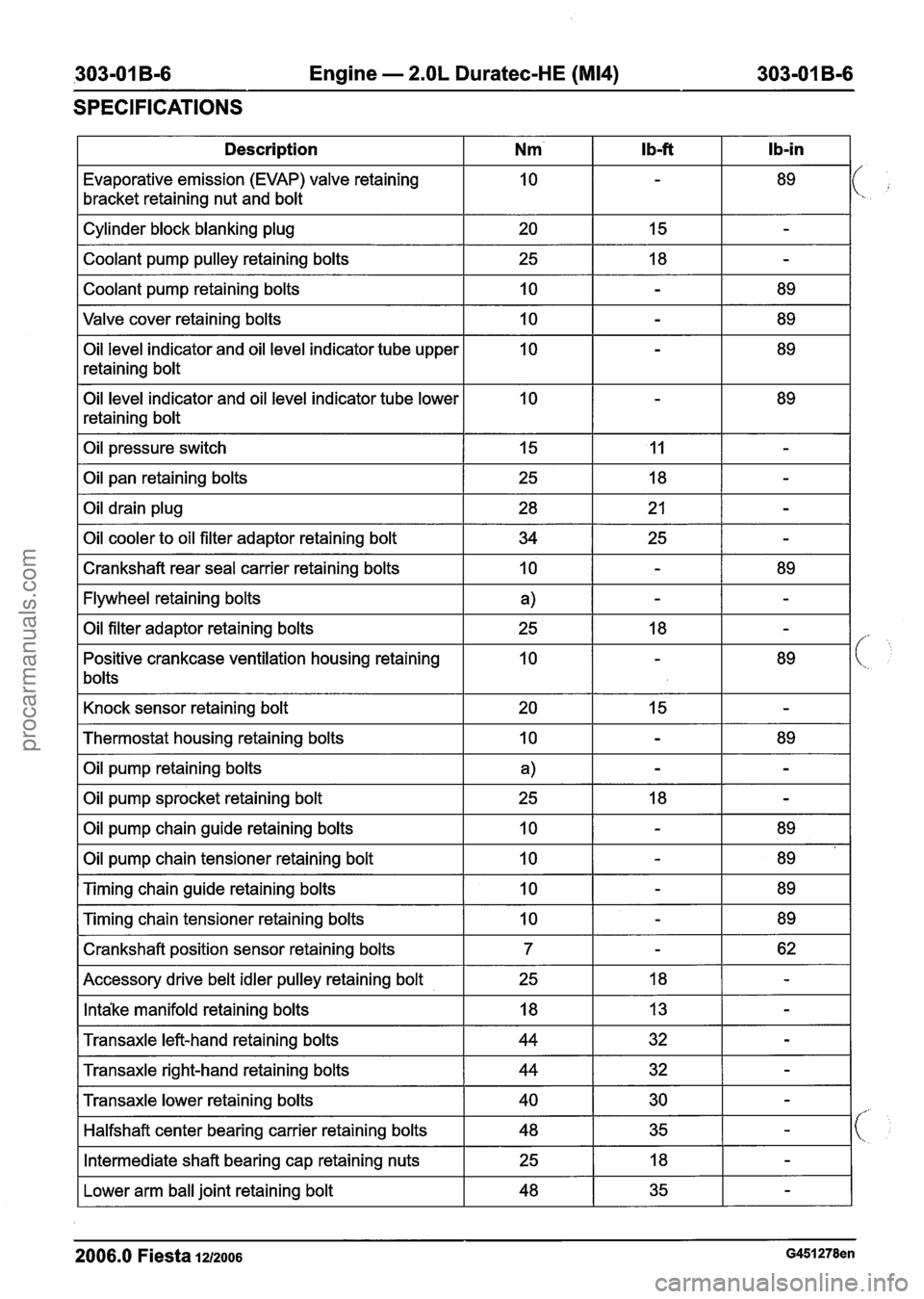
,303-01 B-6 Engine - 2.OL Duratec-HE (M14) 303-01 B-6
SPECIFICATIONS
I Description I Nm' I Ib-ft I Ib-in I
Evaporative emission (EVAP) valve retaining
bracket retaining nut and bolt
Valve cover retaining bolts
I 10 I - I 89 I
Cylinder block blanking plug
Coolant pump pulley retaining bolts
Coolant pump retaining bolts
Oil level indicator and oil level indicator tube upper
retaining bolt
Oil level indicator and oil level indicator tube lower
retaining bolt 20
25
10
Oil pressure switch I 15 I 11 I - I
I Oil pan retaining bolts
15
18
-
-
-
89
I Crankshaft rear seal carrier retaining bolts I 10 I - I 89 I
Oil drain plug
Oil cooler to oil filter adaptor retaining bolt
I Flywheel retaining bolts I a) I - I - I
28
34
I Knock sensor retaining bolt I 20 I 15 I - I
Oil filter adaptor retaining bolts
Positive crankcase ventilation housing retaining
bolts
I Thermostat housing retaining bolts I 10 I - I 89 I
21
25
I Oil pump retaining bolts I a) I - I - I
-
-
25
10
I Oil pump sprocket retaining bolt I 25 I 18 I - I
18
-
-
89
Oil pump chain guide retaining bolts
Oil pump chain tensioner retaining bolt
I Crankshaft position sensor retaining bolts I 7 I - I 62 I
Timing chain guide retaining bolts
Timing chain tensioner retaining bolts
I Accessory drive belt idler pulley retaining bolt I 25 I 18 I - I
10
10
I Intake manifold retaining bolts I 18 I 13 I - I
10
10
I Transaxle left-hand retaining bolts I 44 I 32 I - I
-
-
I Transaxle right-hand retaining bolts I 44 I 32 I - I
89
89
-
-
89
89
Transaxle lower retaining bolts
Halfshaft center bearing carrier retaining bolts
I Lower arm ball joint retaining bolt I 48 I 35 I - I
Intermediate shaft bearing cap retaining nuts
2006.0 Fiesta 1212006 G451278en
40
48
25 30
35 -
-
18 -
procarmanuals.com
Page 629 of 1226
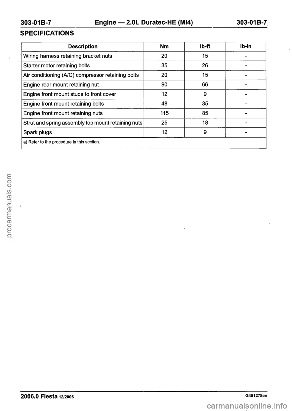
303-01 B-7 Engine - 2.OL Duratec-HE (M14) 303-01 B-7,
SPECIFICATIONS
2006.0 Fiesta 1212006 G451278en
Description
Wiring harness retaining bracket nuts
Starter motor retaining bolts
Air conditioning
(AIC) compressor retaining bolts
Engine rear mount retaining nut
Engine front mount studs to front cover
Engine front mount retaining bolts
Engine front mount retaining nuts
Strut and spring assembly top mount retaining nuts
Spark plugs
a) Refer to the procedure in this section.
Nm
20
35
20 90 12
48
11 5
25 12
I b-fi
15
26 15
66 9
35
85 18 9
Ib-in
-
-
-
-
-
-
-
-
-
procarmanuals.com