Fuel line FORD FIESTA 2007 Service Manual
[x] Cancel search | Manufacturer: FORD, Model Year: 2007, Model line: FIESTA, Model: FORD FIESTA 2007Pages: 1226, PDF Size: 61.26 MB
Page 829 of 1226

Fuel Charging and Controls - 2.OL
303-04B-21 Duratec-HE (M14) 303-04B-21
DIAGNOSIS AND TESTING
Symptom
Engine knock at idle
Possible Sources Action
Fuel injectors.
INSPECT the fuel injectors.
CLEAN the fuel injectors or
INSTALL a new set of injectors
as required only after the
checks have been carried out.
Fuel rail fuel pressure sensor.
Carry out a full engine
diagnosis using the guided
diagnostic menu in WDS.
Low cylinder compression.
CHECK the engine compres-
sion.
Worn or damaged
valve(s),
tappet(s) or camshaft(s).
REMOVE the cylinder head.
INSPECT the cylinder head,
valves, tappets and camshafts
for signs of wear or damage.
REFER to: Cylinder Head (303-
01 C, In-vehicle Repair).
Damaged cylinder head gasket. REMOVE the cylinder head.
INSPECT the cylinder head
gasket and cylinder bores for
wear or damage.
REFER to: Cylinder Head (303-
01 C, In-vehicle Repair).
Low engine oil level.
CHECK the engine oil level.
REFILL as necessary.
Incorrect or contaminated fuel.
-
KS. CHECK
for signs of contamina-
tion such as strange odors from
the fuel tank.
If contaminated fuel is found,
DRAIN the complete fuel
system. FLUSH the fuel system
through with clean gasoline.
REFER to: Fuel Tank Draining
(31
0-OOA, General Proced-
u res).
INSTALL a new fuel filter.
INSPECT the fuel injectors.
CLEAN the fuel injectors or
INSTALL a new set of injectors
as required only after the
checks have been carried out. INSTALL a new fuel rail.
REFER to: Fuel Injection
Supply Manifold
(303-04C,
Removal and Installation).
Carry out a full engine
diagnosis using the guided
diagnostic menu in WDS.
2006.0 Fiesta 1212006 GI 65371 en
procarmanuals.com
Page 837 of 1226
Fuel Charging and Controls - 2.OL
303-04B-29 Duratec-HE (M14) 303-04B-29
REMOVAL AND INSTALLATION
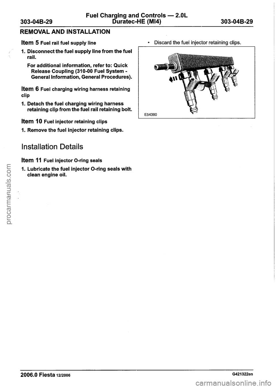
Item 5 Fuel rail fuel supply line
, 1. Disconnect the fuel supply line from the fuel rail.
For additional information, refer to: Quick
Release Coupling (310-00 Fuel System
-
General Information, General Procedures).
Item 6 Fuel charging wiring harness retaining
clip
1. Detach the fuel charging wiring harness
retaining clip from the fuel rail retaining bolt.
Item 10 Fuel injector retaining clips
1. Remove the fuel injector retaining clips.
Installation Details
item 11 Fuel injector O-ring seals
1. Lubricate the fuel injector O-ring seals with
clean engine oil.
Discard the fuel injector retaining clips.
- --
2006.0 Fiesta 1212006 G421322en
procarmanuals.com
Page 923 of 1226
303-1 3-5 Evaporative Emissions 303-1 3-5
REMOVAL
AND INSTALLATION
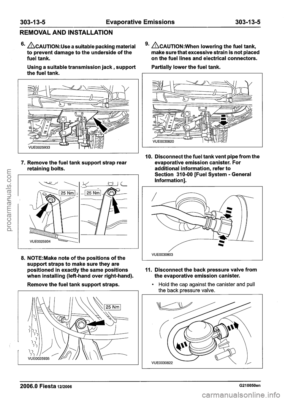
ACAUTION:U~~ a suitable packing material 9m ACAUTION:W~~~ lowering the fuel tank,
to prevent damage to the underside of the make
sure that excessive strain is not placed
fuel tank. on
the fuel lines and electrical connectors.
Using a suitable transmission jack, support Partially lower
the fuel tank.
the fuel tank.
10. Disconnect the fuel tank vent pipe from the
7. Remove the fuel tank support strap rear evaporative
emission canister. For
retaining bolts. additional information,
refer to
Section 31 0-00 [Fuel System
- General
Information].
8. N0TE:Make note of the positions of the
support straps to make sure they are
positioned in exactly the same positions
11. Disconnect the back pressure valve from
when installing (left-hand over right-hand). the
evaporative emission canister.
Remove the fuel tank support straps.
Hold the cap against the canister and pull
the back pressure valve.
2006.0 Fiesta 1212006 G210050en
procarmanuals.com
Page 924 of 1226
303-1 3-6 Evaporative Emissions 303-1 3-6
REMOVAL AND INSTALLATION
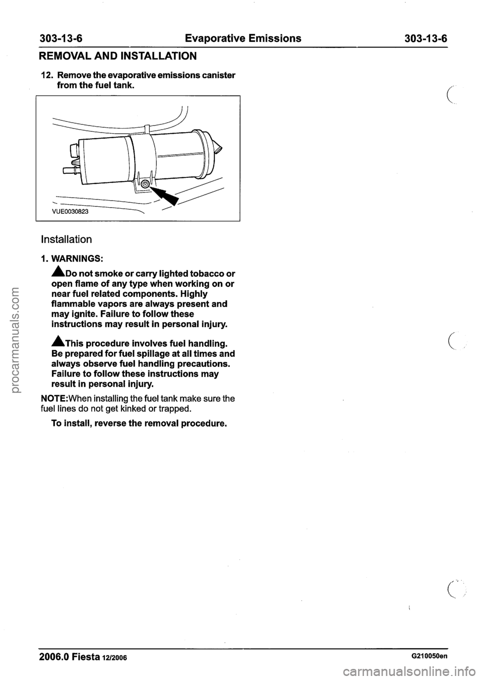
12. Remove the evaporative emissions canister
from the fuel tank.
Installation
1. WARNINGS:
ADO not smoke or carry lighted tobacco or
open flame of any type when working on or
near fuel related components. Highly
flammable vapors are always present and
may ignite. Failure to follow these
instructions may result in personal injury.
A~his procedure involves fuel handling.
Be prepared for fuel spillage at all times and
always observe fuel handling precautions.
Failure to follow these instructions may
result in personal injury.
N0TE:When installing the fuel tank make sure the
fuel lines do not get kinked or trapped.
To install, reverse the removal procedure.
2006.0 Fiesta 1212006 G210050en
procarmanuals.com
Page 940 of 1226
Electronic Engine Controls
DIAGNOSIS AND TESTING
detected in either the STFT or LTFT, and it is still
present on a second trip, the MIL will be switched
on.
Heated Oxygen Sensor (H02S) Monitor (All except
vehicles with diesel engine)
This monitors the operation of the pre (upstream)
and post (downstream) catalytic converter
H02S
sensors. It will detect deviations in airlfuel ratios
(AFR) and sensor faults.
The
H02S will cause emission increase when its
response time increases too much. To diagnose
a sensor a period is measured and the number of
leanlrich transitions are counted. The sum of valid
periods is then calculated. To avoid
non-representative measurements, the period is
valid only if the
H02S has been below a low
threshold and above a high threshold between 2
consecutive leanlrich transitions.
A failure is
declared when the sum of the measured periods
exceeds the sum of the corresponding limit (held
within the PCM) and the MIL is illuminated.
Catalytic Converter Efficiency Monitor (All except
vehicles with diesel engine)
The efficiency of a catalytic converter is measured
by its ability to store and later release oxygen to
convert harmful gases. The efficiency is reduced
if the converter becomes contaminated as it ages,
and at high gas flow rates, because the exhaust
gas does not remain in the converter long enough
to complete the conversion process. switches
over or until the end of a delay. If this
delay expires or the sensor does not switch, the
sensor is treated as failed.
Combustion Noise Monitor (Vehicles with common
rail fuel injection)
In diesel variants, the Combustion Noise Monitor
is used to trim the fuel injection pulse lengths. Each
fuel injector has an associated set of correction
data that is determined during a production end of
line test. The Combustion Noise Monitor is used
to determine how the fuel injector characteristic
changes from this initial calibration over the life of
the fuel injector.
EGR Monitor (Vehicles with diesel engine)
The functionality of the EGR system is checked by
comparing either the MAP sensor output or EGR
valve lift potentiometer output (depending upon
application) with expected values.
Diagnostic Requirements
Vehicles equipped with EOBD, can be diagnosed
using the WDS. In order for the EOBD system to
be invoked, a number of criteria must be met. After
any repair, which could affect emissions, a trip must
be carried out on the vehicle, to make sure that
engine management system operates correctly.
Malfunction Indicator Lamp (MIL)
The MIL is located in the instrument cluster and is
fitted to alert the driver to the fact that an abnormal
This monitor checks for the oxygen storage condition
has developed in the engine management
capacity (OSC) of the catalytic converter. During system,
that is having an adverse effect on
a controlled period, the catalyst monitor sensor emissions.
In cases of misfires which are likely to
signal is analyzed to evaluate the OSC of the cause
catalytic converter damage, it is switched
catalyst. It represents the quantity of oxygen that on immediately.
With all other faults it will illuminate
is really used for the oxidation-reduction reaction continuously
from the second trip after the condition
by the catalytic converter If a fault has occurred occurred.
Under normal operation it should
with the catalyst monitor sensor during the catalyst illuminate
at key-on and go out almost as soon as
diagnosis, a sensor diagnosis is carried out. During the
engine is started.
the controlled diagnosis phase, the catalyst monitor
Diagnostic Trouble Codes (DTCs) sensor activity is measured and is compared to the
OSC of the catalyst. If this activity is high (low The
DTCs given
by the PCM are standardized,
0SC)theMILwillbeilluminated.Ifthroughoutthe whichmeansthatgenericscantoolscanread
controlled phase, repeated several times, the results from
all vehicles.
downstream sensor output has not moved, the
closed loop mode is delayed in order to test the
sensor. If the catalyst monitor sensor is set to rich,
the injection time is forced to lean and conversely
if the downstream sensor is set to lean, the
injection time is forced to rich until the sensor
2006.0 Fiesta 1212006 G384566en
procarmanuals.com
Page 941 of 1226
303-1 4-1 7 Electronic Engine Controls 303-1 4-1 7
DIAGNOSIS AND TESTING
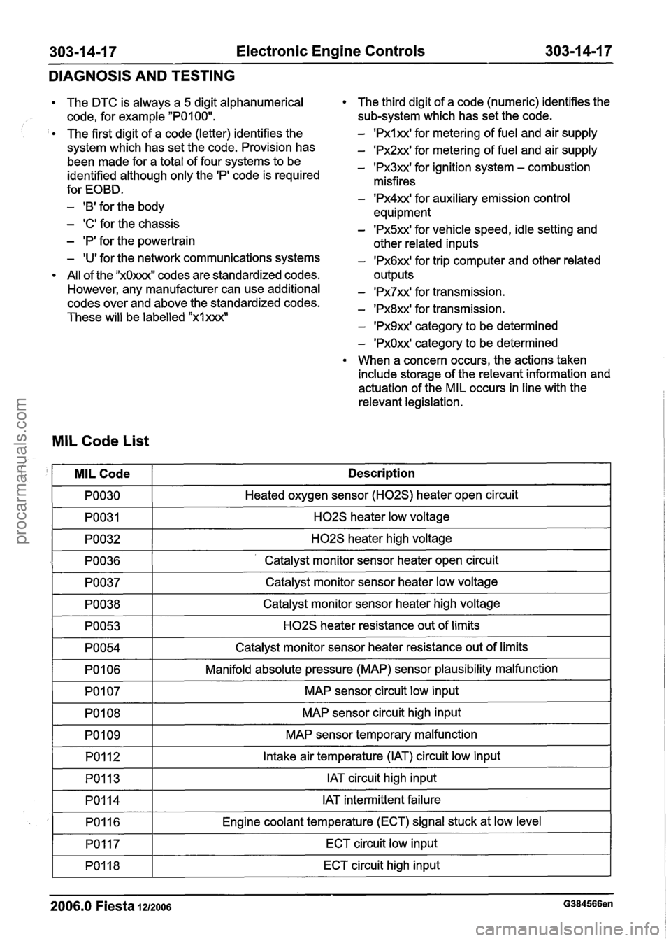
The DTC is always a 5 digit alphanumerical
code, for example
"POI 00".
The first digit of a code (letter) identifies the
system which has set the code. Provision has
been made for a total of four systems to be
identified although only the
'PI code is required
for EOBD.
- 'B' for the body
- 'C' for the chassis
- 'P' for the powertrain
- 'U' for the network communications systems
All of the
"xOxxxW codes are standardized codes.
However, any manufacturer can use additional
codes over and above the standardized codes.
These will be labelled
"xlxxx"
The third digit of a code (numeric) identifies the
sub-system which has set the code.
- 'Pxlxx' for metering of fuel and air supply
- 'Px2xx' for metering of fuel and air supply
- 'Px3xx' for ignition system - combustion
misfires
- 'Px4xx' for auxiliary emission control
equipment
- 'Px5xx' for vehicle speed, idle setting and
other related inputs
- 'Px6xx' for trip computer and other related
outputs
- 'Px7xx' for transmission.
- 'Px8xx' for transmission.
- 'Px9xx' category to be determined
- 'PxOxx' category to be determined
When a concern occurs, the actions taken
include storage of the relevant information and
actuation of the MIL occurs in line with the
relevant legislation.
MIL Code List
I PO030 I Heated oxygen sensor (H02S) heater open circuit I
! '
-1 H02S heater low voltage I
I PO032 I H02S heater high voltage I
MILCode
PO036 1- ' Catalyst monitor sensor heater open circuit I
Description
PO037
I PO054 I Catalyst monitor sensor heater resistance out of limits I
Catalyst monitor sensor heater low voltage
PO038
PO053
I PO106 I Manifold absolute pressure (MAP) sensor plausibility malfunction I
-
Catalyst monitor sensor heater high voltage
H02S heater resistance out of limits
I PO107 I MAP sensor circuit low input I
PO108
PO1 09 MAP sensor
circuit high input
MAP sensor temporary malfunction
PO1 12
PO113
I PO117 I ECT circuit low input I
Intake air temperature (IAT) circuit low input
IAT circuit high input
I
2006.0 Fiesta 1212006 G384566en
PO114
PO1 16
PO118
IAT intermittent failure
Engine coolant temperature (ECT) signal stuck at low level
ECT circuit high input
procarmanuals.com
Page 1188 of 1226
31 0-00-2 Fuel System - General Information 31 0-00-2
DIAGNOSIS AND TESTING
Fuel System - 1.3L Duratec-8V (Rocam)/l.25L Duratec-1 6V
(Sigma)/2.0L Duratec-HE (M14)/1.4L Duratec-I 6V
(Sigma)/l.GL Duratec-1 6V (Sigma)
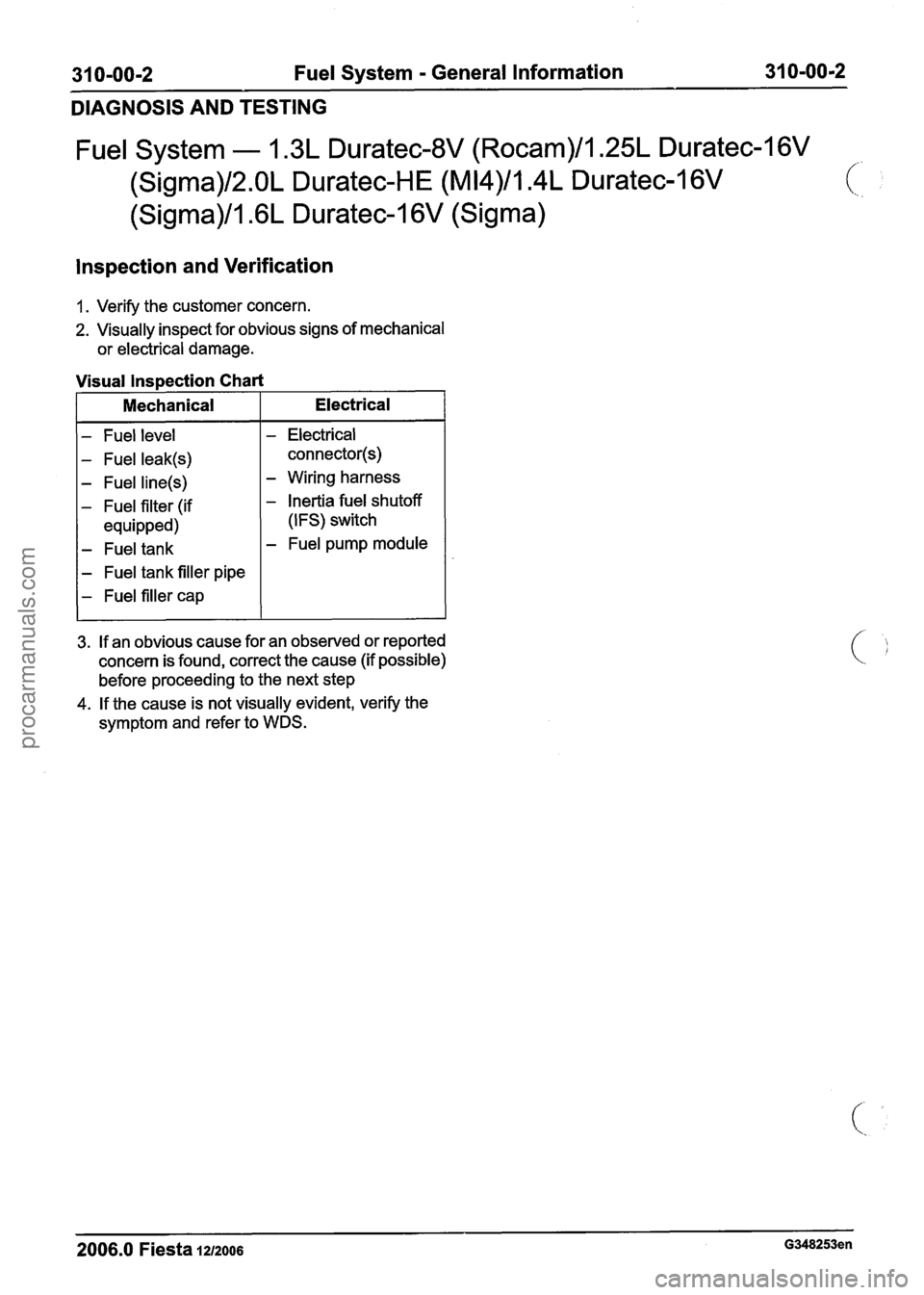
lnspection and Verification
1. Verify the customer concern.
2. Visually inspect for obvious signs of mechanical
or electrical damage.
- Fuel level
- Fuel leak(s)
- Fuel line(s)
- Fuel filter (if
equipped)
- Fuel tank
- Fuel tank filler pipe
- Fuel filler cap
Visual lnspection Chart
- Electrical
connector(s)
- Wiring harness
- Inertia fuel shutoff
(IFS) switch
- Fuel pump module
I Mechanical
3. If an obvious cause for an observed or reported
concern is found, correct the cause (if possible)
before proceeding to the next step
4. If the cause is not visually evident, verify the
symptom and refer to WDS.
Electrical
-
2006.0 Fiesta 1212006 G348253en
procarmanuals.com
Page 1191 of 1226
31 0-00-5 Fuel System - General Information 31 0-00-5
GENERAL PROCEDURES
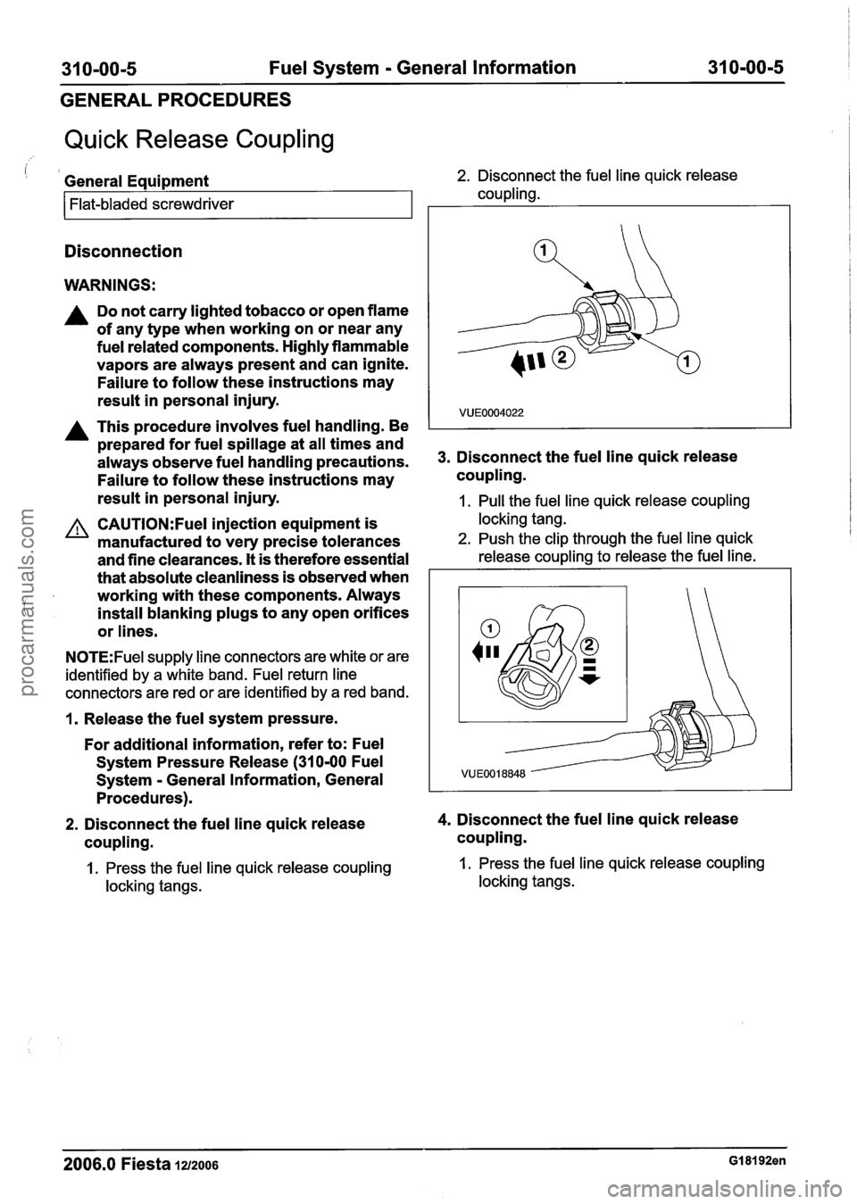
Quick Release Coupling
i 1 General Equipment 2. Disconnect the fuel line quick release
coupling.
Flat-bladed screwdriver
Disconnection
WARNINGS:
A Do not carry lighted tobacco or open flame
of any type when working on or near any
fuel related components. Highly flammable
vapors are always present and can ignite.
Failure to follow these instructions may
result in personal injury.
A This procedure involves fuel handling. Be
prepared for fuel spillage at all times and
always observe fuel handling precautions.
Failure to follow these instructions may
result in personal injury. 3.
Disconnect the fuel line quick release
coupling.
1. Pull the fuel line quick release coupling
CAUTI0N:Fuel injection equipment is locking tang.
manufactured to very precise tolerances 2. Push the clip through the fuel line quick
and fine clearances. It is therefore essential release coupling to release the fuel line.
that absolute cleanliness is observed when I
i
working with these components. Always
install blanking plugs to any open orifices
or lines.
N0TE:Fuel supply line connectors are white or are
identified by a white band. Fuel return line
connectors are red or are identified by a red band.
1. Release the fuel system pressure.
For additional information, refer to: Fuel
System Pressure Release (31
0-00 Fuel
Svstem - General Information, General
2. Disconnect the fuel line quick release 4. Disconnect the fuel line quick release
coupling. coupling.
1. Press the fuel line quick release coupling 1. Press the fuel line quick release coupling
locking tangs. locking tangs.
2006.0 Fiesta 1212006 GI 81 92en
procarmanuals.com
Page 1192 of 1226
31 0-00-6 Fuel System - General Information 31 0-00-6
GENERAL PROCEDURES
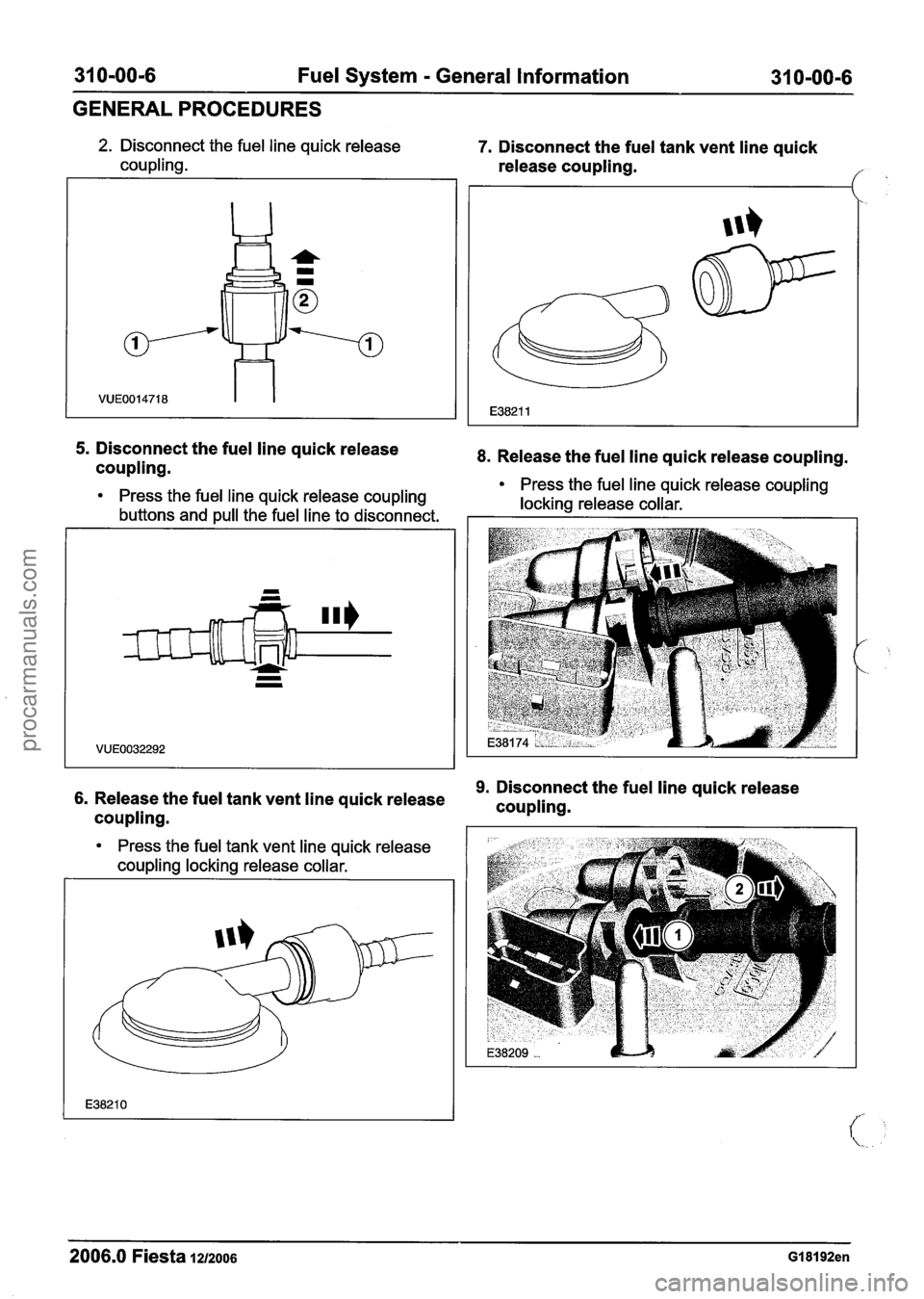
5. Disconnect the fuel line quick release
coupling.
2. Disconnect the fuel line quick release 7. Disconnect the fuel tank vent line quick
coupling. release coupling.
8. Release the fuel line quick release coupling.
-
4 =
b
.-
VUE0014718
- - Press the fuel line quick release coupling
Press the fuel line quick release coupling
locking release collar.
buttons and pull the fuel line to disconnect.
63
E38211
9. Disconnect the fuel line quick release 6. Release the fuel tank vent line quick release
coupling.
Press the fuel tank vent line quick release
coupling locking release collar.
2006.0 Fiesta 1212006 GI 81 92en
procarmanuals.com
Page 1193 of 1226
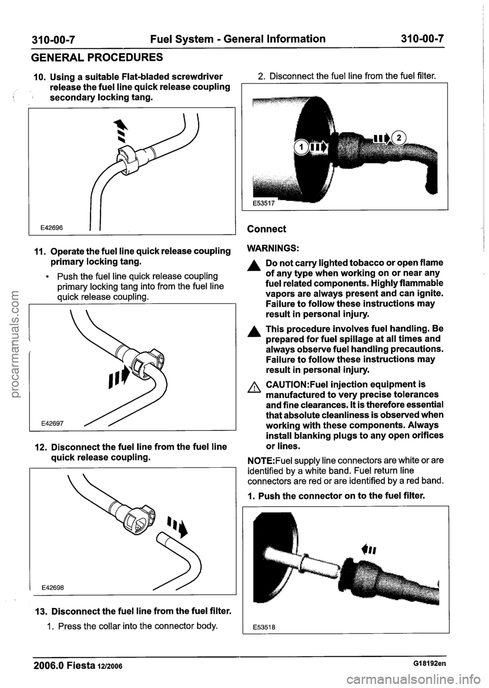
31 0-00-7 Fuel System - General Information 31 0-00-7
GENERAL PROCEDURES
10. Using a suitable Flat-bladed screwdriver 2. Disconnect the fuel line from the fuel filter.
release the fuel line quick release coupling
( secondary locking tang.
Connect
11. Operate the fuel line quick release coupling WARNINGS:
primary locking tang.
Push the fuel line quick release coupling
primary locking tang into from the fuel line
quick release coupling.
12. Disconnect the fuel line from the fuel line
quick release coupling.
13. Disconnect the fuel line from the fuel filter.
1 . Press the collar into the connector body.
Do not carry lighted tobacco or open flame
of any type when working on or near any
fuel related components. Highly flammable
vapors are always present and can ignite.
Failure to follow these instructions may
result in personal injury.
A This procedure involves fuel handling. Be
prepared for fuel spillage at all times and
always observe fuel handling precautions.
Failure to follow these instructions may
result in personal injury.
A CAUTI0N:Fuel injection equipment is
manufactured to very precise tolerances
and fine clearances.
It is therefore essential
that absolute cleanliness is observed when
working with these components. Always
install blanking plugs to any open orifices
or lines.
N0TE:Fuel supply line connectors are white or are
identified by a white band. Fuel return line
connectors are red or are identified by a red band.
1. Push the connector on to the fuel filter.
2006.0 Fiesta 1212006 GI 81 92en
procarmanuals.com