Fuel line FORD FIESTA 2007 Repair Manual
[x] Cancel search | Manufacturer: FORD, Model Year: 2007, Model line: FIESTA, Model: FORD FIESTA 2007Pages: 1226, PDF Size: 61.26 MB
Page 1194 of 1226
31 0-00-8 Fuel System - General Information 31 0-00-8
GENERAL PROCEDURES
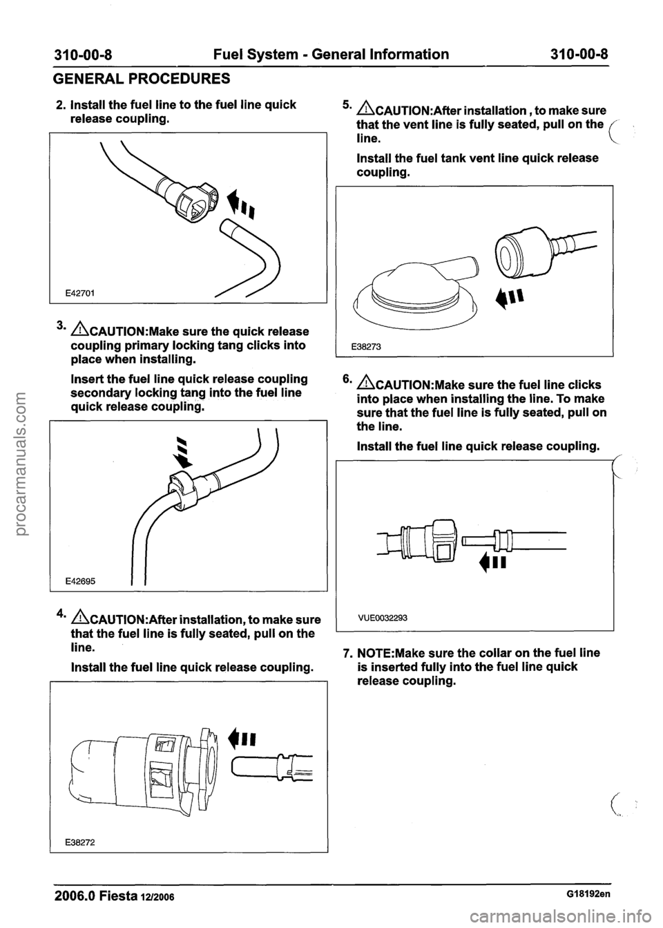
2. Install the fuel line to the fuel line quick
release coupling. 5m &AUTION:A~~~~ installation , to make sure
that the vent line is fully seated, pull on the
line.
3m &AUTION:M~~~ sure the quick release
coupling primary locking tang clicks into
place when installing. Install the fuel
tank vent line quick release
coupling.
Insert the fuel line quick release coupling
secondary locking tang into the fuel line
&AUTION:M~~~ sure the fuel line clicks
into place when installing the line. To make
quick release coupling.
sure that the fuel line is fully seated, pull on
the line.
4m &AUTION:A~~~~ installation, to make sure
that the fuel line is fully seated, pull on the Install the
fuel line quick release coupling.
/'
line. 7. N0TE:Make sure the collar on the fuel line
Install the fuel line quick release coupling. is
inserted fully into the fuel line quick
release coupling.
2006.0 Fiesta 1212006 GI 81 92en
procarmanuals.com
Page 1195 of 1226

31 0-00-9 Fuel System - General Information 31 0-00-9
GENERALPROCEDURES
Install the fuel line quick release coupling. 2. Press the fuel line quick release coupling
locking tang into position.
VUE0004016
8. N0TE:Make sure the collar on the fuel line
is inserted fully into the fuel line quick
release coupling before the locking tang is
locked.
lnstall the fuel line quick release coupling.
1. lnstall the fuel line quick release coupling
locking tang.
2. Rotate the fuel line quick release coupling
locking tang into position.
9. N0TE:Make sure the collar on the fuel line
is inserted fully into the fuel line quick
release coupling before the locking tang is
locked.
Install the fuel line quick release coupling.
I. lnstall the fuel line quick release coupling.'
2006.0 Fiesta 1212006 GI 81 92en
procarmanuals.com
Page 1196 of 1226
31 0-00-1 0 Fuel System - General Information 31 0-00-1 0
GENERALPROCEDURES
Fuel System Pressure Check - 2.OL Duratec-HE (M14)
Special Tool(s)
I Test Hose for 31 0-025
I I Test Hose for 31 0-025 1
General Equipment 1
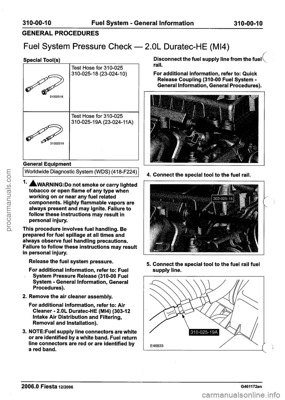
Disconnect the fuel supply line from the fuel(
rail.
For additional information, refer to: Quick
Release Coupling (310-00 Fuel System
-
General Information, General Procedures).
Irn AWARNING:D~ not smoke or carry lighted
tobacco or open flame of any type when
working on or near any fuel related
components. Highly flammable vapors are
always present and may ignite. Failure to
follow these instructions may result in
personal injury.
This procedure involves fuel handling. Be
prepared for fuel spillage at all times and
always observe fuel handling precautions.
Failure to follow these instructions may result
in personal injury.
Release the fuel system pressure.
For additional information, refer to: Fuel
- System Pressure Release (310-00 Fuel
System
- General Information, General
Procedures).
2. Remove the air cleaner assembly.
For additional information, refer to: Air
Cleaner
- 2.OL Duratec-HE (M14) (303-12
Intake Air Distribution and Filtering,
Removal and Installation).
3.
N0TE:Fuel supply line connectors are white
or are identified by a white band. Fuel return
line connectors are red or are identified by
a red band.
5. Connect the special tool to the fuel rail fuel
supply line.
- - -- - - -
2006.0 Fiesta 1212006 G461172en
procarmanuals.com
Page 1197 of 1226
31 0-00-1 I Fuel System - General Information 31 0-00-1 1
GENERAL PROCEDURES
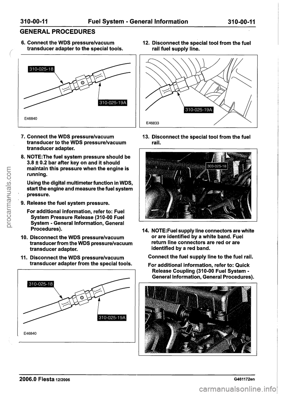
6. Connect the WDS pressurelvacuum 12. Disconnect the special tool from the fuel
/' transducer adapter to the special tools.
rail fuel supply line.
7. Connect the WDS pressurelvacuum
transducer to the WDS pressurelvacuum
transducer adapter.
8. N0TE:The fuel system pressure should be
3.8 f 0.2 bar after key on and it should
maintain this pressure when the engine is
running.
Using the digital multimeter function in WDS,
start the engine and measure the fuel system
pressure.
(,
9. Release the fuel system pressure.
For additional information, refer to: Fuel
System Pressure Release
(31 0-00 Fuel
System
- General Information, General
Procedures).
10. Disconnect the WDS pressurelvacuum
transducer from the WDS pressurelvacuum
transducer adapter.
11. Disconnect the WDS pressurelvacuum
transducer adapter from the special tools.
2006.0 Fiesta 1212006
13. Disconnect the special tool from the fuel
rail.
14. N0TE:Fuel supply line connectors are white
or are identified by a white band. Fuel
return line connectors are red or are
identified by a red band.
Connect the fuel supply line to the fuel rail.
For additional information, refer to: Quick
Release Coupling
(310-00 Fuel System -
General Information, General Procedures).
procarmanuals.com
Page 1199 of 1226
31 0-01 -1 Fuel Tank and Lines 31 0-01 -1
1 SECTION 31 0-01 Fuel Tank and Lines
VEHICLE APPLICATION:2006.0 Fiesta
CONTENTS
SPECIFICATIONS
Specifications.. . . . . . . . . . . . . . . . . . . . . . . . . . . . . . . . . . . . . . . . . . . . . . . . . . . . . . . . . . . . . . . . . . . . . . . . . . . . . . . . . . . . . . . . . . . . . . . . . . . . . . . . . . . . . . . . . . . . .
PAGE
DESCRIPTION AND OPERATION
Fuel Tank and Lines - 1.25L Duratec-I 6V (Sigma)/l.4L Duratec-1 6V (Sigma)/l .6L
Duratec-I 6V (Sigma) ...... . . .. .. .... .. .... . . .... . . . . .... ...... .. .. . . . . ...... . . . . ........ .. .. .. .. . . . . . . . ... .. . . . . . . . . . . .. .... 31 0-01 -3
Overview..
. . . . . . . . . . . . . . . . . . . . . . . . . . . . . . . . . . . . . . . . . . . . . . . . . . . . . . . . . . . . . . . . . . . . . . . . . . . . . . . . . . . . . . . . . . . . . . . . . . . . . . . . . . . . . . . . . . . . . . . . . . . 3 1 0-0 1 -3
DIAGNOSIS AND TESTING
. Fuel Tank and Lines ........................................................................\
....................................
REMOVAL AND INSTALLATION
Fuel Tank ..... . . ...... . . . ... . . ...... .... .. . . . . . . . . . . . . . . . . . . . . . . . . . ...... . . . . . . . . . . . . . . . . . . . (23 554 0)
31 0-01 -6
Fuel Pump Module. ........................................................................\
........ . (23 534 0)
31 0-01 -1 1
Fuel Tank Filler Pipe ........................................................................\
............... (23 572 0) 31 0-01-12
Fuel Level Sensor ..... . . . . . . . . . .. .... .. .. .... .. .. . . .. .. .. . . . . . . . . . . . . .. ...... .. . . .. .... . . .. . . . . .. . . .. .... . ... .. .. .. . . .. . . . . . . .. . 31 0-01 -1 4
Fuel Level Resistor Card ..... . . . . .. .. . . .. . . . . .. . . . . .. ...... . . . . . . . ..... . . . ..... . . . . . . . . . . . . . . . . . . . . . . 31 0-01 -1 5
procarmanuals.com
Page 1200 of 1226
31 0-01 -2 Fuel Tank and Lines 31 0-01 -2
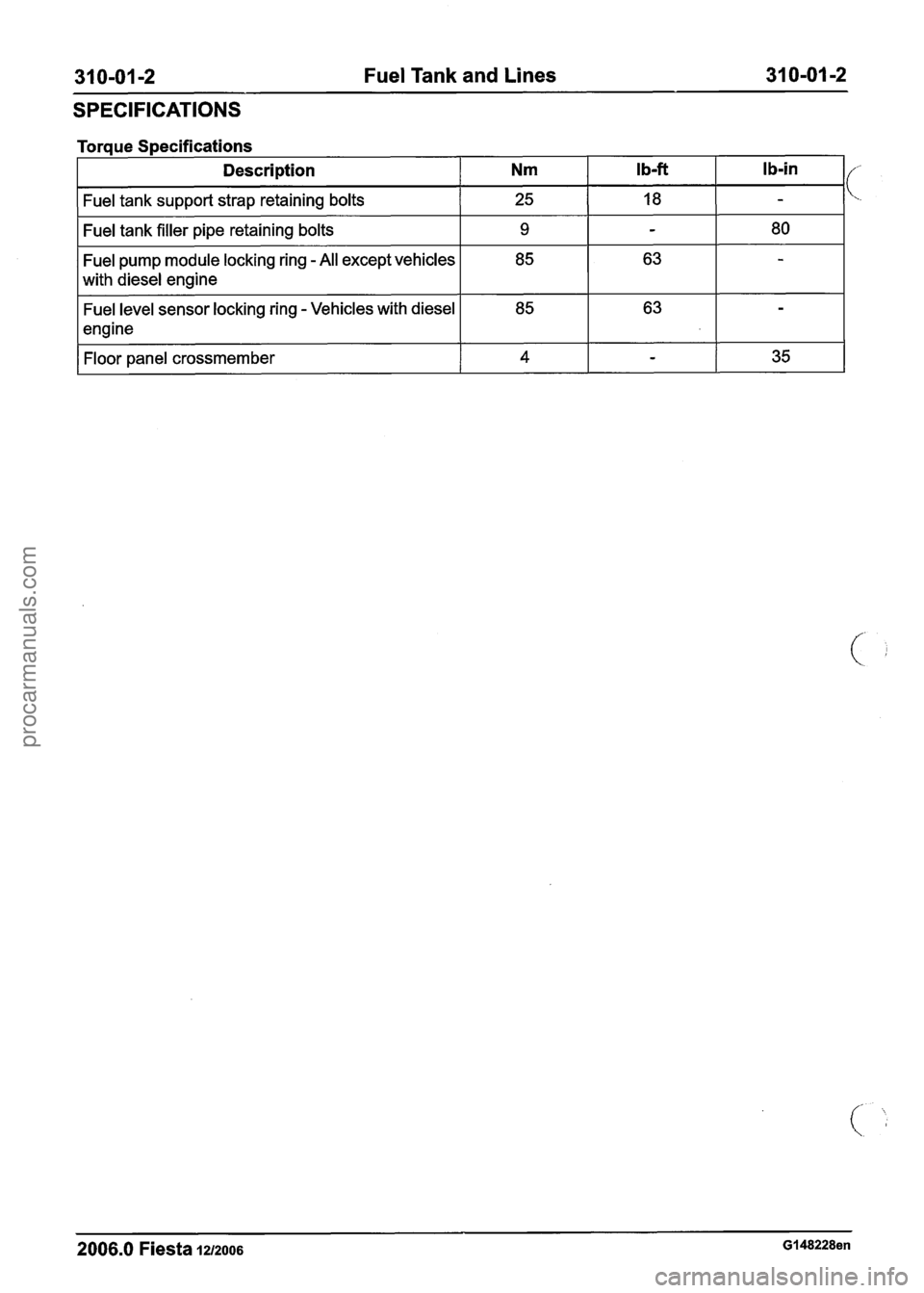
SPECIFICATIONS
Torque Specifications
Description
Nm Ib-ft I b-in I/
Fuel tank support strap retaining bolts I 25 I 18 I -
Fuel tank filler pipe retaining bolts I 9 I - I 80 I
Fuel pump module locking ring - All except vehicles
with diesel engine
Fuel level sensor locking ring
- Vehicles with diesel
engine
Floor panel crossmember
I 4 I - I 35 I
2006.0 Fiesta 1212006 GI 48228en
procarmanuals.com
Page 1201 of 1226

31 0-01 -3 Fuel Tank and Lines 31 0-01 -3
DESCRIPTION AND OPERATION
Fuel Tank and Lines - 1.25L Duratec-1 6V (Sigma)/l.4L
Duratec-1 6V (Sigma)/l .6L Duratec-1 6V (Sigma)
Overview
Item Description In the
event of an accident, the fuel cut-off safety
11 Tank breather pipe I
1
2
3
1 5 1Tankfiller neck I
Fuel return line
1 6 I Activated charcoal canister I
switch interrupts the power supply so that no more
fuel can be supplied.
Non-return valve, Evaporative Emission
(EVAP) system
Fuel pump unit
1 7 1 Fuel filter I
It is located behind a cover on the right-hand
A-pillar in the footwell next to the central junction
box.
1 8 1 Fuel feed line I
The fuel tank holds 45 litres.
a The fuel pump unit is located in the fuel tank. It
consists of the fuel pump and the sender for the
fuel gauge.
The fuel pump is electrically controlled through the
The fuel tank must be removed before the fuel
fuel cut-off safety switch. pump
unit can be removed.
2006.0 Fiesta 1212006 G207055en
procarmanuals.com
Page 1202 of 1226

31 0-01 4 Fuel Tank and Lines 31 0-01 -4 --
DESCRIPTION AND OPERATION
Care must be taken on installation, that the arrows
on the fuel tank and the fuel pump unit point at
each other.
If the alignment is wrong, then the fuel level shown
may be incorrect.
2006.0 Fiesta 1212006 G207055en
procarmanuals.com
Page 1203 of 1226
31 0-01 -5 Fuel Tank and Lines 31 0-01 -5
DIAGNOSIS AND TESTING
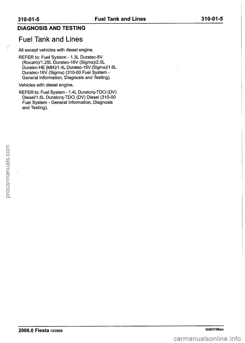
Fuel Tank and Lines
All except vehicles with diesel engine,
REFER to:
Fuel System - 1.3L Duratec-8V
(Rocam)/l.25L Duratec-1 6V (Sigma)/Z.OL
Duratec-HE (M14)/1.4L Duratec-1 6V (Sigma)/l .6L
Duratec-1 6V (Sigma) (31 0-00 Fuel System -
General Information, Diagnosis and Testing).
Vehicles with diesel engine,
REFER to:
Fuel System - 1.4L Duratorq-TDCi (DV)
Dieselll.6L Duratorq-TDCi (DV) Diesel (31 0-00
Fuel System - General Information, Diagnosis
and Testing).
2006.0 Fiesta 1212006 G453196en
procarmanuals.com
Page 1204 of 1226
31 0-01 -6 Fuel Tank and Lines 31 0-01 -6
REMOVAL AND INSTALLATION
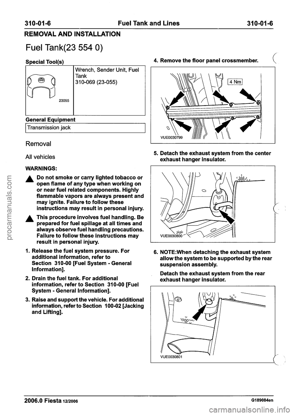
Fuel Tank(23 554 0)
Special Tool(s)
I I Wrench, Sender Unit, Fuel
General Equipment
I Transmission jack I
Removal
All vehicles
WARNINGS:
A Do not smoke or carry lighted tobacco or
open flame of any type when working on
or near fuel related components. Highly
flammable vapors are always present and
may ignite. Failure to follow these
instructions may result in personal injury.
A This procedure involves fuel handling. Be
prepared for fuel spillage at all times and
always observe fuel handling precautions.
Failure to follow these instructions may
4. Remove the floor panel crossmember. (
5. Detach the exhaust system from the center
exhaust hanger insulator.
result in personal injury.
I
1. Release the fuel system pressure. For 6. N0TE:When detaching the exhaust system
additional information, refer to
allow the system to be supported by the rear
Section
31 0-00 [Fuel System - General
suspension assembly.
Information].
. Detach the exhaust system from the rear 2. Drain the fuel tank. For additional
exhaust hanger insulator.
information, refer to Section
31 0-00 [Fuel
System
- General Information].
3. Raise and support the vehicle. For additional
information, refer to Section
100-02 [Jacking
and Lifting].
2006.0 Fiesta 1212006 GI 89084en
procarmanuals.com