Fuel line FORD FIESTA 2007 Owner's Manual
[x] Cancel search | Manufacturer: FORD, Model Year: 2007, Model line: FIESTA, Model: FORD FIESTA 2007Pages: 1226, PDF Size: 61.26 MB
Page 598 of 1226
Engine - 1.25L Duratec-1 6V (Sigma)ll.4L
303-01 A-I 22 Duratec-1 6V (Sigma)/l .6L Duratec-1 6V (Sigma)
303-01 A-1 22
INSTALLATION
Engine
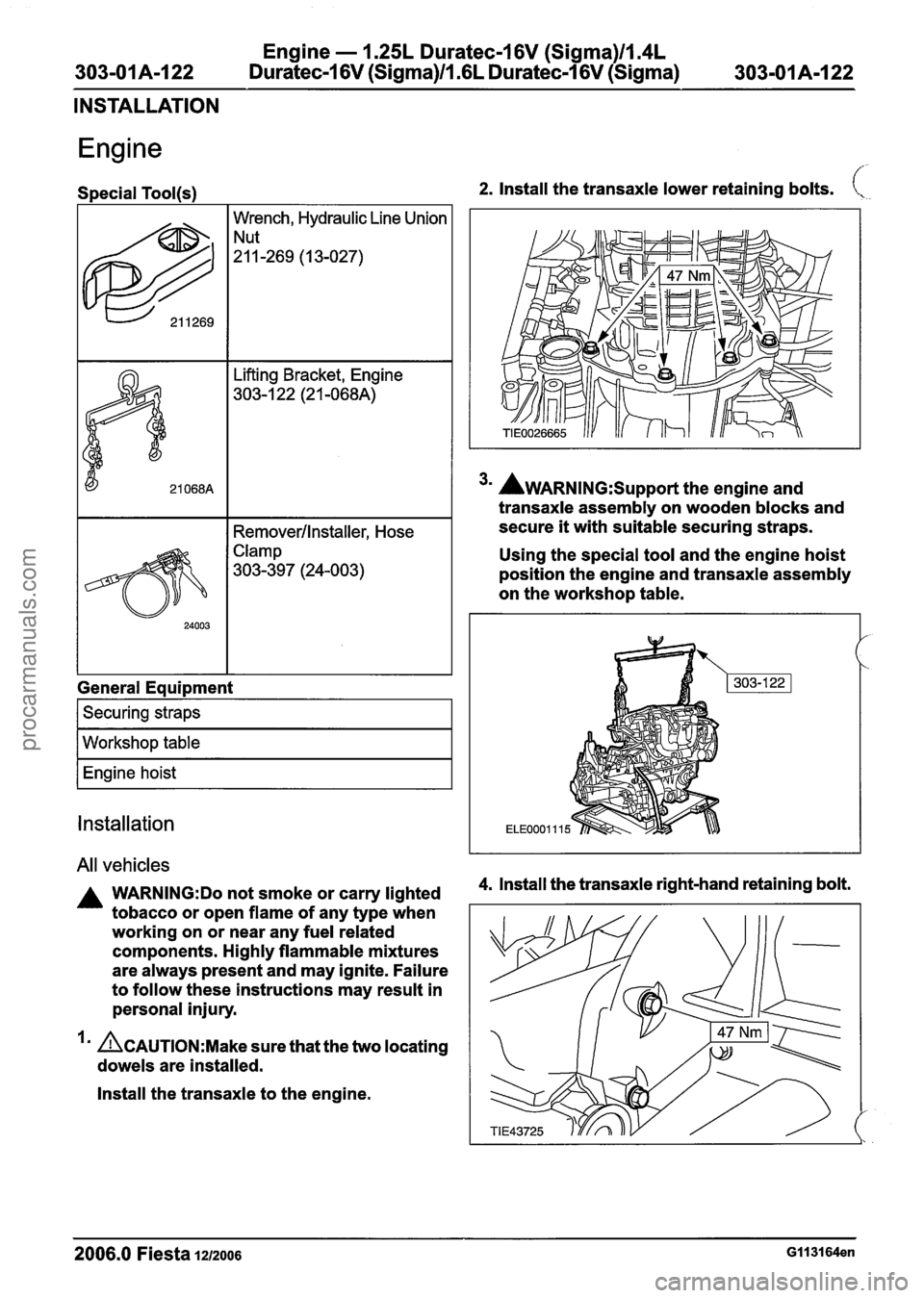
Special Tool(s) 2. Install the transaxle lower retaining bolts. \.,
622
I I Remover/lnstaller, Hose
Wrench,
Hydraulic Line Union
"-269 (I 3-027)
- --
21 068A
Clamp
303-397 (24-003)
ift tins racket, Engine
303-1 22 (2 1 -068A)
General Equipment
I Securing straps I
I Workshop table I
I Engine hoist I
Installation
All vehicles
A WARN1NG:Do not smoke or carry lighted
tobacco or open flame of any type when
working on or near any fuel related
components. Highly flammable mixtures
are always present and may ignite. Failure
to follow these instructions may result in
personal injury.
I' ACAUTION:M~~~ sure that the two locating
dowels are installed.
Install the transaxle to the engine.
3m AWARNING:S~~~~~~ the engine and
transaxle assembly on wooden blocks and
secure
it with suitable securing straps.
Using the special tool and the engine hoist
position the engine and transaxle assembly
on the workshop table.
4. lnstall the transaxle right-hand retaining bolt.
2006.0 Fiesta 1212006 GII 3164en
procarmanuals.com
Page 607 of 1226
Engine - 1.25L Duratec-1 6V (Sigma)ll.4L
303-OIA-I31 Duratec-1 6V (Sigma)/l .6L Duratec-1 6V (Sigma) 303-01 A-1 31
INSTALLATION
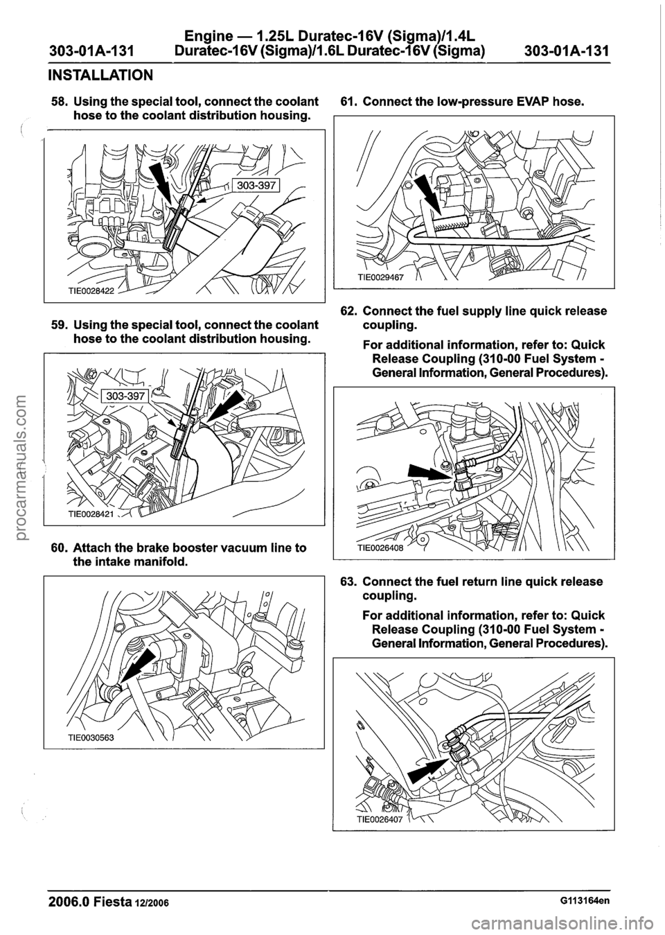
58. Using the special tool, connect the coolant 61. Connect the low-pressure EVAP hose.
hose to the coolant distribution housing.
62. Connect the fuel supply line quick release
59. Using the special tool, connect the coolant coupling.
hose to the coolant distribution housing.
For additional information, refer to: Quick
60. Attach the brake booster vacuum line to
the intake manifold. Release
Coupling (310-00 Fuel System
-
General Information, General Procedures).
63. Connect the fuel return line quick release
coupling.
For additional information, refer to: Quick
Release Coupling (310-00 Fuel System
-
General Information, General Procedures).
2006.0 Fiesta 1212006 GII 3164en
procarmanuals.com
Page 608 of 1226
Engine - I .25L Duratec-1 6V (Sigma)ll.4L
303-01 A-1 32 Duratec-1 6V (Sigma)ll .6L
Duratec-1 6V (Sigma) 303-01 A-1 32
INSTALLATION
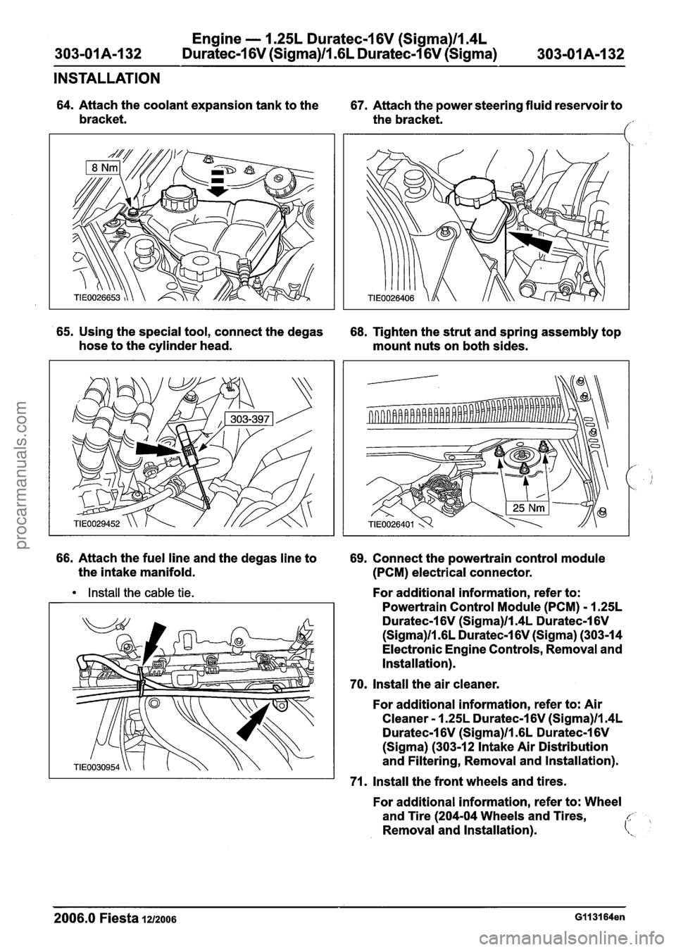
64. Attach the coolant expansion tank to the
67. Attach the power steering fluid reservoir to
bracket. the bracket.
1'
65. Using the special tool, connect the degas
68. Tighten the strut and spring assembly top
hose to the cylinder head.
mount nuts on both sides.
66. Attach the fuel line and the degas line to
69. Connect the powertrain control module
the intake manifold.
(PCM) electrical connector.
Install the cable tie. For additional information, refer to:
Powertrain Control Module (PCM)
- 1.25L
Duratec-1 6V (Sigma)ll.4L Duratec-1 6V
(Sigma)ll .6L Duratec-1 6V (Sigma) (303-14
Electronic Engine Controls, Removal and
Installation).
70. Install the air cleaner.
For additional information, refer to: Air
Cleaner
- 1.25L Duratec-1 6V (Sigma)ll.4L
Duratec-1 6V (Sigma)ll .6L Duratec-1 6V
(Sigma) (303-12 Intake Air Distribution
and Filtering, Removal and Installation).
71. Install the front wheels and tires.
For additional information, refer to: Wheel
and Tire (204-04 Wheels and Tires,
c,
Removal and Installation). (\,
2006.0 Fiesta 121zo06 GII 31 64en
procarmanuals.com
Page 621 of 1226
Engine - 1.25L Duratec-1 6V (Sigma)ll.4L
303-01 A-1 45 Duratec-1 6V (Sigma)ll .6L
Duratec-1 6V (Sigma) 303-01 A-1 45
INSTALLATION
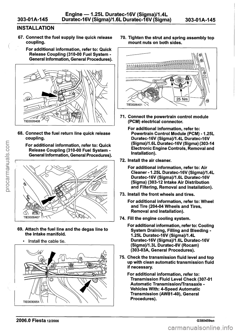
67. Connect the fuel supply line quick release
70. Tighten the strut and spring assembly top
coupling. mount nuts on both sides.
(: , For additional information, refer to: Quick
Release Coupling (310-00 Fuel System
-
General Information, General Procedures).
68. Connect the fuel return line quick release
coupling.
For additional information, refer to: Quick
Release Coupling (310-00 Fuel System
-
General Information, General Procedures).
69. Attach the fuel line and the degas line to
the intake manifold.
Install the cable tie.
71. Connect the powertrain control module
(PCM) electrical connector.
For additional information, refer to:
Powertrain Control Module (PCM)
- 1.25L
Duratec-1 6V (Sigma)llm4L Duratec-1 6V
(Sigma)ll.GL Duratec-1 6V (Sigma) (303-14
Electronic Engine Controls, Removal and
Installation).
72, Install the air cleaner.
For additional information, refer to: Air
Cleaner
- 1.25L Duratec-1 6V (Sigma)ll.4L
Duratec-1 6V (Sigma)ll.GL Duratec-1 6V
(Sigma) (303-1 2 Intake Air Distribution
and Filtering, Removal and Installation).
73. Install the front wheels and tires.
For additional information, refer to: Wheel
and Tire (204-04 Wheels and Tires,
Removal and lnstallation).
74. Fill the engine cooling system.
For additional information, refer to: Cooling
System Draining, Filling and Bleeding
-
1.25L Duratec-1 6V (Sigma)ll.4L
Duratec-1 6V (Sigma)ll .6L Duratec-1 6V
(Sigma)ll.3L DuratecdV (Rocam)
(303-03A, General Procedures).
75. Check the transmission fluid level and top
up with clean automatic transmission fluid
if necessary.
For additional information, refer to:
Transmission Fluid Level Check (307-01
Automatic
Transmission/Transaxle -
Vehicles With: 4-Speed Automatic
Transmission
(AW81-40), General
Procedures).
--
2006.0 Fiesta 1212006 G380459en
procarmanuals.com
Page 644 of 1226

303-01 8-22 Engine - 2.OL Duratec-HE (M14) 303-01 B-22
IN-VEHICLE REPAIR
9. Detach the wiring harness from the intake
13. Remove the fuel rail.
manifold. For additional information, refer to: Fuel
Rail (303-04 Fuel Charging and Controls
- 2.OL Duratec-HE (M14), Removal and
Installation).
14. Detach the starter motor electrical
connector from the intake manifold.
10. Detach the power steering supply line from
the intake manifold.
15. Disconnect the manifold absolute pressure
(MAP) sensor electrical connector.
,.
.. 1
11. Lower the vehicle.
12. Detach the engine wiring harness from the
valve cover.
1. Unlcip the power steering return line from the
wiring harness bracket.
2. Remove the air cleaner retaining bracket.
16. Detach the evaporative emission valve
3. Unclip the engine wiring harness bracket (EVAP) hose from the intake manifold.
from the intake manifold.
4. Unclip the engine wiring harness from the
intake manifold.
2006.0 Fiesta 12/2006 G451284en
procarmanuals.com
Page 700 of 1226
303-01 B-78 Engine - 2.OL Duratec-HE (M14) 303-01 B-78
REMOVAL
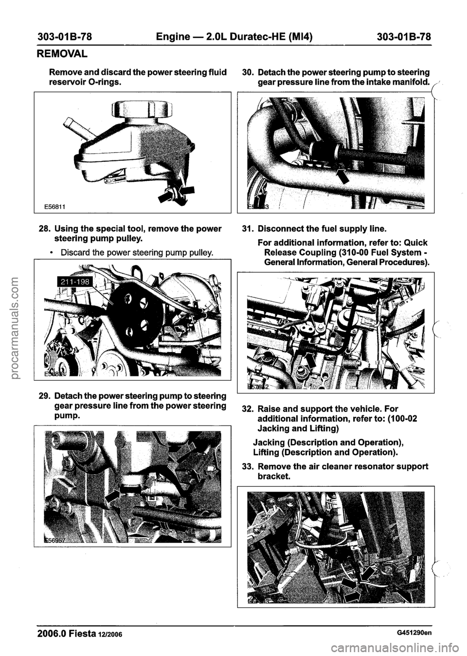
Remove and discard the power steering fluid
30. Detach the power steering pump to steering
reservoir O-rings.
gear pressure line from the intake manifold.
28. Using the special tool, remove the power
31. Disconnect the fuel supply line.
steering pump pulley.
For additional information, refer to: Quick
Discard the power steering pump pulley. Release Coupling (310-00 Fuel System - - - - -
General information, General procedures).
,'-
', .
29. Detach the power steering pump to steering
gearpressurelinefromthepowersteering 32. Raiseands~pportthevehicle~For
Pumpm additional information, refer to: (I 00-02
Jacking and Lifting)
Jacking (Description and Operation),
Lifting (Description and Operation).
33. Remove the air cleaner resonator support
bracket.
2006.0 Fiesta 1212006 G451290en
procarmanuals.com
Page 737 of 1226
303-01 B-I 15 Engine - 2.OL Duratec-HE (M14) 303-01 B-115
INSTALLATION
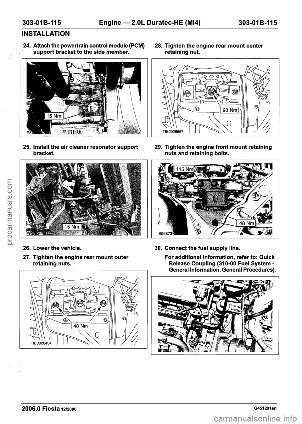
24. Attach the powertrain control module (PCM)
28. Tighten the engine rear mount center
, support bracket to the side member. retaining nut.
25, Install the air cleaner resonator support 29. Tighten the engine front mount retaining
bracket. nuts and retaining bolts.
26. Lower the vehicle.
30. Connect the fuel supply line.
27. Tighten the engine rear mount outer
retaining nuts. For additional information,
refer to: Quick
Release Coupling (310-00 Fuel System
-
General Information, General Procedures).
2006.0 Fiesta 1212006 ~451291 en
procarmanuals.com
Page 801 of 1226
Fuel Charging and Controls - 1.25L
Duratec-1 6V (Sigma)ll.4L Duratec-1 6V
303-04A-3 (Sigma)ll .6L Duratec-1 6V (Sigma) 303-04A-3 - -
DIAGNOSIS AND TESTING
Fuel Charging and Controls
Principles Of Operation
REFER to: Acceleration Control (31 0-02A,
Diagnosis and Testing).
lnspection and Verification
1. Verify the customer concern.
2. Visually inspect for obvious signs of mechanical
or electrical damage.
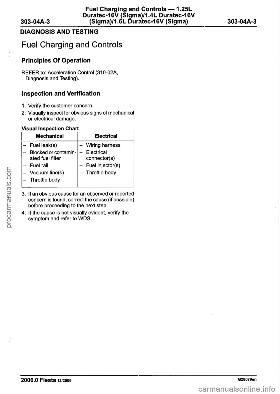
Visual Inspection Chart
I Mechanical I Electrical I
- Fuel leak(s)
- Blocked or contamin-
ated fuel filter
- Fuel rail
- Vacuum line(s)
- Throttle body
- Wiring harness
- Electrical
connector(s)
- Fuel injector(s)
- Throttle body
I
3. If an obvious cause for an observed or reported
concern is found, correct the cause (if possible)
before proceeding to the next step.
4. If the cause is not visually evident, verify the
symptom and refer to WDS.
2006.0 Fiesta 1212006 G28679en
procarmanuals.com
Page 805 of 1226
Fuel Charging and Controls - 1.25L
Duratec-1 6V (Sigma)llI4L Duratec-1 6V
303-04A-7 (Sigma)llI6L Duratec-1 6V (Sigma) 303-04A-7
REMOVAL AND INSTALLATION
Fuel Injection Supply Manifold(23 450 0)
Removal
WARNINGS:
A Do not smoke or carry lighted tobacco or
open flame of any type when working on
or near any fuel related components.
Highly flammable vapors are always
present and can ignite. Failure to follow
these instructions may result in personal
injury.
A This procedure involves fuel handling. Be
prepared for fuel spillage at all times and
always observe fuel handling precautions.
Failure to follow these instructions may
result in personal injury.
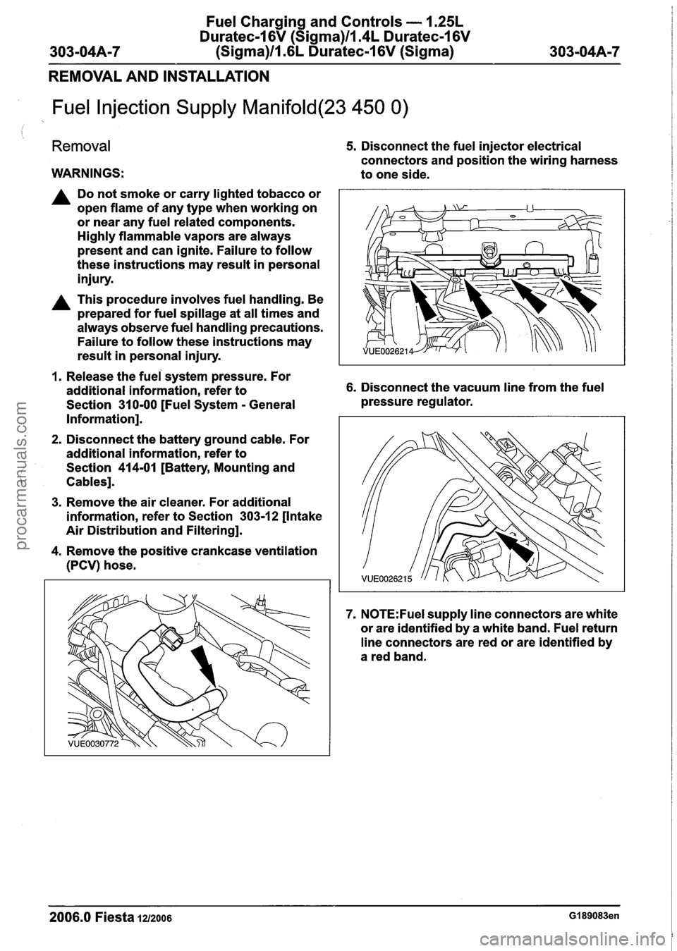
5. Disconnect the fuel injector electrical
connectors and position the wiring harness
to one side.
1. Release the fuei system pressure. For
additional information, refer to 6. Disconnect the vacuum line from the fuel
Section
31 0-00 [Fuel System - General pressure
regulator.
Information].
2. Disconnect the battery ground cable. For
additional information, refer to
Section
414-01 [Battery, Mounting and
Cables].
3. Remove the air cleaner. For additional
information, refer to Section
303-12 [Intake
Air Distribution and Filtering].
4. Remove the positive crankcase ventilation
(PCV) hose.
7. N0TE:Fuel supply line connectors are white
or are identified by a white band. Fuel return
line connectors are red or are identified by
a red band.
2006.0 Fiesta 1212006 GI 89083en
procarmanuals.com
Page 806 of 1226
Fuel Charging and Controls - 1.25L
Duratec-I 6V (Sigma)ll.4L Duratec-I 6V
(Sigma)ll.6L Duratec-1 6V (Sigma)
REMOVAL AND INSTALLATION
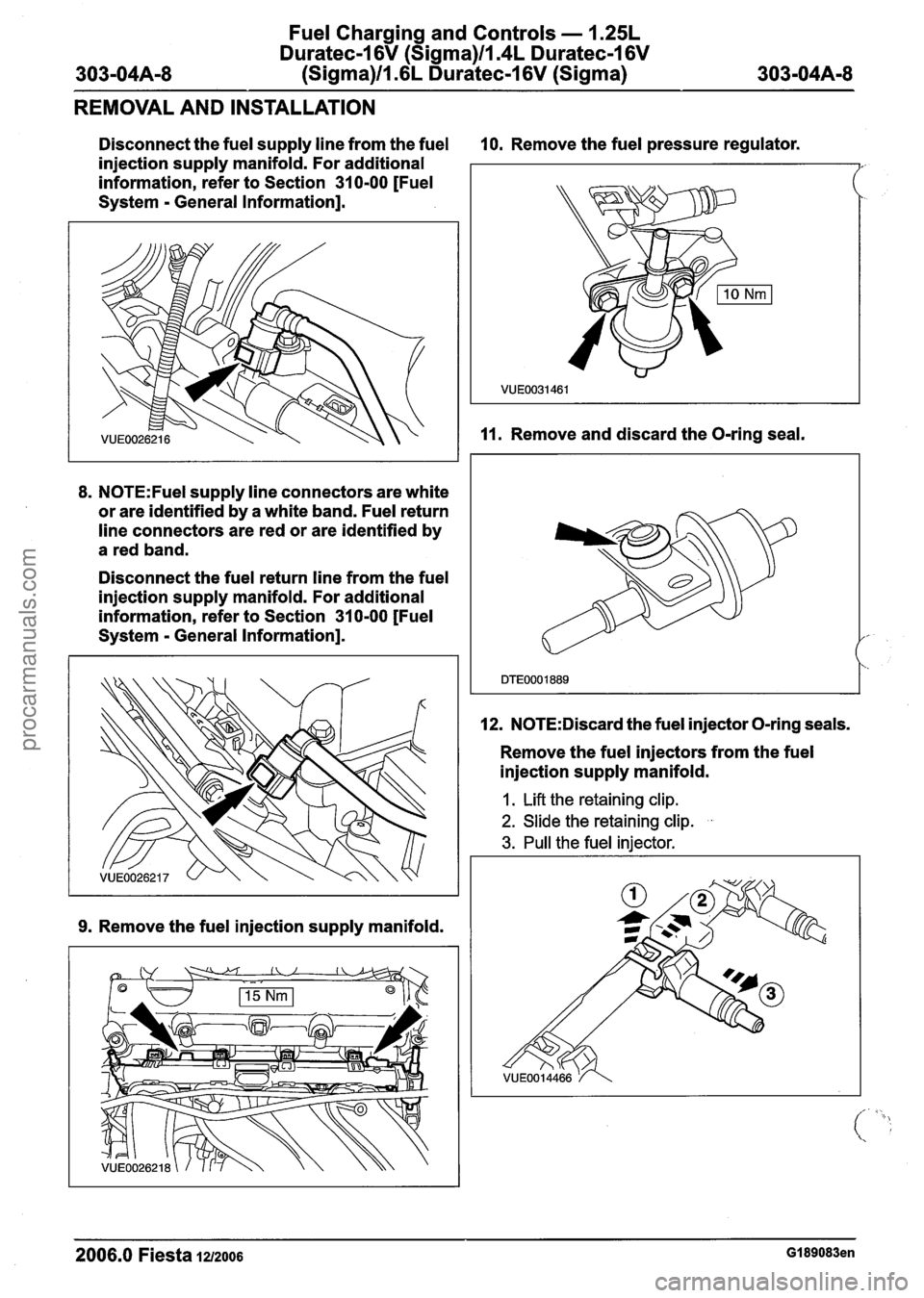
Disconnect the fuel supply line from the fuel 10. Remove the fuel pressure regulator.
injection supply manifold. For additional
information, refer to Section 31 0-00 [Fuel
System
- General Information].
8. N0TE:Fuel supply line connectors are white
or are identified by a white band. Fuel return
line connectors are red or are identified by
a red band.
Disconnect the fuel return line from the fuel
injection supply manifold. For additional
information, refer to Section 31 0-00 [Fuel
System
- General Information].
9. Remove the fuel injection supply manifold.
11. Remove and discard the O-ring seal.
12.
N0TE:Discard the fuel injector O-ring seals.
Remove the fuel injectors from the fuel
injection supply manifold.
1. Lift the retaining clip.
2. Slide the retaining clip. .
3. Pull the fuel injector.
2006.0 Fiesta 1212006 GI 89083en
procarmanuals.com