engine FORD FIESTA 2007 Service Manual
[x] Cancel search | Manufacturer: FORD, Model Year: 2007, Model line: FIESTA, Model: FORD FIESTA 2007Pages: 1226, PDF Size: 61.26 MB
Page 174 of 1226
206-00-2 Brake System - General Information 206-00-2
DESCRIPTION AND OPERATION
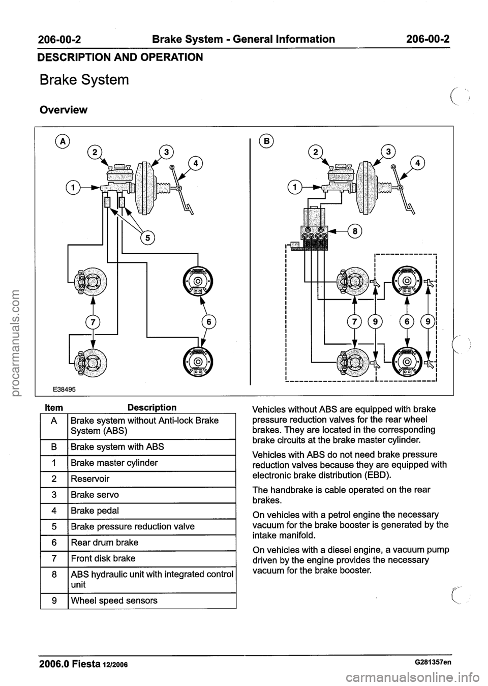
Brake System
Overview
A Brake system without Anti-lock
Brake
I I system (ABS)
I B I Brake system with ABS I
I 1 I Brake master cylinder I -
1 2 1 Reservoir I
1 4 1 Brake pedal I
1 5 1 Brake pressure reduction valve I
1 6 1 Rear drum brake I
171t disk brake I
8 ABS hydraulic unit with integrated control
1 1 unit
1 9 I Wheel speed sensors I
Vehicles without ABS are equipped with brake
pressure reduction valves for the rear wheel
brakes. They are located in the corresponding
brake circuits at the brake master cylinder.
Vehicles with ABS do not need brake pressure
reduction valves because they are equipped with
electronic brake distribution (EBD).
The handbrake is cable operated on the rear
brakes.
On vehicles with a petrol engine the necessary
vacuum for the brake booster is generated by the
intake manifold.
On vehicles with a diesel engine, a vacuum pump
driven by the engine provides the necessary
vacuum for the brake booster.
2006.0 Fiesta lu2006 G281357en
procarmanuals.com
Page 196 of 1226
206-00-24 Brake System - General Information 206-00-24
DIAGNOSIS AND TESTING
TEST CONDITIONS DETAILSIRESU LTSIACTIONS
12: ROAD TEST THE VEHICLE
rn Road test the vehicle and apply the brakes.
Are the brakes functioning correctly?
-+ Yes
Vehicle OK.
+ No
INSPECT individual wheel cylinders or
calipers for binding or sticking components.
INSTALL new components as necessary.
BLEED the brake system. REFER to: (206-00
Brake System
- General Information)
Brake System Bleeding (General Procedures),
Brake System Pressure Bleeding (General Procedures).
TEST the system for normal operation.
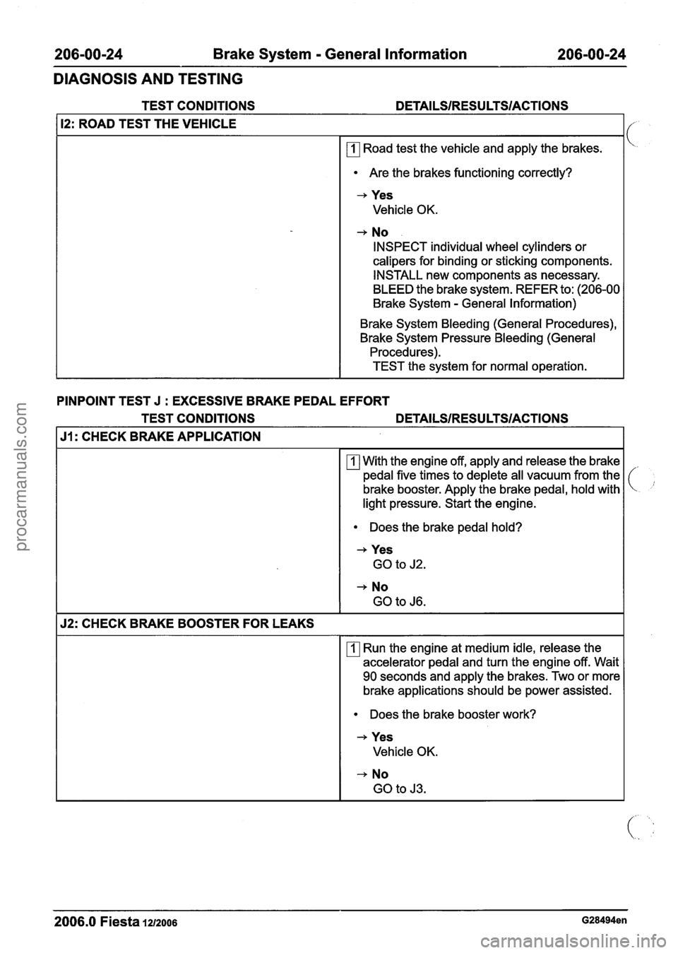
PINPOINT TEST J
: EXCESSIVE BRAKE PEDAL EFFORT
TEST CONDITIONS
DETAILSIRESULTSIACTIONS
J1: CHECK BRAKE APPLICATION
With the engine off, apply and release the brake
pedal five times to deplete all vacuum from the
brake booster. Apply the brake pedal, hold with
light pressure. Start the engine.
Does the brake pedal hold?
+ Yes
GO to J2.
+ No
GO to J6.
52: CHECK BRAKE BOOSTER FOR LEAKS
rn Run the engine at medium idle, release the
accelerator pedal and turn the engine off. Wait
90 seconds and apply the brakes. Two or more
brake applications should be power assisted.
Does the brake booster work?
+ Yes
Vehicle OK.
-+ No
GO to
J3.
2006.0 Fiesta 1212006 G28494en
procarmanuals.com
Page 197 of 1226
206-00-25 Brake System - General Information 206-00-25
DIAGNOSIS AND TESTING
TEST CONDITIONS
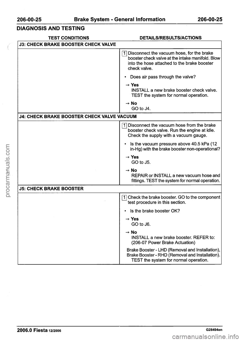
53: CHECK BRAKE BOOSTER CHECK VALVE
rn Disconnect the vacuum hose, for the brake
booster check valve at the intake manifold. Blow
into the hose attached to the brake booster
check valve.
Does air pass through the valve?
+ Yes
INSTALL a new brake booster check valve.
TEST the system for normal operation.
+ No
GO to J4.
54: CHECK BRAKE BOOSTER CHECK VALVE VACUUM
rn Disconnect the vacuum hose from the brake
booster check valve. Run the engine at idle.
Check the supply with a vacuum gauge.
Is the vacuum pressure above 40.5 kPa (12
in-Hg) with the brake booster non-operational?
+ Yes
GO to J5.
+ No
REPAIR or INSTALL a new vacuum hose and
fittings. TEST the system for normal operation.
55: CHECK BRAKE BOOSTER
rn Check the brake booster. GO to the component
test procedure in this section.
Is the brake booster OK?
+ Yes
GO to J6.
+ No
INSTALL a new brake booster. REFER to:
(206-07 Power Brake Actuation)
Brake Booster
- LHD (Removal and lnstallation),
Brake Booster
- RHD (Removal and lnstallation).
TEST the system for normal operation.
2006.0 Fiesta 1212006 G28494en
procarmanuals.com
Page 199 of 1226
206-00-27 Brake System - General Information 206-00-27
DIAGNOSIS AND TESTING
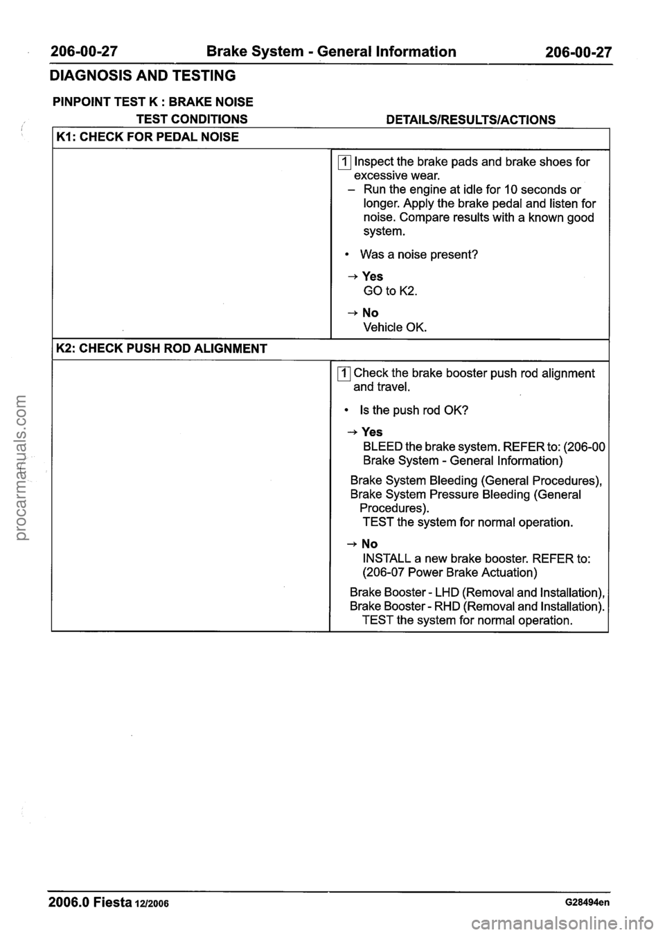
PINPOINT TEST K : BRAKE NOISE
TEST CONDITIONS
DETAILSIRESU LTSIACTIONS
K1: CHECK FOR PEDAL NOISE
Inspect the brake pads and brake shoes for
excessive wear.
- Run the engine at idle for 10 seconds or
longer. Apply the brake pedal and listen for
noise. Compare results with a known good
system.
Was a noise present?
-+ Yes
GO to K2.
-+ No
Vehicle OK.
K2: CHECK PUSH ROD ALIGNMENT
Check the brake booster push rod alignment
and travel.
Is the push rod OK?
-+ Yes
BLEED the brake system. REFER to: (206-00
Brake System
- General Information)
Brake System Bleeding (General Procedures),
Brake System Pressure Bleeding (General
Procedures). TEST the system for normal operation.
-+ No
INSTALL a new brake booster. REFER to:
(206-07 Power Brake Actuation)
Brake Booster
- LHD (Removal and lnstallation),
Brake Booster
- RHD (Removal and Installation).
TEST the system for normal operation.
2006.0 Fiesta 1212006 G28494en
procarmanuals.com
Page 200 of 1226
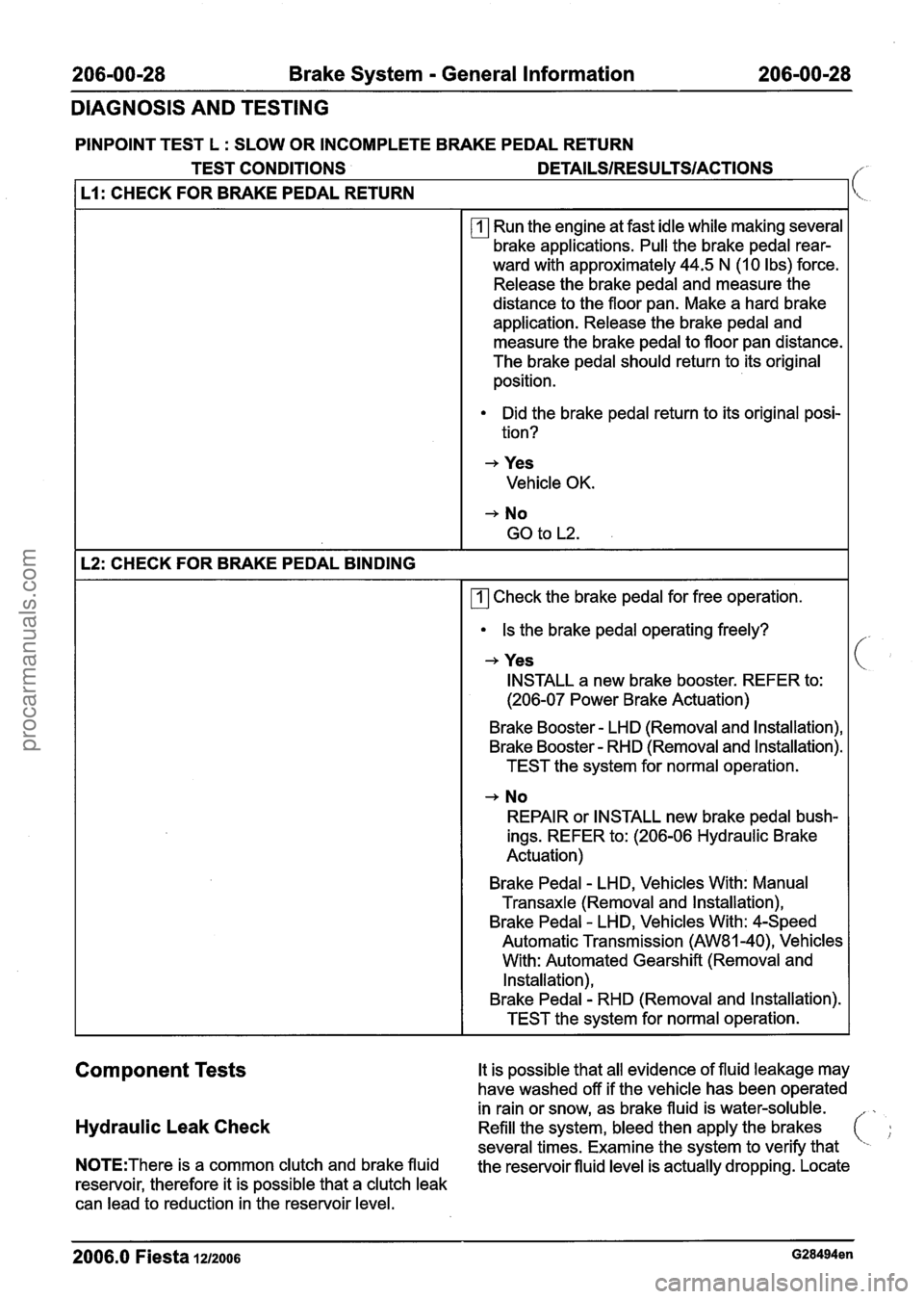
206-00-28 Brake System - General Information 206-00-28
DIAGNOSIS AND TESTING
PINPOINT TEST L : SLOW OR INCOMPLETE BRAKE PEDAL RETURN
TEST CONDITIONS
DETAILSIRESU LTSIACTIONS /"'
I L1: CHECK FOR BRAKE PEDAL RETURN I[<.
Run the engine at fast idle while making several
brake applications. Pull the brake pedal rear-
ward with approximately 44.5 N
(1 0 lbs) force.
Release the brake pedal and measure the
distance to the floor pan. Make a hard brake
application. Release the brake pedal and
measure the brake pedal to floor pan distance.
The brake pedal should return to its original
position.
Did the brake pedal return to its original posi-
tion?
+ Yes
Vehicle OK.
+ No
GO to L2.
I L2: CHECK FOR BRAKE PEDAL BINDING
1 171 Check the brake pedal for free operation.
I Is the brake pedal operating freely?
+ Yes
I INSTALL a new brake booster. REFER to:
(206-07 Power Brake Actuation)
Brake Booster
- LHD (Removal and lnstallation),
Brake Booster
- RHD (Removal and lnstallation).
TEST the system for normal operation.
+ No
REPAIR or INSTALL new brake pedal bush-
ings. REFER to: (206-06 Hydraulic Brake
Actuation)
Brake Pedal
- LHD, Vehicles With: Manual
Transaxle (Removal and lnstallation),
Brake Pedal
- LHD, Vehicles With: 4-Speed
Automatic Transmission
(AW81-40), Vehicles
With: Automated Gearshift (Removal and
Installation),
Brake Pedal
- RHD (Removal and lnstallation).
TEST the system for normal operation.
Component Tests It is possible that all evidence of fluid leakage may
have washed off if the vehicle has been operated
in rain or snow, as brake fluid is water-soluble.
Hydraulic Leak Check Refill the system, bleed then apply the brakes
several times. Examine the system to verify that
NOTE:Thet-e is a common clutch and brake fluid
the reservoir fluid level is actually dropping. Locate
reservoir, therefore it is possible that a clutch leak
can lead to reduction in the reservoir level.
-- --
2006.0 Fiesta 1212006 G28494en
procarmanuals.com
Page 201 of 1226

206-00-29 Brake System - General Information 206-00-29
DIAGNOSIS AND TESTING
and repair the external leak. If the fluid level drops
and no external leak can be found, check for a
brake master cylinder bore end seal leak.
Brake System Check
Brake Pedal Reserve Check
Where a low brake pedal or the feel of a
bottomed-out condition exists, check for brake
pedal reserve.
1. Operate the engine at idle with the transaxle in
NEUTRAL.
2. Apply the brake pedal lightly three or four times.
3. Allow 15 seconds for vacuum to replenish the
brake booster.
N0TE:This increased resistance may feel like
something has bottomed out.
4. Apply the brake pedal until it stops moving
downward or an increased resistance to the
pedal travel occurs.
5. Hold the brake pedal in the applied position and
raise the engine speed to approximately 2000
rpm.
N0TE:The additional movement of the brake pedal
is the result of the increased engine intake manifold
vacuum which exerts more force on the brake
booster during engine rundown. This means that
additional stroke is available in the brake master
cylinder and the brake system is not bottoming out.
6. Release the accelerator pedal and observe that
the brake pedal moves downward as the engine
returns to idle speed.
Brake Booster Functional Test
lnspect all hoses and connections. All unused
vacuum connectors should be capped. Hoses and
their connections should be correctly secured and
in good condition with no holes and no collapsed 2.
With the transaxle in NEUTRAL, stop the engine
and apply the parking brake. Apply the brake
pedal several times to exhaust all vacuum in
the system.
3. With the engine turned off and all vacuum in the
system exhausted, apply the brake pedal and hold it down. Start the engine. If the vacuum
system is operating, the brake pedal will tend
to move downward under constant foot
pressure. If no motion is felt, the vacuum
booster system is not functioning.
4. Remove the vacuum hose from the brake
booster.
Intake manifold vacuum should be
available at the brake booster end of the hose
with the engine at idle speed and the transaxle
in NEUTRAL. Make sure that all unused vacuum
outlets are correctly capped, hose connectors
are correctly secured and vacuum hoses are in
good condition. When it is established that
manifold vacuum is available to the brake
booster, connector the vacuum hose to the
brake booster and repeat Step
3. If no
downward movement of the brake pedal is felt,
install a new brake booster. REFER to: (206-07
Power Brake Actuation)
Brake Booster
- LHD (Removal and lnstallation),
Brake Booster
- RHD (Removal and lnstallation).
5. Operate the engine a minimum of 10 seconds
at fast idle. Stop the engine and let the vehicle
stand for
10 minutes. Then, apply the brake
pedal with approximately 89
N (20 lb) force. The
pedal feel (brake application) should be the
same as that noted with the engine operating.
If the brake pedal feels hard (no power assist),
install a new vacuum check valve and then
repeat the test. If the brake pedal still feels hard,
install a new brake booster. REFER to: (206-07
Power Brake Actuation)
Brake Booster
- LHD (Removal and Installation),
Brake Booster
- RHD e em oval and installation).
If the brake pedal movement feels spongy, bleed
the brake system. REFER to: (206-00 Brake
System
- General Information)
areas. Inspect the check valve on the brake booster Brake System Bleeding (General Procedures),
for damage. Brake
System Pressure Bleeding (General
Procedures).
Brake Booster Operation Check
Brake Master Cylinder
1. Check the hydraulic brake system for leaks or
low fluid. Usually,
the first and strongest indicator of anything
wrong with the braking system is a feeling through
the brake pedal. In diagnosing the condition of the
brake master cylinder, check pedal feel as
2006.0 Fiesta 1212006 G28494en I
i
procarmanuals.com
Page 282 of 1226
206-09A-8 Anti-Lock Control 206-09A-8
REMOVAL AND INSTALLATION
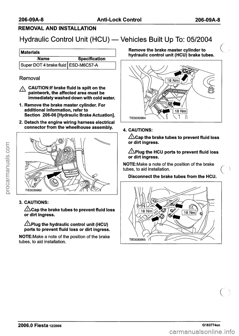
Hydraulic Control Unit (HCU) - Vehicles Built Up To: 0512004
!'-
Materials Remove
the brake master cylinder to
hydraulic control unit (HCU) brake tubes.
Name
S~ecification
I Super DOT 4 brake fluid I ESD-M6C57-A I
Removal
A CAUTI0N:If brake fluid is spilt on the
paintwork, the affected area must be
immediately washed down with cold water.
I. Remove the brake master cylinder. For
additional information, refer to
Section
206-06 [Hydraulic Brake Actuation].
2. Detach the engine wiring harness electrical
connector from the wheelhouse assembly.
3. CAUTIONS:
&ap the brake tubes to prevent fluid loss
or dirt ingress.
nplug the hydraulic control unit (HCU)
ports to prevent fluid loss or dirt ingress.
N0TE:Make a note of the position of the brake
tubes, to aid installation.
4. CAUTIONS:
&ap the braketubes to prevent fluid loss
or dirt ingress.
Aplug the HCU ports to prevent fluid loss
or dirt ingress.
N0TE:Make a note of the position of the brake
tubes, to aid installation.
Disconnect the brake tubes from the HCU.
2006.0 Fiesta 1212006 GI 83774en
procarmanuals.com
Page 285 of 1226
206-09A-1 I Anti-Lock Control 206-09A-I 1
REMOVAL AND INSTALLATION
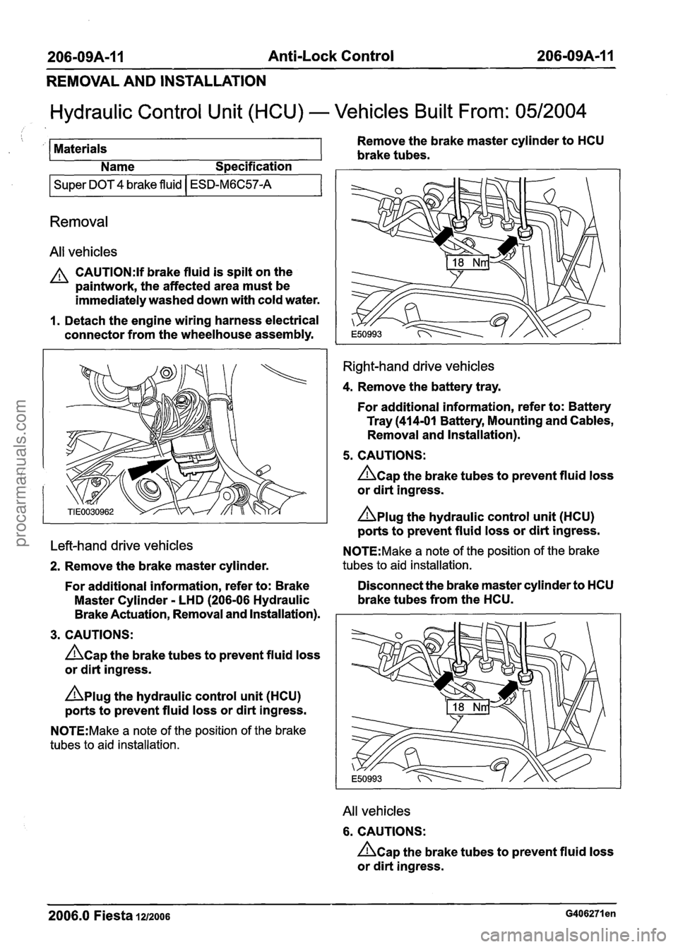
Hydraulic Control Unit (HCU) - Vehicles Built From: 0512004
/ ! Remove the brake master cylinder to HCU
Materials brake tubes.
Name Specification
I Super DOT 4 brake fluid I ESD-M6C57-A I
Removal
All vehicles
A CAUTI0N:If brake fluid is spilt on the
paintwork, the affected area must be
immediately washed down with cold water.
1. Detach the engine wiring harness electrical
connector from the wheelhouse assembly.
Right-hand drive vehicles
4. Remove the battery tray.
For additional information, refer to: Battery
Tray (414-01 Battery, Mounting and Cables,
Removal and Installation).
5. CAUTIONS:
hap the brake tubes to prevent fluid loss
or dirt ingress.
nplug the hydraulic control unit (HCU)
ports to prevent fluid loss or dirt ingress.
Left-hand drive vehicles N0TE:Make a note of the position of the brake
2. Remove the brake master cylinder. tubes to aid installation.
For additional information, refer to: Brake Disconnect
the brake master cylinder to HCU
Master Cylinder
- LHD (206-06 Hydraulic brake tubes
from the HCU.
Brake Actuation, Removal and Installation).
I
3. CAUTIONS: I
hap the brake tubes to prevent fluid loss
or dirt ingress.
nplug the hydraulic control unit (HCU)
ports to prevent fluid loss or dirt ingress.
N0TE:Make a note of the position of the brake
tubes to aid installation.
All vehicles
6. CAUTIONS:
&ap the brake tubes to prevent fluid loss
or dirt ingress.
2006.0 Fiesta 1212006 G406271 en
procarmanuals.com
Page 288 of 1226
206-09A-14 Anti-Lock Control 206-09A-I 4
REMOVAL AND INSTALLATION
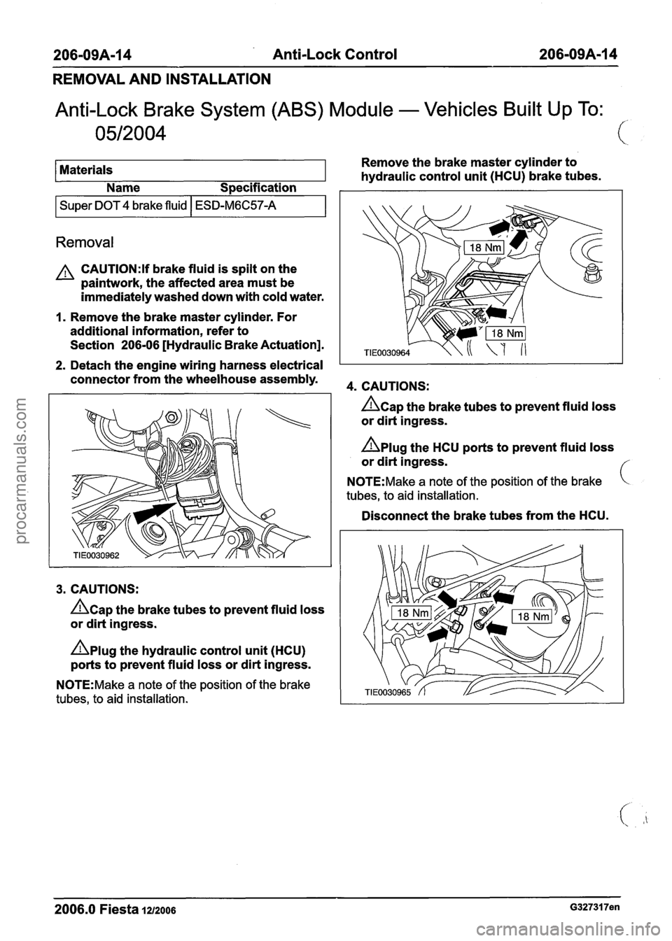
Anti-Lock Brake System (ABS) Module - Vehicles Built Up To: /.
Materials Remove
the brake master cylinder to
hydraulic control unit (HCU) brake tubes.
Name
S~ecification
I Super DOT 4 brake fluid 1 ESD-M6C57-A I
Removal
A CAUTI0N:Y brake fluid is spilt on the
paintwork, the affected area must be
immediately washed down with cold water.
1. Remove the brake master cylinder. For
additional information, refer to
Section
206-06 [Hydraulic Brake Actuation].
2. Detach the engine wiring harness electrical
connector from the wheelhouse assembly.
4m CAUTIONS:
3. CAUTIONS:
&ap the brake tubes to prevent fluid loss
or dirt ingress.
Aplug the hydraulic control unit (HCU)
ports to prevent fluid loss or dirt ingress.
N0TE:Make a note of the position of the brake
tubes, to aid installation.
&ap the brake tubes to prevent fluid loss
or dirt ingress.
Aplug the HCU ports to prevent fluid loss
or dirt ingress.
N0TE:Make a note of the position of the brake
tubes, to aid installation.
Disconnect the brake tubes from the HCU.
2006.0 Fiesta 1~12006 G327317en
procarmanuals.com
Page 291 of 1226
206-09A-I 7 Anti-Lock Control 206-09A-I 7
REMOVAL AND INSTALLATION
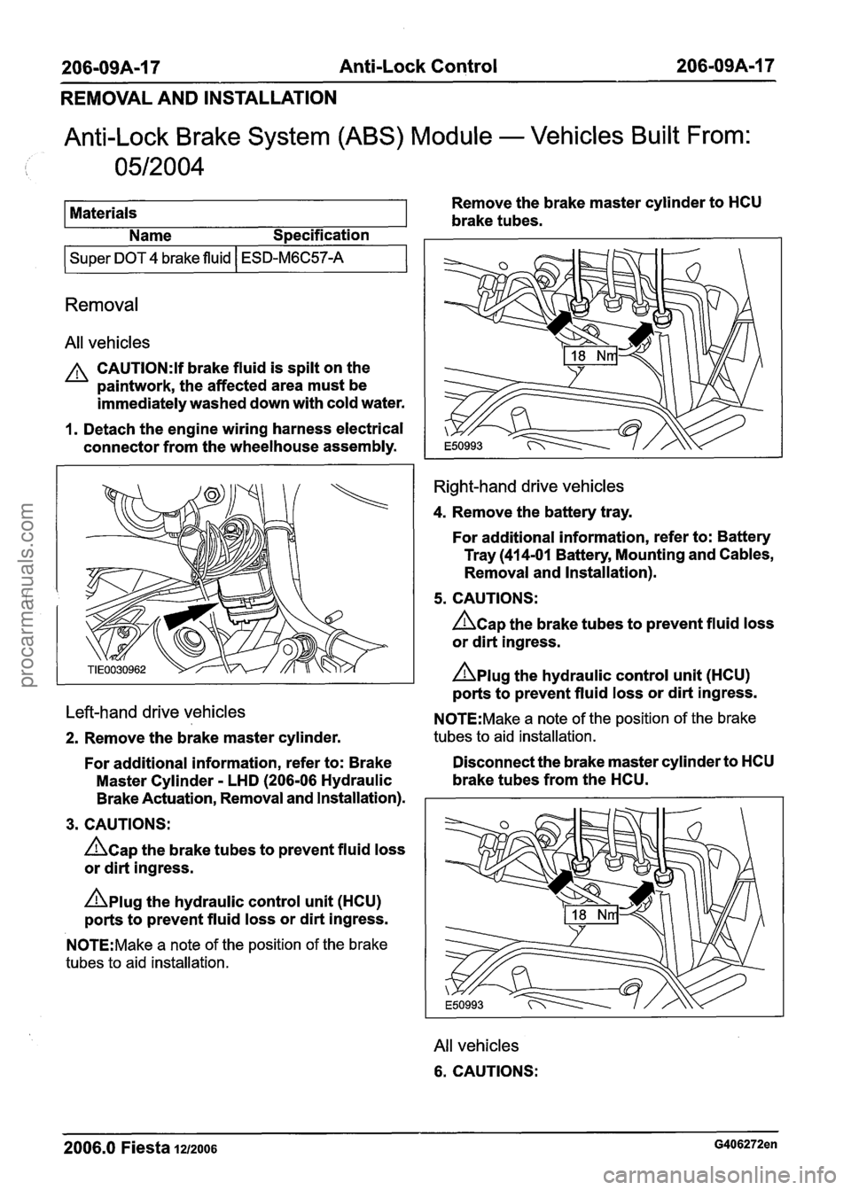
Anti-Lock Brake System (ABS) Module - Vehicles Built From:
0512004
Materials Remove
the brake master cylinder to HCU
brake tubes.
Name Specification
I Super DOT 4 brake fluid I ESD-M6C57-A I
Removal
All vehicles
A CAUTI0N:lf brake fluid is spilt on the
paintwork, the affected area must be
immediately washed down with cold water.
1. Detach the engine wiring harness electrical
connector from the wheelhouse assembly.
Left-hand drive vehicles
2. Remove the brake master cylinder.
For additional information, refer to: Brake
Master Cylinder
- LHD (206-06 Hydraulic
Brake Actuation, Removal and Installation).
3. CAUTIONS:
&ap the brake tubes to prevent fluid loss
or dirt ingress.
Aplug the hydraulic control unit (HCU)
ports to prevent fluid loss or dirt ingress.
N0TE:Make a note of the position of the brake
tubes to aid installation.
Right-hand drive vehicles
4. Remove the battery tray.
For additional information, refer to: Battery Tray (41 4-01 Battery, Mounting and Cables,
Removal and Installation).
5. CAUTIONS:
hap the brake tubes to prevent fluid loss
or dirt ingress.
nplug the hydraulic control unit (HCU)
ports to prevent fluid loss or dirt ingress.
N0TE:Make a note of the position of the brake
tubes to aid installation.
Disconnect the brake master cylinder to HCU
brake tubes from the HCU.
All vehicles
6. CAUTIONS:
2006.0 Fiesta 1212006 G406272en
procarmanuals.com