engine FORD FIESTA 2007 Repair Manual
[x] Cancel search | Manufacturer: FORD, Model Year: 2007, Model line: FIESTA, Model: FORD FIESTA 2007Pages: 1226, PDF Size: 61.26 MB
Page 310 of 1226
206-096-4 Anti-Lock Control - Stability Assist 206-096-4
REMOVAL AND INSTALLATION
Hydraulic Control Unit (HCU)
Materials Remove
the brake master cylinder to
hydraulic control unit (HCU) brake tubes.
Name Specification
I Super DOT4 brake fluid I ESD-M6C57-A 7
Removal
A CAUTI0N:lf brake fluid is spilt on the
paintwork, the affected area must be
immediately washed down with cold water.
1. Remove the brake master cylinder. For
additional information, refer to
Section
206-06 [Hydraulic Brake Actuation].
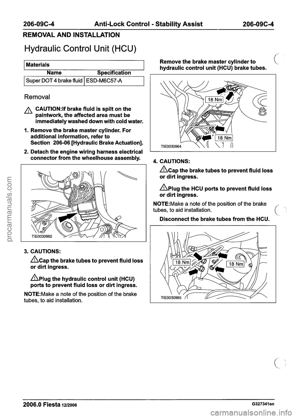
2. Detach the engine wiring harness electrical
connector from the wheelhouse assembly.
3. CAUTIONS:
hap the brake tubes to prevent fluid loss
or dirt ingress.
nplug the hydraulic control unit (HCU)
ports to prevent fluid loss or dirt ingress.
N0TE:Make a note of the position of the brake
tubes, to aid installation.
4. CAUTIONS:
&ap the brake tubes to prevent fluid loss
or dirt ingress.
Aplug the HCU ports to prevent fluid loss
or dirt ingress.
N0TE:Make a note of the position of the brake
tubes, to aid installation.
Disconnect the brake tubes from the HCU.
2006.0 Fiesta 1212006 ~327341 en
procarmanuals.com
Page 318 of 1226
206-09C-12 Anti-Lock Control - Stability Assist 206-096-1 2
REMOVAL AND INSTALLATION
Stability Assist Module ,/.. ,
Materials Remove
the brake master cylinder to
hydraulic control unit (HCU) brake tubes. C
Name Specification I I
I Super DOT 4 brake fluid I ESD-M6C57-A I
Removal
CAUTI0N:If brake fluid is spilt on the
paintwork, the affected area must be
immediately washed down with cold water.
I. Remove the brake master cylinder. For
additional information, refer to
Section
206-06 [Hydraulic Brake Actuation].
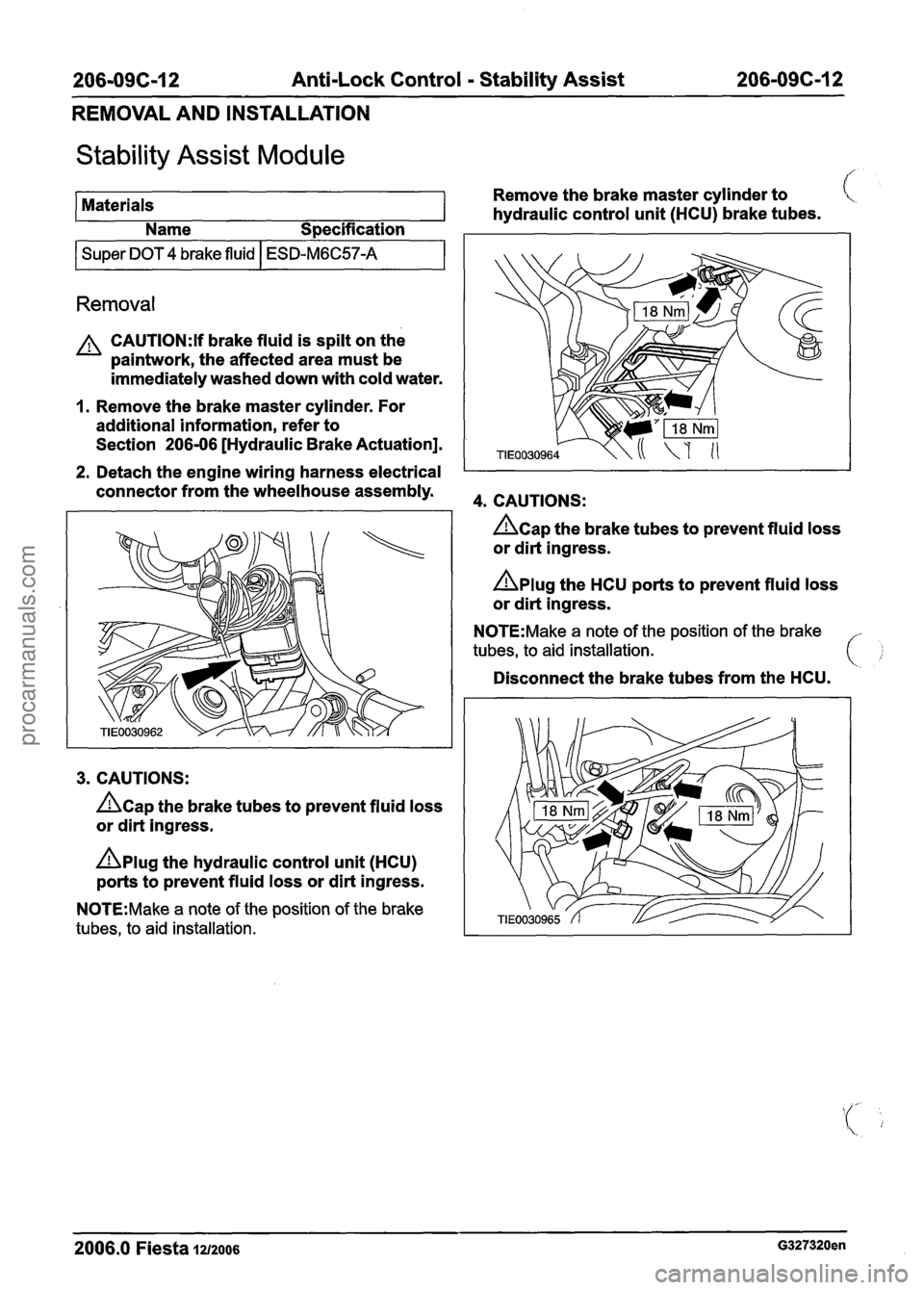
2. Detach the engine wiring harness electrical I
connector from the wheelhouse assembly. 4. CAUTIONS:
3. CAUTIONS:
hap the brake tubes to prevent fluid loss
or dirt ingress.
Dplug the hydraulic control unit (HCU)
ports to prevent fluid loss or dirt ingress.
N0TE:Make a note of the position of the brake
tubes, to aid installation.
hap the brake tubes to prevent fluid loss
or dirt ingress.
nplug the HCU ports to prevent fluid loss
or dirt ingress.
N0TE:Make a note of the position of the brake
tubes, to aid installation.
Disconnect the brake tubes from the HCU.
2006.0 Fiesta 1~12006 G327320en
procarmanuals.com
Page 324 of 1226
21 1-00-4 Steering System - General Information 21 1-00-4
DESCRIPTION AND OPERATION
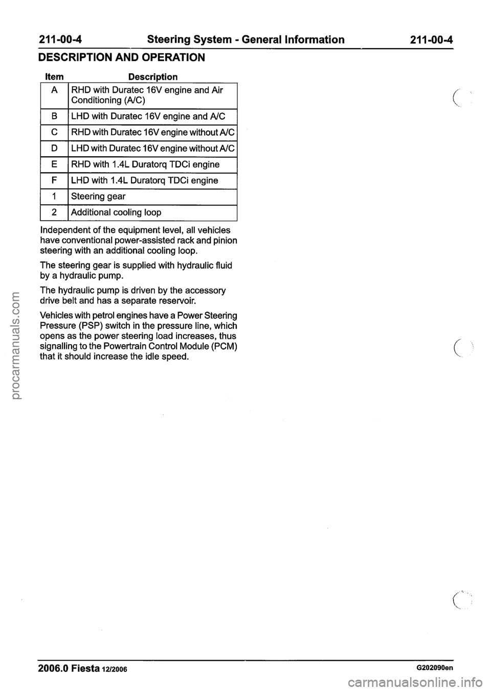
Item Descri~tion
A
RHD with Duratec 16V engine and Air
1 I Conditioning (NC)
I B I LHD with Duratec 16V engine and NC I
I C I RHD with Duratec 16V engine without AM: I
I D I LHD with Duratec 16V engine without NC I
I E ( RHD with 1.4L Duratorq TDCi engine I
I F I LHD with 1.4L Duratorq TDCi engine I
I I I Steering gear I
1 2 1 Additional cooling loop I
Independent of the equipment level, all vehicles
have conventional power-assisted rack and pinion
steering with an additional cooling loop.
The steering gear is supplied with hydraulic fluid
by a hydraulic pump.
The hydraulic pump is driven by the accessory
drive belt and has a separate reservoir.
Vehicles with petrol engines have a Power Steering
Pressure (PSP) switch in the pressure line, which
opens as the power steering load increases, thus
signalling to the Powertrain Control Module (PCM)
that it should increase the idle speed.
- - -- - -
2006.0 Fiesta 1212006 G202090en
procarmanuals.com
Page 325 of 1226
211 -00-5 Steering System - General Information 211 -00-5
DIAGNOSIS AND TESTING
Steering System
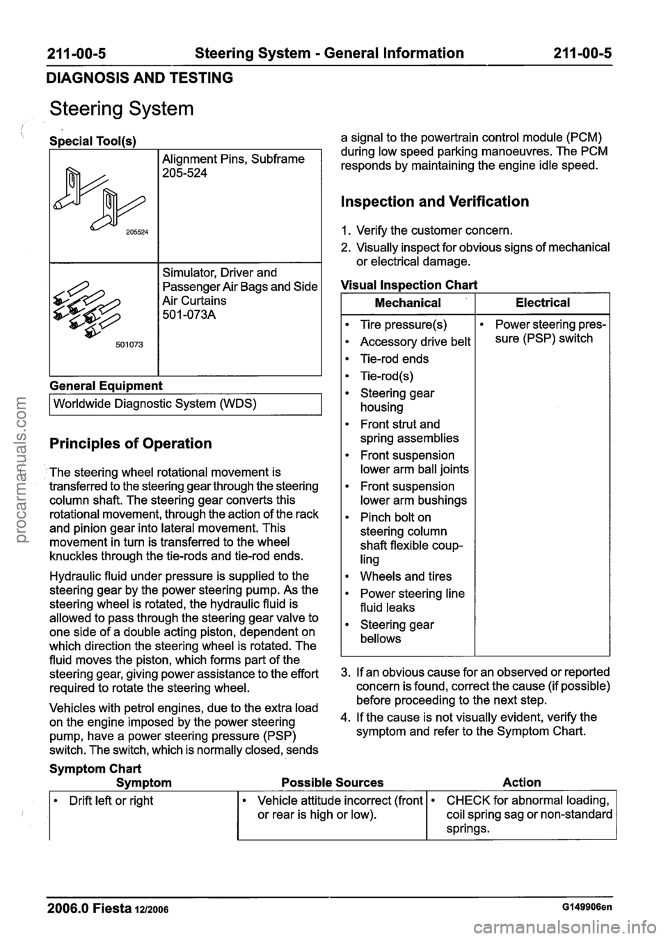
/ Special Tool(s)
Alignment Pins, Subframe
205-524
Simulator, Driver and
passenger ~ir Bags and Side
Air Curtains 50
1 -073A
General Eaui~ment
I Worldwide Diagnostic System (WDS) I
Principles of Operation
The steering wheel rotational movement is
transferred to the steering gear through the steering
column shaft. The steering gear converts this
rotational movement, through the action of the rack
and pinion gear into lateral movement. This
movement in turn is transferred to the wheel
knuckles through the tie-rods and tie-rod ends.
Hydraulic fluid under pressure is supplied to the
steering gear by the power steering pump. As the
steering wheel is rotated, the hydraulic fluid is
allowed to pass through the steering gear valve to
one side of a double acting piston, dependent on
which direction the steering wheel is rotated. The
fluid moves the piston, which forms part of the
steering gear, giving power assistance to the effort
required to rotate the steering wheel.
Vehicles with petrol engines, due to the extra load
on the engine imposed by the power steering
pump, have a power steering pressure (PSP)
switch. The switch, which is normally closed, sends a signal
to the powertrain control module (PCM)
during low speed parking manoeuvres. The PCM
responds by maintaining the engine idle speed.
lnspection and Verification
1. Verify the customer concern.
2. Visually inspect for obvious signs of mechanical
or electrical damage.
Visual lnspection Chart
I Mechanical I Electrical I
Tire pressure(s)
Accessory drive belt
Tie-rod ends
Tie-rod (s)
Steering gear housing
Front strut and
spring assemblies
Front suspension
lower arm ball joints
Front suspension
lower arm bushings
Pinch bolt on
steering column
shaft flexible coup-
ling Power
steering pres-
sure (PSP) switch
Wheels and tires
Power steering line
fluid leaks
Steering gear
bellows
3. If an obvious cause for an observed or reported
concern is found, correct the cause (if possible)
before proceeding to the next step.
4. If the cause is not visually evident, verify the
symptom and refer to the Symptom Chart.
Symptom Chart
Symptom Possible Sources Action
Drift left or right
2006.0 Fiesta 1212006 Gl49906en
Vehicle attitude incorrect (front
or rear is high or low). CHECK for abnormal loading,
coil spring sag or non-standard
springs.
procarmanuals.com
Page 334 of 1226

211 -00-14 Steering System - General Information 21 1-00-1 4
DIAGNOSIS AND TESTING
Symptom
Engine stalls when parking with
engine speed at idle Possible
Sources Action
I Worn front suspension lower 1. CARRY OUT the suspension f-
ball joint inspection component'
test.
REFER to: Suspension System
(204-00 Suspension System
- General Information,
Diagnosis and Testing).
Steering gear bushings worn
or perished. CHECK
and INSTALL new
components as necessary.
REFER to: Steering Gear
Bushing (21 1-02 Power
Steering, Removal and
Installation).
Loose steering gear retaining
bolts. CHECK and INSTALL new
steering gear retaining bolts as
necessary.
REFER to: Specifications (21 1
-
02 Power Steering, specifica-
tions).
Loose steering column retaining bolts.
CHECK and INSTALL new
steering column retaining bolts as necessary.
REFER to: Specifications (21 1
-
04 Steering Column,
Specifications).
Loose steering column to
steering gear pinion retaining bolt. CHECK
and INSTALL a new
steering column to steering
gear pinion retaining bolt as
necessary.
REFER to: Specifications (21 1
-
02 Power Steering, specifica-
tions).
I Excessive steering gear back-
lash. CARRY
OUT the steering
linkage component test.
REFER to Steering Linkage
Component Test in this
procedure.
Power steering pressure (PSP)
or additional information, refer
switch or circuit.
1. I to WDS.
Components Tests
Steering Linkage
column bearing wear, steering column universal
joint free play, steering wheel or steering column
looseness. The steering column cannot be
repaired. Install a new steering column.
('- .,
1. Grasp the steering wheel firmly and move it up REFER to: Steering Column
(21 1-04 Steering "'
and down and to the left and right without Column, Removal and Installation).
turning the steering wheel, to check for steering
2006.0 Fiesta 1212006 Gl49906en
procarmanuals.com
Page 336 of 1226
21 1-00-1 6 Steering System - General Information 21 I -00-1 6
DIAGNOSIS AND TESTING
8m ACAUTION:T~ prevent damage to the
steering linkage, turn the steering wheel to
move the steering linkage to the steering
lock stop.
Turn the steering wheel to position the steering
linkage against the left-hand steering lock stop.
9. N0TE:To isolate the steering gear design
'clearance, check the left-hand
tiemrod with
the steering held against the left-hand
steering lock stop.
With the aid of another technician holding the
steering against the left-hand steering lock stop,
firmly grasp the left-hand road wheel and apply
a rocking motion to check for any free play in
the tie-rod.
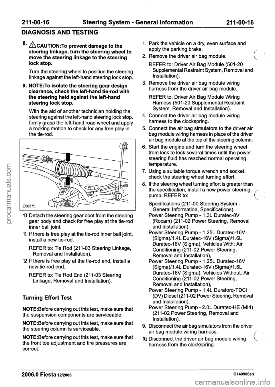
IQ Detach the steering gear boot from the steering
gear body and check for free play at the tie-rod
inner ball joint.
11. If there is free play at the tie-rod inner ball joint,
install a new tie-rod.
REFER to: Tie Rod (211-03 Steering Linkage,
Removal and lnstallation).
I2 If there is free play at the tie-rod end, install a
new tie-rod end.
REFER to: Tie Rod End (21 1-03 Steering
Linkage, Removal and lnstallation).
Turning Effort Test
N0TE:Before carrying out this test, make sure that
the suspension components are serviceable.
N0TE:Before carrying out this test, make sure that
the steering column is serviceable.
N0TE:Before carrying out this test, make sure that
the front toe adjustment and tire pressures are
correct. 1.
Park the vehicle on a dry, even surface and
apply the parking brake.
/- ,
2. Remove the driver air bag module.
REFER to: Driver Air Bag Module (501 -20
Supplemental Restraint System, Removal and
Installation).
3. Remove the driver air bag module wiring
harness from the driver air bag module.
REFER to: Driver Air Bag Module Wiring
Harness (501 -20 Supplemental Restraint
System, Removal and Installation).
4. Connect the driver air bag module wiring
harness to the clockspring.
5. Connect the air bag simulators to the driver air
bag module wiring harness in place of the driver
air bag module at the top of the steering column.
6. Start the engine and turn the steering wheel
from lock to lock several times until the power
steering fluid has reached normal operating
temperature.
7. Using a suitable torque wrench and socket,
check the steering wheel turning effort.
8. If the steering wheel turning effort is greater than
the specification, install a new power steering -
pump. REFER to: i
Specifications (21 1-00 Steering System -
General Information, Specifications),
Power Steering Pump
- I .3L Duratec-8V
(Rocam) (21 1-02 Power Steering, Removal
and lnstallation),
Power Steering Pump
- 1.25L Duratec-1 6V
(Sigma)/l.4L Duratec-1 6V (Sigma)/l .6L
Duratec-l6V (Sigma), Vehicles With: Air
Conditioning (21 1-02 Power Steering,
Removal and lnstallation),
Power Steering Pump
- I .25L Duratec-I 6V
(Sigma)/l.4L Duratec-1 6V (Sigma)/l .6L
Duratec-I 6V (Sigma), Vehicles Without: Air
Conditioning (21 1-02 Power Steering, Removal and lnstallation),
Power Steering Pump
- 1.4L Duratorq-TDCi
(DV) Diesel (21 1-02 Power Steering, Removal
and lnstallation),
Power Steering Pump
- 2.OL Duratec-HE (M14)
(21 1-02 Power Steering, Removal and
Installation).
Disconnect the air bag simulators from the driver
air bag module wiring harness.
//
IQ Disconnect the driver air bag module wiring i,,.
harness from the clockspring.
2006.0 Fiesta 1212006 GI 49906en
procarmanuals.com
Page 338 of 1226
211 -00-1 8 Steering System - General Information 211 -00-1 8
DIAGNOSIS AND TESTING
Steering Gear Checks After a Collision
f
system REFER to: Steering Gear (211-02 Power
The following list of steering gear conditions and
Steering, Removal and Installation).
the methods
of testing should be taken into ~CCOU~~ 2. Check the tightening torque of the tiemrod end when carrying out checks to the steering system:
to wheel knuckle nut.
General
Equipment TIE-RODS (.
If
the steering gear has no faults after
REFER to: Tie Rod End (21 1-03 Steering
completing the following checks, do not install
Linkage, Removal and Installation).
a new steering gear.
3. Check the tightening torque of the tie-rod end
Surface corrosion and marks on the tie-rod are
locking nut.
acceptable.
When checking for turning effort torque peaks REFER to: Tie
Rod End
(211-03 Steering
in the steering gear, turn the steering wheel from Linkage,
Removal and lnstallation).
Feeler gauge
Straight edge
steering lock-stop to steering lock
stop in CHECK FOR TURNING EFFORT TORQUE
approximately 15 seconds. PEAKS
IN THE STEERING GEAR
1.
Using a straight edge and feeler gauge, check
the tie-rods to see if they are straight. If the
distance between the tie-rod and straight edge
A steady increase of turning effort torque from
steering center to steering lock stop is
acceptable.
When checking for power steering fluid leaks,
turn the steering wheel to the steering lock stop
in approximately
10 seconds.
Noises from the power steering, for example
the power steering pump relief valve, are
acceptable. is
greater than 0.5 mm, install a new steering
Items to be observed when checking the steering gear.
STEERING GEAR HOUSING
I. Raise and support the vehicle.
REFER to: Lifting
(1 00-02 Jacking and Lifting,
Description and Operation).
2. Visually inspect the steering gear housing for
cracks and damage. If the steering gear housing
is cracked or damaged, install a new steering
gear.
REFER to: Steering Gear
(21 1-02 Power
Steering, Removal and lnstallation).
1. Lower and support the vehicle making sure that
the road wheels are just clear of the floor.
2. With the ignition switch in position
I, slowly turn
the steering wheel from steering lock stop to
steering lock stop. If a turning effort torque peak
or judder is felt while turning the steering wheel,
detach the tie-rods from the wheel knuckles.
3. Slowly turn the steering wheel from steering
lock stop to steering lock stop. If a turning effort
torque peak or judder is felt while turning the
steering wheel, install a new steering gear.
REFER to: Steering Gear
(211-02 Power
Steering, Removal and lnstallation).
CHECK FOR POWER STEERING FLUID LEAKS
1. Lower the vehicle.
2. Run the engine at a fast idle and slowly turn the
steering wheel to the left-hand steering lock
stop. Hold the steering wheel in this position for
5 seconds with a turning effort torque of
15 Nm
at the steering wheel rim.
3. Turn the steering wheel away from the left-hand
steering lock stop for 30 seconds.
4. Run the engine at a fast idle and slowly turn the
steering wheel to the right-hand steering lock
stop. Hold the steering wheel in this position for
5 seconds with a turning effort torque of
15 Nm '
at the steering wheel rim. (\,
2006.0 Fiesta 1212006 ~538091 en
procarmanuals.com
Page 340 of 1226
21 1 -00-20 Steering System - General Information 21 1-00-20
GENERAL PROCEDURES
Power Steering System Filling(l3 002 0)
Special Tool(s)
Adapter, Power Steering
Bleeding
211-189 (13-016)
I ( Hand Vacuum
Refill
"%s a3
1. N0TE:When filling the power steering fluid
reservoir, make sure that the power steering
fluid is clean and not agitated prior to use.
The power steering fluid should be poured
slowly into the reservoir to minimize the
possibility of aeration. The power steering
fluid level should be checked with the power
steering fluid cold.
PumpIPressure Pump
41 6-DO01 (23-036A)
Fill the power steering fluid reservoir to the
MAX mark with the appropriate power
steering fluid.
For additional information, refer to:
Specifications (211-00 Steering System
-
General Information, Specifications).
2. Raise and support the vehicle making sure
that the road wheels are just clear of the
floor. For additional information, refer to:
(1 00-02 Jacking and Lifting)
Jacking (Description and Operation),
Lifting (Description and Operation).
3.
N0TE:Do not start the engine at this stage.
N0TE:Make sure that the power steering fluid in
the power steering fluid reservoir does not fall
below the MIN mark,
as air could enter the system.
Slowly turn the steering wheel from lock to
lock and add power steering fluid until the
power steering fluid in the power steering
fluid reservoir stops dropping. 4.
N0TE:Make sure that
the power steering fluid \.
in the power steering fluid reservoir does
not fall below the MIN mark, as air could
enter the system.
Start the engine and slowly turn the steering
wheel from lock to lock and add power
steering fluid until the power steering fluid
in the power steering fluid reservoir stops
dropping.
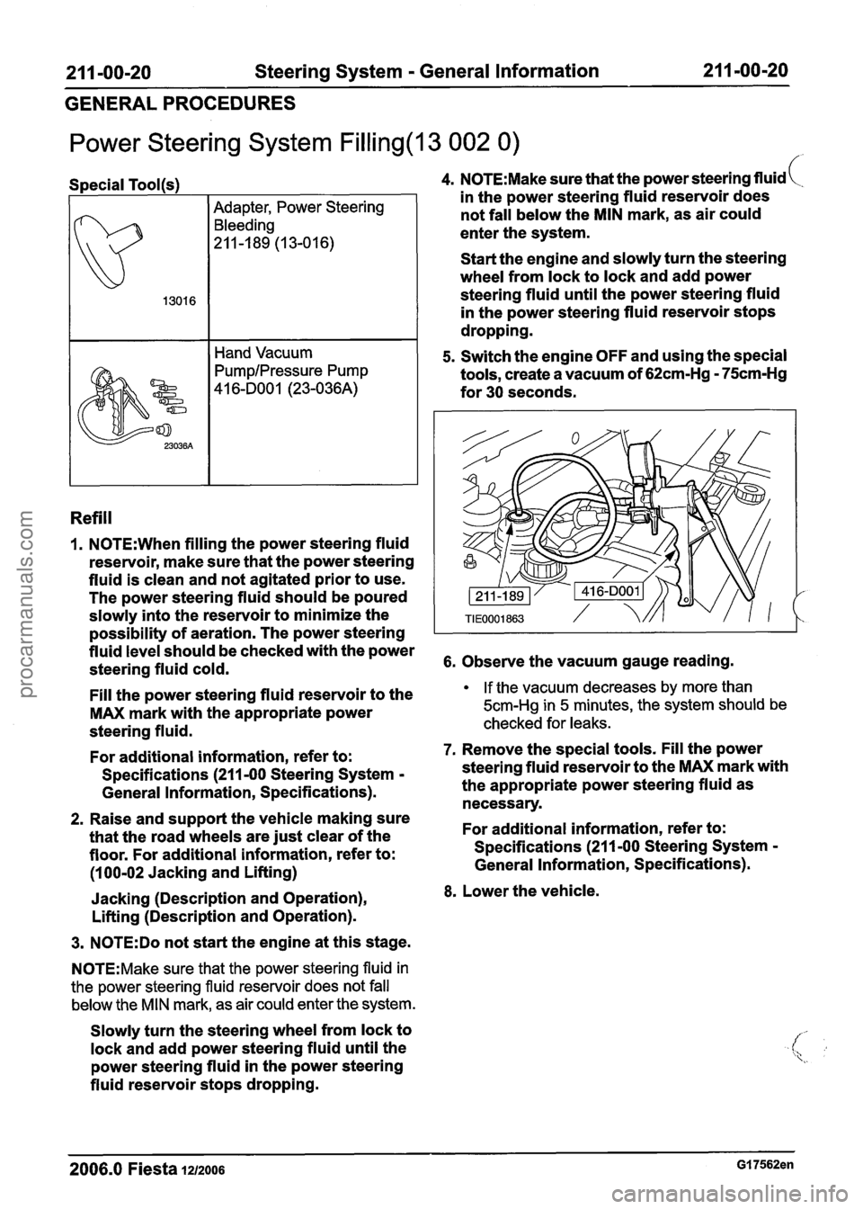
5. Switch the engine OFF and using the special
tools, create a vacuum of
62cm-Hg - 75cm-Hg
for 30 seconds.
6. Observe the vacuum gauge reading.
If the vacuum decreases by more than
5cm-Hg
in 5 minutes, the system should be
checked for leaks.
7. Remove the special tools. Fill the power
steering fluid reservoir to the
MAX mark with
the appropriate power steering fluid as
necessary.
For additional information, refer to:
Specifications (211 -00 Steering System
-
General Information, Specifications).
8. Lower the vehicle.
2006.0 Fiesta 1212006 GI 7562en
procarmanuals.com
Page 341 of 1226
211 -00-21 Steering System - General Information 211 -00-21
GENERAL PROCEDURES
Power Steering System Bleeding(l3 41 6 I )
Adapter, Power Steering
Bleeding
211-189 (13-016)
I I Hand Vacuum
PumpIPressure Pump
41 6-DO01 (23-036A)
Bleeding
1. N0TE:When filling the power steering fluid
reservoir, make sure that the power steering
fluid is clean and not agitated prior to use.
The power steering fluid should be poured , slowly into the reservoir to minimize the
possibility of aeration. The power steering
fluid level should be checked with the power
steering fluid cold.
Fill the power steering fluid reservoir to the
MAX mark with the appropriate power
steering fluid.
For additional information, refer to:
Specifications (211-00 Steering System
-
General Information, Specifications).
2. Raise and support the vehicle making sure
that the road wheels are just clear of the
floor. For additional information, refer to:
(1 00-02 Jacking and Lifting)
Jacking (Description and Operation),
Lifting (Description and Operation).
3. N0TE:Do not start the engine at this stage.
N0TE:Make sure that the power steering fluid in
the power steering fluid reservoir does not fall
below the MIN mark, as air could enter the system.
Slowly turn the steering wheel from lock to
lock and add power steering fluid until the
power steering fluid in the power steering
fluid reservoir stops dropping.
4. Check the power steering fluid level. Fill the
power steering fluid reservoir to the MAX
mark with the appropriate power steering
fluid.
For additional information, refer to:
Specifications (211 -00 Steering System
-
General Information, Specifications).
5.
N0TE:When bleeding the power steering
system the vacuum will decrease. Using the
special tools, maintain a sufficient vacuum
of
38cm-Hg. If the vacuum decreases by
more than
5cm-Hg in 5 minutes, the system
should be checked for leaks.
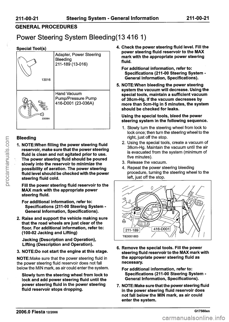
Using the special tools, bleed the power
steering system in the following sequence.
1. Slowly turn the steering wheel from lock to
lock once; then turn the steering wheel to the
right, just off the stop.
2. Using the special tools, create a vacuum of
38cm-Hg. Maintain the vacuum until the air
is evacuated from the system (minimum of
five minutes).
3. Release the vacuum.
4. Repeat the power steering bleeding
procedure, turning the steering wheel to the
left, just off the stop.
6. Remove the special tools. Fill the power
steering fluid reservoir to the MAX mark with
the appropriate power steering fluid as
necessary.
For additional information, refer to:
Specifications (21 1-00 Steering System
-
General Information, Specifications).
7. N0TE:Make sure that the power steering fluid
in the power steering fluid reservoir does
not fall below the MIN mark, as air could
enter the system.
2006.0 Fiesta 1212006 GI 7560en
procarmanuals.com
Page 342 of 1226
21 1-00-22 Steering System - General Information 21 1-00-22
GENERAL PROCEDURES
Start the engine and slowly turn the steering
wheel from lock to lock and add power
steering fluid until the power steering fluid
in the power steering fluid reservoir does
not drop.
8. Switch OFF the engine and examine the
power steering hose connections, steering
gear boots, power steering valve body and
power steering pump for external leaks.
9. Check the power steering fluid level. Fill the
power steering fluid reservoir to the MAX
mark with the appropriate power steering
fluid.
For additional information, refer to:
Specifications (211
-00 Steering System -
General Information, Specifications).
10.
N0TE:When bleeding the power steering
system the vacuum will decrease. Using
the special tools, maintain a sufficient
vacuum of
38cm-Hg. If the vacuum
decreases by more than
5cm-Hg in 5
minutes, the system should be checked for
leaks.
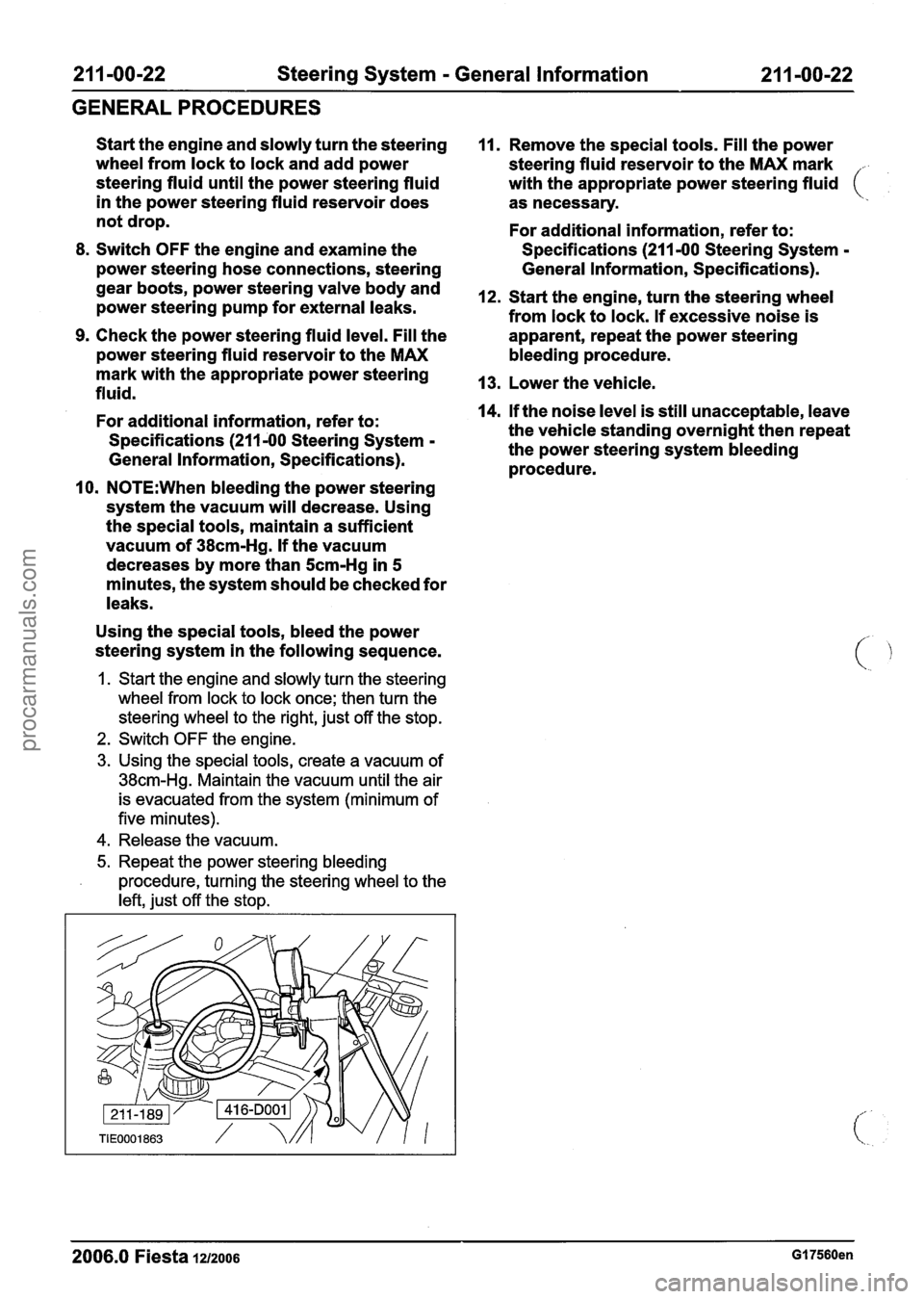
Using the special tools, bleed the power
steering system in the following sequence.
1. Start the engine and slowly turn the steering
wheel from lock to lock once; then turn the
steering wheel to the right, just off the stop.
2. Switch OFF the engine.
3. Using the special tools, create a vacuum of
38cm-Hg. Maintain the vacuum until the air
is evacuated from the system (minimum of
five minutes).
4. Release the vacuum.
5. Repeat the power steering bleeding
procedure, turning the steering wheel to the
left, just off the stop.
11. Remove the special tools. Fill the power
steering fluid reservoir to the MAX mark
.
with the appropriate power steering fluid (
as necessary.
For additional information, refer to:
Specifications (211
-00 Steering System -
General Information, Specifications).
12. Start the engine, turn the steering wheel
from lock to lock. If excessive noise is
apparent, repeat the power steering
bleeding procedure.
13. Lower the vehicle.
14.
If the noise level is still unacceptable, leave
the vehicle standing overnight then repeat
the power steering system bleeding
procedure.
- -
2006.0 Fiesta 121zo06 GI 7560en
procarmanuals.com