FORD FIESTA 2007 Workshop Manual
Manufacturer: FORD, Model Year: 2007, Model line: FIESTA, Model: FORD FIESTA 2007Pages: 1226, PDF Size: 61.26 MB
Page 491 of 1226
Engine - 1.25L Duratec-1 6V (Sigma)ll.4L
303-01 A-I 5 Duratec-1 6V (Sigma)/l.GL Duratec-1 6V (Sigma) 303-01A-I 5
IN-VEHICLE REPAIR
4. Install the timing belt.
1 For additional information, refer to: Timing I Belt (303-01 Engine - I .25L Duratec-1 6V
(Sigma)ll.4L Duratec-1 6V (Sigma)ll .6L
Duratec-1 6V (Sigma), Invehicle Repair).
2006.0 Fiesta 1212006 G21046en
procarmanuals.com
Page 492 of 1226
Engine - 1.25L Duratec-1 6V (Sigma)ll.4L
303-OIA-I 6 Duratec-1 6V (Sigma)ll .6L Duratec-1 6V (Sigma) 303-OIA-I 6
IN-VEHICLE REPAIR
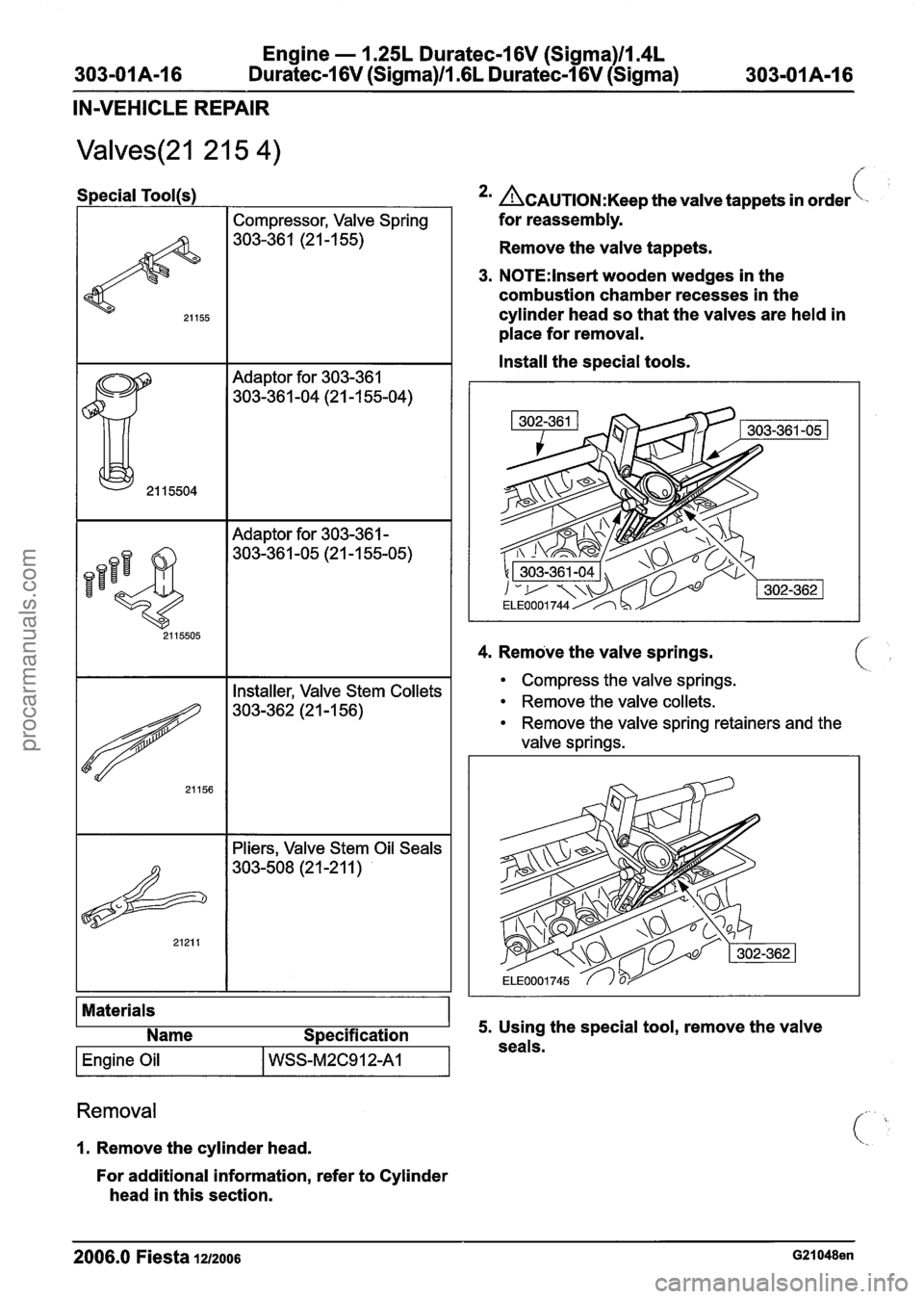
Special Tool(s1
Compressor, Valve Spring
303-36 1 (2 1
-1 55)
Adaptor for 303-361
303-36 1 -04 (2 1 -1 55-04)
I I Adaptor for 303-361 - I
4. Remove the valve springs.
Materials Name Specification
I Engine Oil I WSS-M2C912A1 I
*' ~CAUTION:K~~~ the valve tappets in order\-
for reassembly.
Remove the valve tappets.
3. N0TE:lnset-t wooden wedges in the
combustion chamber recesses in the
cylinder head so that the valves are held in
place for removal.
Install the special tools.
I I Installer, Valve Stem Collets I
I I Pliers, Valve Stem Oil Seals I
Removal
1. Remove the cylinder head.
For additional information, refer to Cylinder
head in this section.
Compress the valve springs.
Remove the valve collets.
Remove the valve spring retainers and the
valve springs.
5. Using the special tool, remove the valve
seals.
2006.0 Fiesta 1212006 G21048en
procarmanuals.com
Page 493 of 1226
Engine - 1.25L Duratec-1 6V (Sigma)ll.4L
-01A-17 Duratec-1 6V (Sigma)/l.GL Duratec-1 6V (Sigma) 303-OIA-1 7
IN-VEHICLE REPAIR
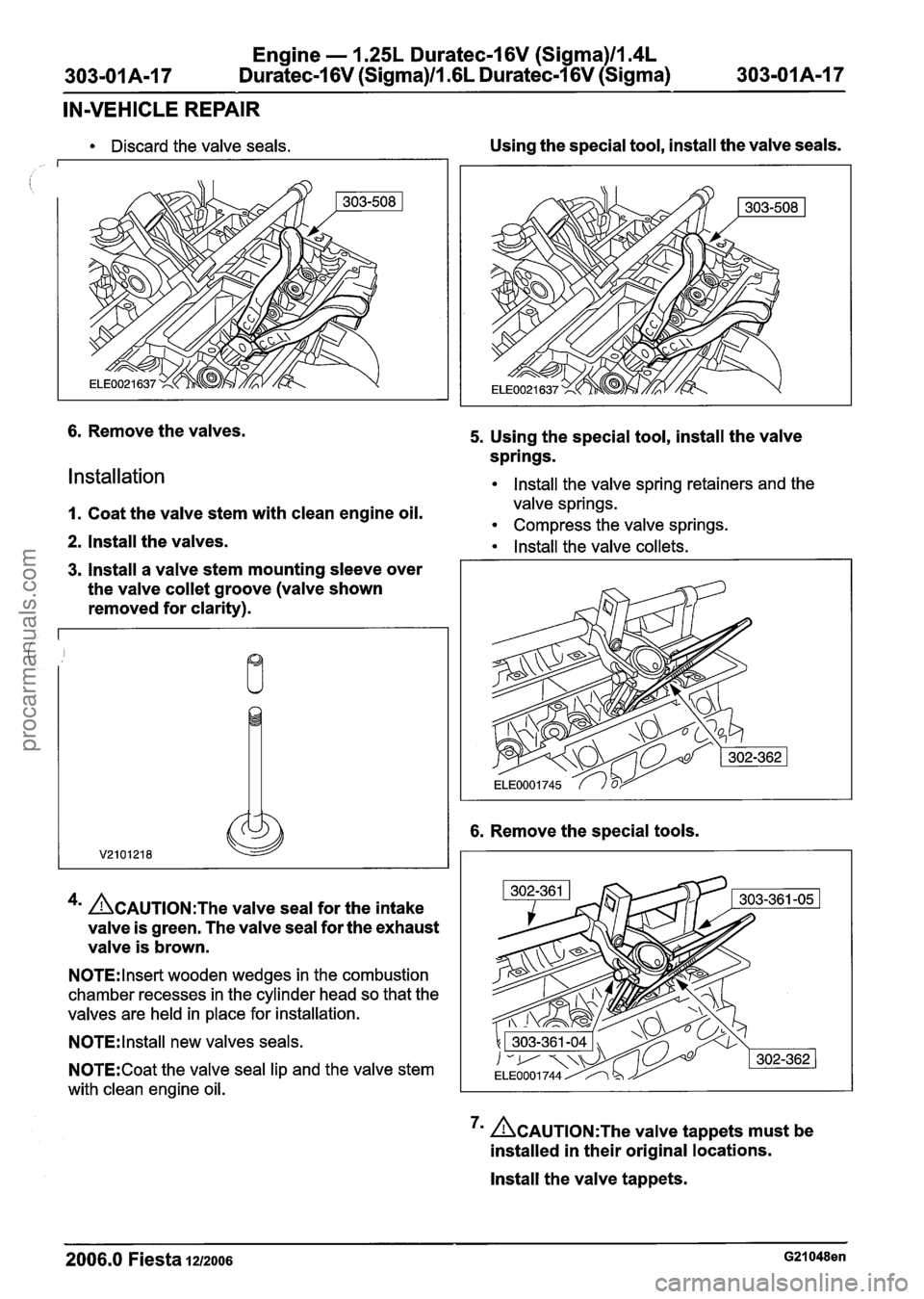
Discard the valve seals.
6. Remove the valves.
Installation
Using the special tool, install the valve seals.
5. Using the special tool, install the valve
springs.
lnstall the valve spring retainers and the
1. Coat the valve stem with clean engine oil. valve springs.
Compress the valve springs.
2. Install the valves. Install the valve collets.
3. lnstall a valve stem mounting sleeve over
the valve
collet groove (valve shown
removed for clarity).
4m ~AUTION:T~~ valve seal for the intake
valve is green. The valve seal for the exhaust
valve is brown.
N0TE:lnset-t wooden wedges in the combustion
chamber recesses in the cylinder head so that the
valves are held in place for installation.
N0TE:lnstall new valves seals.
N0TE:Coat the valve seal lip and the valve stem
with clean engine oil.
6. Remove the special tools.
7m &AUTION:T~~ valve tappets must be
installed in their original locations.
lnstall the valve tappets.
2006.0 Fiesta 1212006 G21048en
procarmanuals.com
Page 494 of 1226
Engine - 1.25L Duratec-1 6V (Sigma)ll.4L
303-01 A-I 8 Duratec-16V (Sigma)ll .6L Duratec-1 6V (Sigma) 303-01 A-I 8 - - -
IN-VEHICLE REPAIR
8. Install the cylinder head.
For additional information, refer to Cylinder
head in this section.
2006.0 Fiesta 1212006 G21048en
procarmanuals.com
Page 495 of 1226
Engine - 1.25L Duratec-I 6V (Sigma)ll.4L
303-01A-I 9 Duratec-1 6V (Sigma)/l .6L Duratec-1 6V (Sigma) 303-OIA-I 9
IN-VEHICLE REPAIR
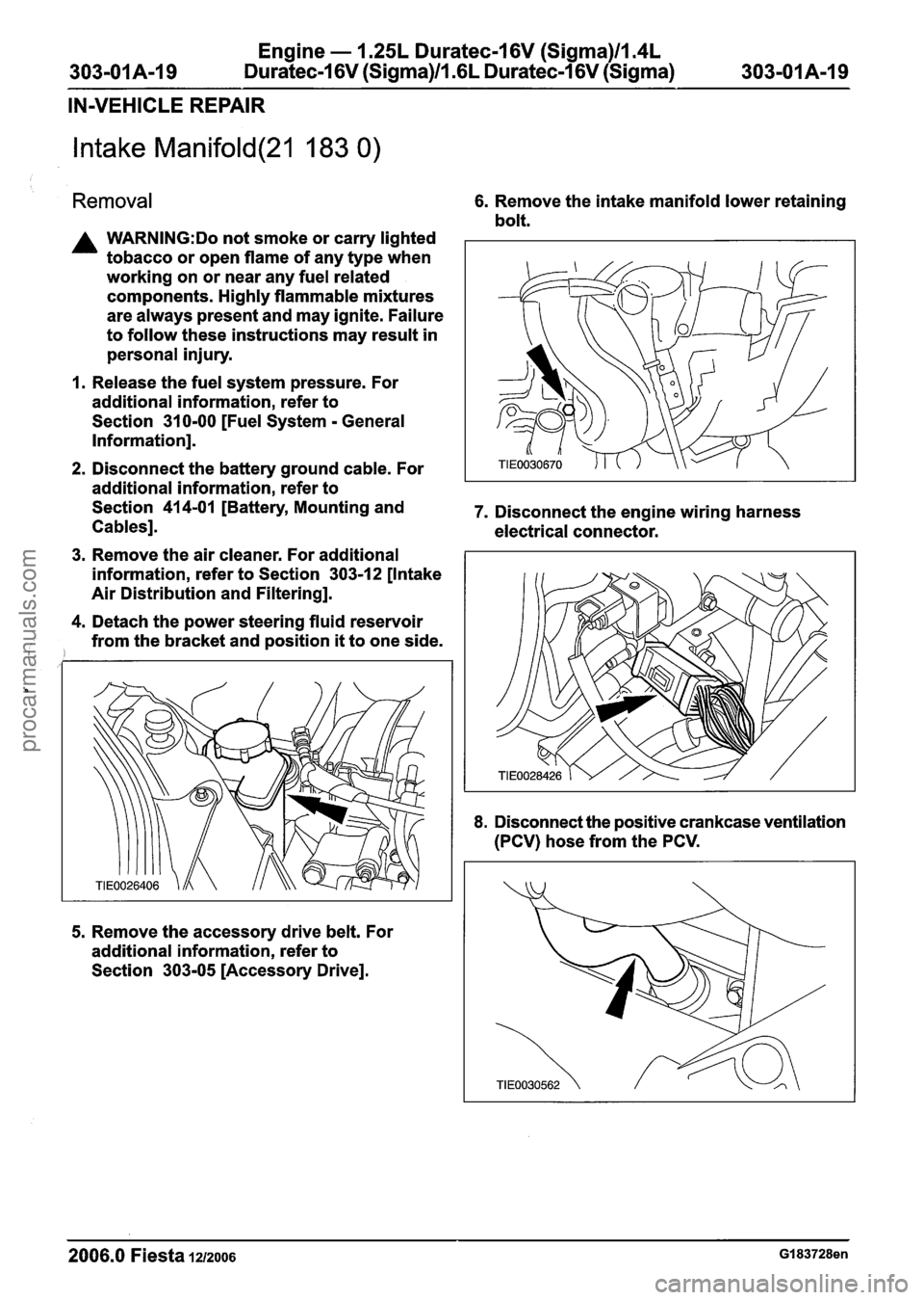
Intake Manifold(21 183 0)
Removal 6. Remove the intake manifold lower retaining
bolt.
A WARNING:Do not smoke or carry lighted
tobacco or open flame of any type when
working on or near any fuel related
components. Highly flammable mixtures
are always present and may ignite. Failure
to follow these instructions may result in
personal injury.
1. Release the fuel system pressure. For
additional information, refer to
Section
31 0-00 [Fuel System - General
Information].
2. Disconnect the battery ground cable. For
additional information, refer to
Section
414-01 [Battery, Mounting and 7. Disconnect the engine wiring harness
Cables]. electrical connector.
3. Remove the air cleaner. For additional
information, refer to Section
303-1 2 [Intake
Air Distribution and Filtering].
4. Detach the power steering fluid reservoir
from the bracket and position
it to one side.
5. Remove the accessory drive belt. For
additional information, refer to
Section
303-05 [Accessory Drive].
8. Disconnect the positive crankcase ventilation
(PCV) hose from the PCV.
2006.0 Fiesta 1212006 GI 83728en
procarmanuals.com
Page 496 of 1226
Engine - 1.25L Duratec-1 6V (Sigma)llm4L
303-01 A120 Duratec-1 6V (Sigma)ll .6L Duratec-1 6V (Sigma)
303-01 Am20
IN-VEHICLE REPAIR
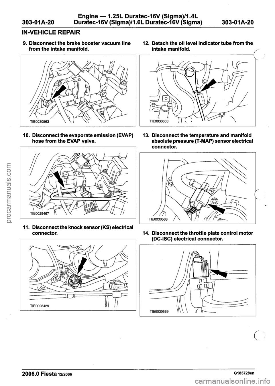
9. Disconnect the brake booster vacuum line
from the intake manifold. 12. Detach the oil level indicator tube from the
intake manifold.
/'-
10. Disconnect the evaporate emission (EVAP) 13. Disconnect the temperature and manifold
hose from the EVAP valve. absolute pressure (T-MAP) sensor electrical
connector.
11. Disconnect the knock sensor (KS) electrical
connector.
14. Disconnect the throttle plate control motor
(DC-ISC) electrical connector.
2006.0 Fiesta 1212006 GI 83728en
procarmanuals.com
Page 497 of 1226
Engine - 1.25L Duratec-I 6V (Sigma)ll14L
Duratec-1 6V (Sigma)ll16L Duratec-1 6V (Sigma)
IN-VEHICLE REPAIR
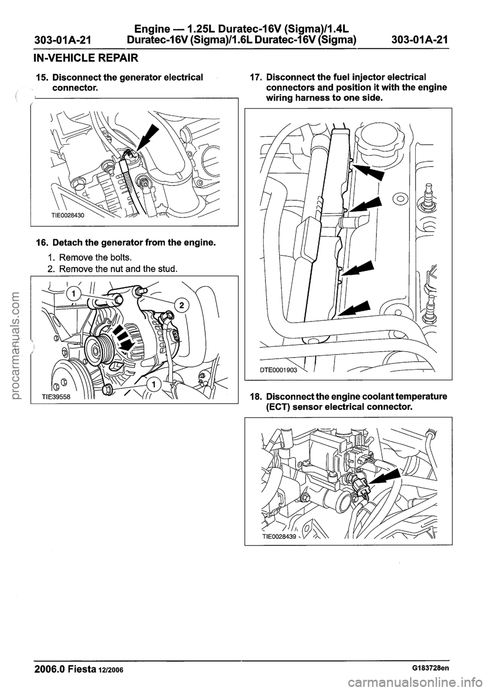
15. Disconnect the generator electrical 17. Disconnect the fuel injector electrical
connector. connectors and
position it with the engine
i wiring harness to one side.
16. Detach the generator from the engine.
1. Remove the bolts.
2. Remove the nut and the stud.
18. Disconnect the engine coolant temperature
(ECT) sensor electrical connector.
2006.0 Fiesta 1~12006 GI 83728en
procarmanuals.com
Page 498 of 1226
Engine - 1.25L Duratec-1 6V (Sigma)llI4L
Duratec-1 6V (Sigma)/l .6L Duratec-1 6V (Sigma)
IN-VEHICLE REPAIR
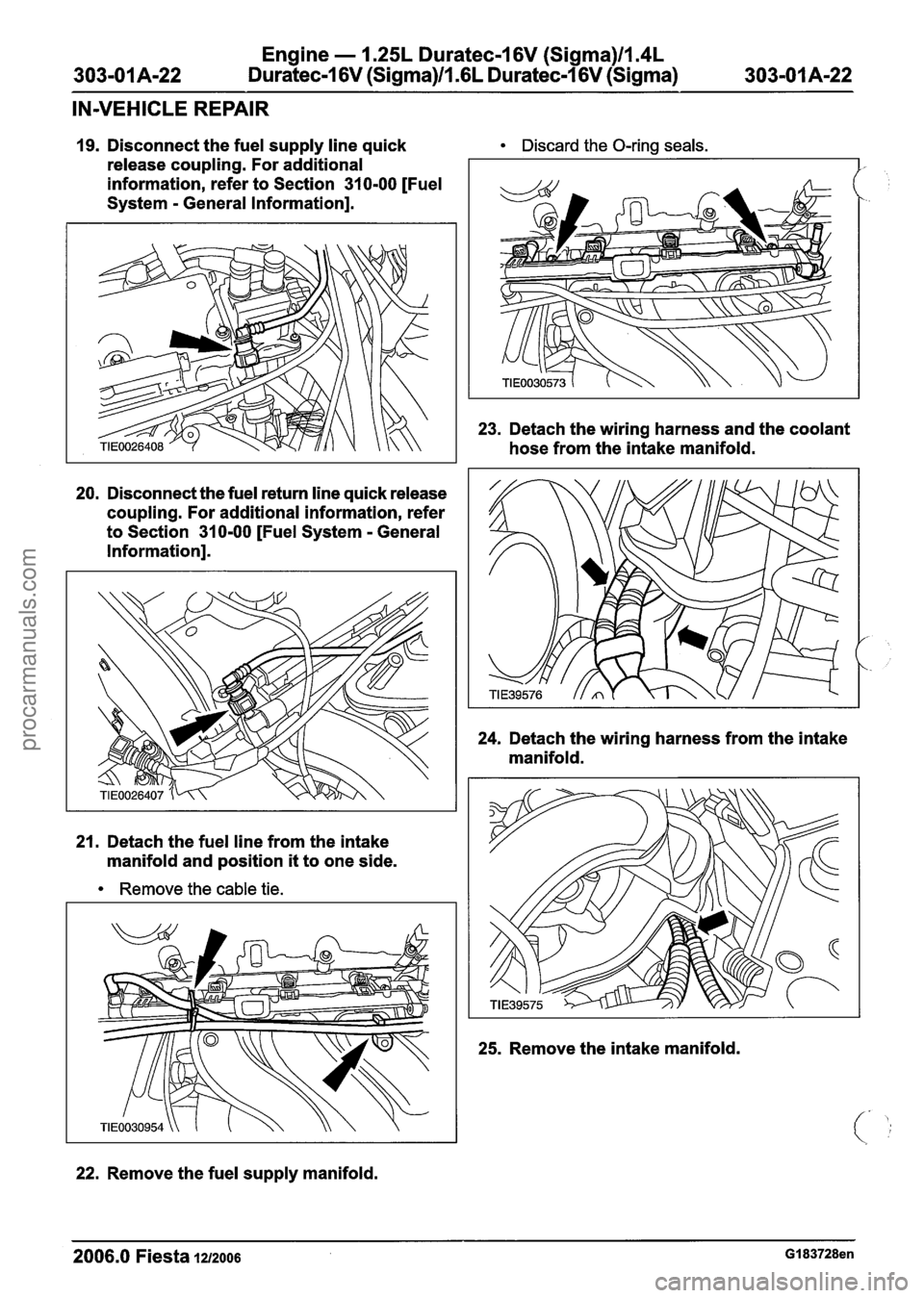
19. Disconnect the fuel supply line quick Discard the O-ring seals.
release coupling. For additional
information, refer to Section
31 0-00 [Fuel
System
- General Information].
20. Disconnect the fuel return line quick release
coupling. For additional information, refer
to Section
31 0-00 [Fuel System - General
Information].
21. Detach the fuel line from the intake
manifold and position
it to one side.
Remove the cable tie.
22.
Remove the fuel supply manifold.
23. Detach the wiring harness and the coolant
hose from the intake manifold.
24. Detach the wiring harness from the intake
manifold.
25. Remove the intake manifold.
2006.0 Fiesta 1212006 GI 83728en
procarmanuals.com
Page 499 of 1226
Engine - 1.25L Dura
303-01 A-23 Duratec-1
6V (Sigma)ll .(
:ec-I 6V (Sigma)llm4L
L
Duratec-1 6V (Sigma)
303-01 Am23
IN-VEHICLE REPAIR
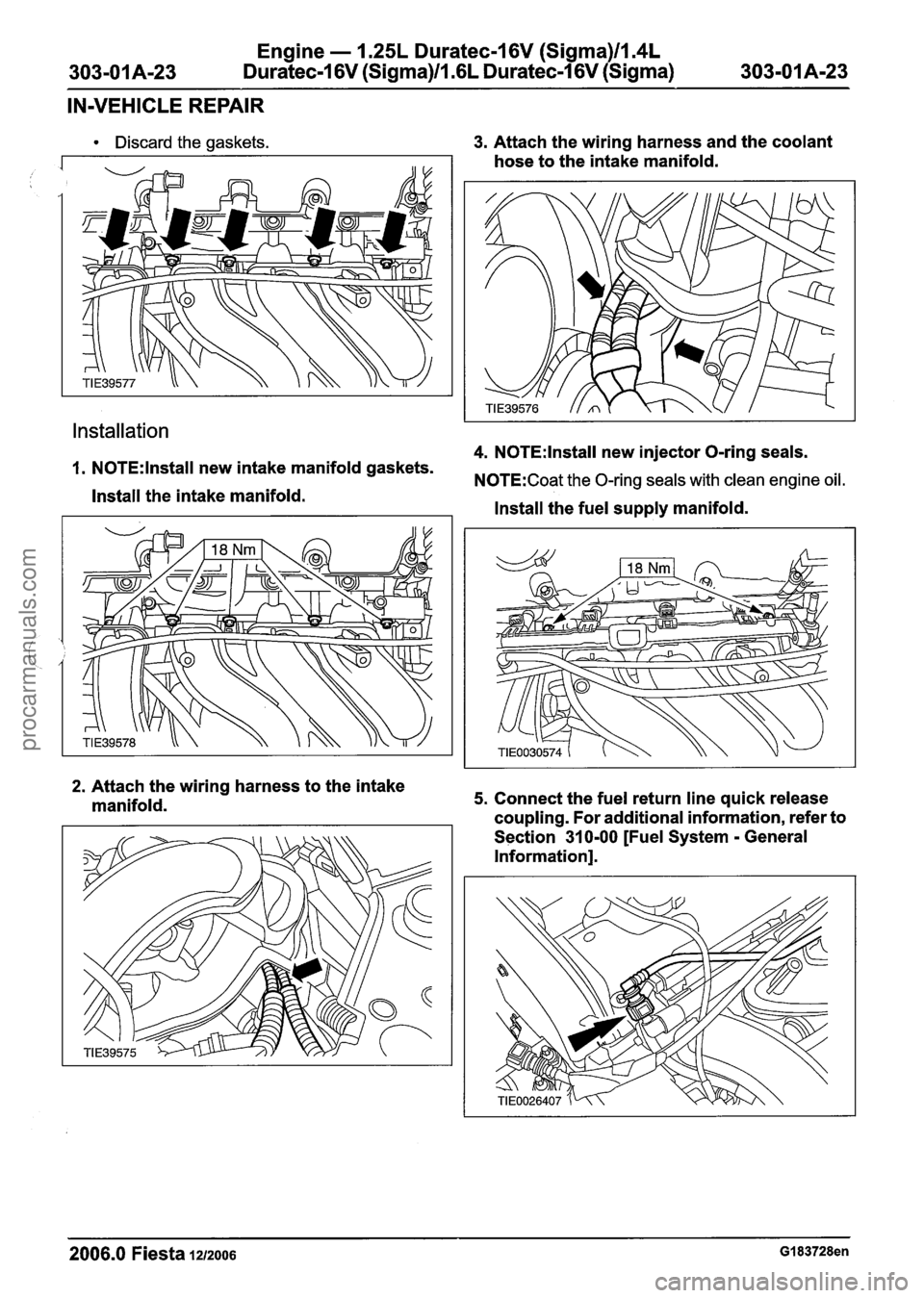
Discard the gaskets.
Installation
3. Attach the wiring harness and the coolant
hose to the intake manifold.
4. N0TE:lnstall new injector O-ring seals.
1. N0TE:lnstall new intake manifold gaskets. N0TE:Coat the 0-rina seals with clean enaine oil.
Install the intake manifold. V "
Install the fuel supply manifold.
2. Attach the wiring harness to the intake
manifold. 5. Connect the fuel return line quick release
coupling. For additional information, refer to
Section
31 0-00 [Fuel System - General
Information].
2006.0 Fiesta 1212006 GI 83728en
procarmanuals.com
Page 500 of 1226
Engine - 1.25L Duratec-1 6V (Sigma)llI4L
Duratec-1 6V (Sigma)/l .6L Duratec-1 6V (Sigma)
IN-VEHICLE REPAIR
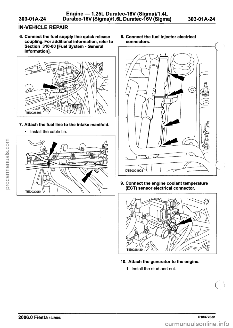
6. Connect the fuel supply line quick release
coupling. For additional information, refer to
Section 310-00 [Fuel System
- General
Information].
7. Attach the fuel line to the intake manifold.
Install the cable tie. 8.
Connect the fuel injector electrical
connectors.
9. Connect the engine coolant temperature
(ECT) sensor electrical connector.
10. Attach the generator to the engine.
1. Install the stud and nut.
2006.0 Fiesta 1212006 GI 83728en
procarmanuals.com