headlamp FORD FUSION HYBRID 2014 User Guide
[x] Cancel search | Manufacturer: FORD, Model Year: 2014, Model line: FUSION HYBRID, Model: FORD FUSION HYBRID 2014Pages: 473, PDF Size: 5.93 MB
Page 140 of 473
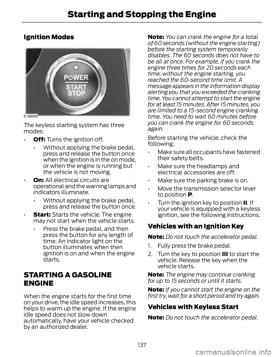
Ignition Modes E169299
The keyless starting system has three
modes:
• Off: Turns the ignition off.
• Without applying the brake pedal,
press and release the button once
when the ignition is in the on mode,
or when the engine is running but
the vehicle is not moving.
• On: All electrical circuits are
operational and the warning lamps and
indicators illuminate.
• Without applying the brake pedal,
press and release the button once.
• Start: Starts the vehicle. The engine
may not start when the vehicle starts.
• Press the brake pedal, and then
press the button for any length of
time. An indicator light on the
button illuminates when then
ignition is on and when the engine
starts.
STARTING A GASOLINE
ENGINE When the engine starts for the first time
on your drive, the idle speed increases, this
helps to warm up the engine. If the engine
idle speed does not slow down
automatically, have your vehicle checked
by an authorized dealer. Note: You can crank the engine for a total
of 60 seconds (without the engine starting)
before the starting system temporarily
disables. The 60 seconds does not have to
be all at once. For example, if you crank the
engine three times for 20 seconds each
time, without the engine starting, you
reached the 60-second time limit. A
message appears in the information display
alerting you that you exceeded the cranking
time. You cannot attempt to start the engine
for at least 15 minutes. After 15 minutes, you
are limited to a 15-second engine cranking
time. You need to wait 60 minutes before
you can crank the engine for 60 seconds
again.
Before starting the vehicle, check the
following:
• Make sure all occupants have fastened
their safety belts.
• Make sure the headlamps and
electrical accessories are off.
• Make sure the parking brake is on.
• Move the transmission selector lever
to position P .
• Turn the ignition key to position II . If
your vehicle is equipped with a keyless
ignition, see the following instructions.
Vehicles with an Ignition Key Note: Do not touch the accelerator pedal.
1. Fully press the brake pedal.
2. Turn the key to position III to start the
vehicle. Release the key when the
vehicle starts.
Note: The engine may continue cranking
for up to 15 seconds or until it starts.
Note: If you cannot start the engine on the
first try, wait for a short period and try again.
Vehicles with Keyless Start
Note: Do not touch the accelerator pedal.
137Starting and Stopping the Engine
Page 198 of 473
•Low
• Medium
• High
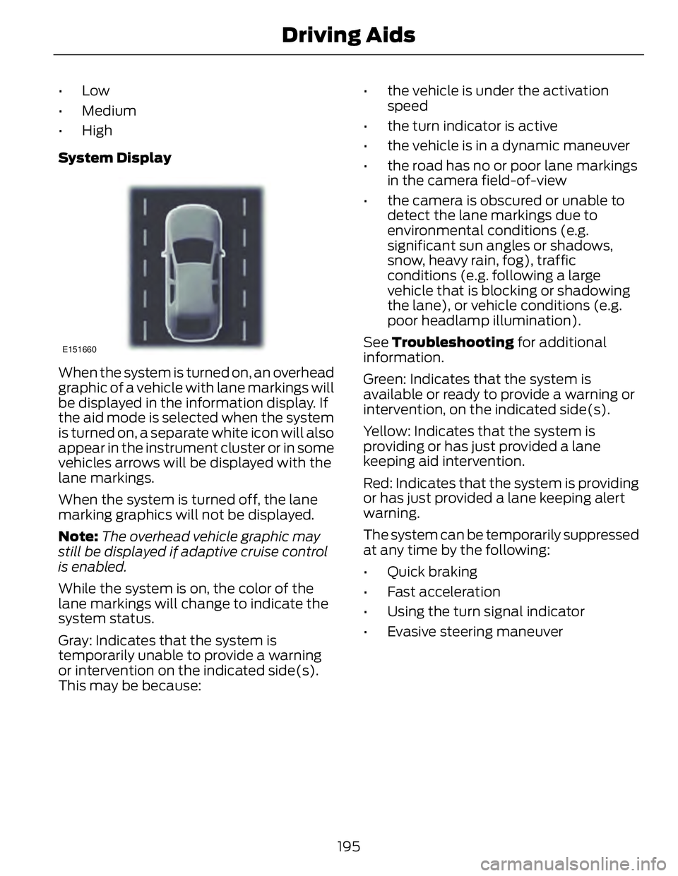
System Display E151660
When the system is turned on, an overhead
graphic of a vehicle with lane markings will
be displayed in the information display. If
the aid mode is selected when the system
is turned on, a separate white icon will also
appear in the instrument cluster or in some
vehicles arrows will be displayed with the
lane markings.
When the system is turned off, the lane
marking graphics will not be displayed.
Note: The overhead vehicle graphic may
still be displayed if adaptive cruise control
is enabled.
While the system is on, the color of the
lane markings will change to indicate the
system status.
Gray: Indicates that the system is
temporarily unable to provide a warning
or intervention on the indicated side(s).
This may be because: • the vehicle is under the activation
speed
• the turn indicator is active
• the vehicle is in a dynamic maneuver
• the road has no or poor lane markings
in the camera field-of-view
• the camera is obscured or unable to
detect the lane markings due to
environmental conditions (e.g.
significant sun angles or shadows,
snow, heavy rain, fog), traffic
conditions (e.g. following a large
vehicle that is blocking or shadowing
the lane), or vehicle conditions (e.g.
poor headlamp illumination).
See Troubleshooting for additional
information.
Green: Indicates that the system is
available or ready to provide a warning or
intervention, on the indicated side(s).
Yellow: Indicates that the system is
providing or has just provided a lane
keeping aid intervention.
Red: Indicates that the system is providing
or has just provided a lane keeping alert
warning.
The system can be temporarily suppressed
at any time by the following:
• Quick braking
• Fast acceleration
• Using the turn signal indicator
• Evasive steering maneuver
195Driving Aids
Page 207 of 473
ActionCause
Clean the grille surface in front of the radar
or remove the object causing the obstruc-
tionThe surface of the radar in the grille is dirty
or obstructed in some way
Wait a short time. It may take several
minutes for the radar to detect that it is no
longer obstructedThe surface of the radar in the grille is clean
but the message remains in the display
The collision warning system is temporarily
disabled. Collision warning should automat-
ically reactivate a short time after the
weather conditions improveHeavy rain, spray, snow, or fog is interfering
with the radar signals
The collision warning system is temporarily
disabled. Collision warning should automat-
ically reactivate a short time after the
weather conditions improveSwirling water, or snow or ice on the surface
of the road may interfere with the radar
signals
System Limitations
WARNING
The collision warning system’s brake
support can only help reduce the
speed at which a collision occurs if
the driver applies the vehicle’s brakes. The
brake pedal must be pressed just like any
typical braking situation.
Due to the nature of radar technology,
there may be certain instances where
vehicles do not provide a collision warning.
These include:
• Stationary vehicles or vehicles moving
below 6 mph (10 km/h).
• Pedestrians or objects in the roadway.
• Oncoming vehicles in the same lane.
• Severe weather conditions (see
blocked sensor section).
• Debris build-up on the grille near the
headlamps (see blocked sensor
section).
• Small distance to vehicle ahead. • Steering wheel and pedal movements
are large (very active driving style).
•
If the front end of the vehicle is hit or
damaged, the radar sensing zone may be
altered causing missed or false collision
warnings. See your authorized dealer to
have your collision warning radar checked
for proper coverage and operation.
204Driving Aids
Page 256 of 473

ADJUSTING THE HEADLAMPS Vertical Aim Adjustment The headlamps on your vehicle are
properly aimed at the assembly plant. If
your vehicle has been in an accident, the
alignment of your headlamps should be
checked by your authorized dealer.
Headlamp Aiming Target E142592
8 feet (2.4 meters)A
Center height of lamp to groundB
25 feet (7.6 meters)C
Horizontal reference lineD
Vertical Aim Adjustment Procedure
1. Park the vehicle directly in front of a
wall or screen on a level surface,
approximately 25 feet (7.6 meters)
away.
2. Measure the height of the headlamp
bulb center from the ground and mark
an 8 foot (2.4 meter) horizontal
reference line on the vertical wall or
screen at this height.
Note: To see a clearer light pattern for
adjusting, you may want to block the light
from one headlamp while adjusting the
other. 3. Turn on the low beam headlamps to
illuminate the wall or screen and open
the hood. E142465
4. On the wall or screen you will observe
a flat zone of high intensity light
located at the top of the right hand
portion of the beam pattern. If the top
edge of the high intensity light zone is
not at the horizontal reference line, the
headlamp will need to be adjusted.
E145594
5. Locate the vertical adjuster on each
headlamp. Using a Phillips #2
screwdriver, turn the adjuster either
clockwise or counterclockwise in order
to adjust the vertical aim of the
headlamp. The horizontal edge of the
brighter light should touch the
horizontal reference line.
6. Close the hood and turn off the lamps.
253Maintenance
Page 257 of 473
Horizontal Aim Adjustment Horizontal aim is not required for this
vehicle and is not adjustable.
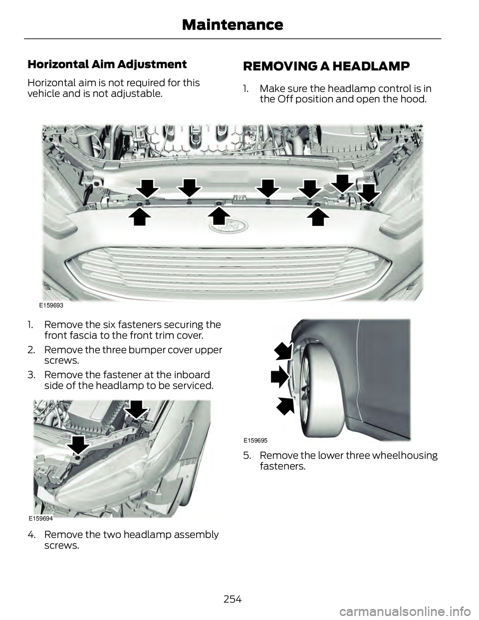
REMOVING A HEADLAMP 1. Make sure the headlamp control is in
the Off position and open the hood.
E159693
1. Remove the six fasteners securing the
front fascia to the front trim cover.
2. Remove the three bumper cover upper
screws.
3. Remove the fastener at the inboard
side of the headlamp to be serviced.
E159694
4. Remove the two headlamp assembly
screws. E159695
5. Remove the lower three wheelhousing
fasteners.
254Maintenance
Page 258 of 473
E159696
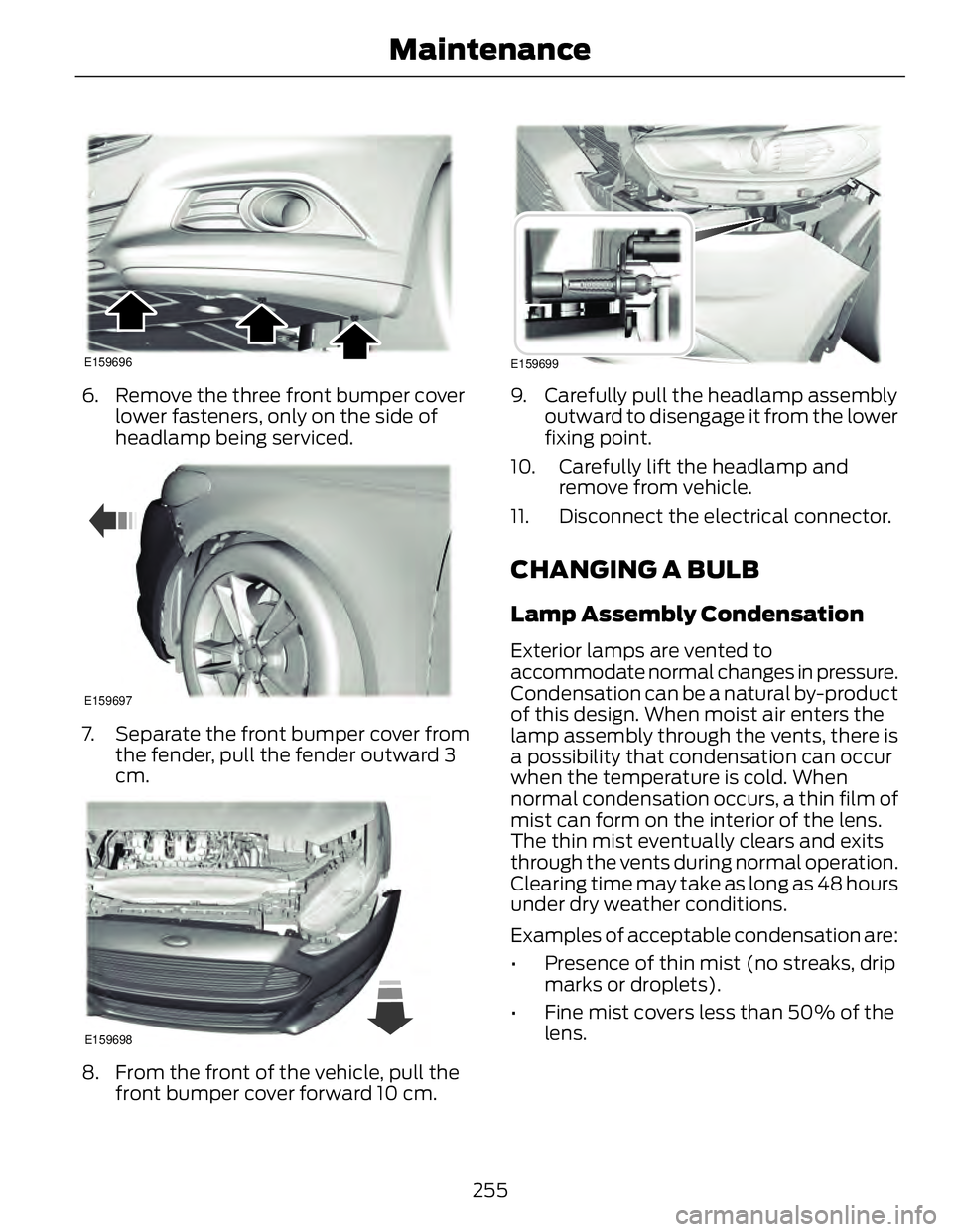
6. Remove the three front bumper cover
lower fasteners, only on the side of
headlamp being serviced. E159697
7. Separate the front bumper cover from
the fender, pull the fender outward 3
cm.
E159698
8. From the front of the vehicle, pull the
front bumper cover forward 10 cm. E159699
9. Carefully pull the headlamp assembly
outward to disengage it from the lower
fixing point.
10. Carefully lift the headlamp and
remove from vehicle.
11. Disconnect the electrical connector.
CHANGING A BULB Lamp Assembly Condensation Exterior lamps are vented to
accommodate normal changes in pressure.
Condensation can be a natural by-product
of this design. When moist air enters the
lamp assembly through the vents, there is
a possibility that condensation can occur
when the temperature is cold. When
normal condensation occurs, a thin film of
mist can form on the interior of the lens.
The thin mist eventually clears and exits
through the vents during normal operation.
Clearing time may take as long as 48 hours
under dry weather conditions.
Examples of acceptable condensation are:
• Presence of thin mist (no streaks, drip
marks or droplets).
• Fine mist covers less than 50% of the
lens.
255Maintenance
Page 259 of 473
Examples of unacceptable moisture
(usually caused by a lamp water leak) are:
• Water puddle inside the lamp.
• Large water droplets, drip marks or
streaks present on the interior of the
lens.
Take your vehicle to an authorized dealer
for service if any of the above conditions
of unacceptable moisture are present.
Replacing the Headlamp Bulbs WARNING
Handle a halogen headlamp bulb
carefully and keep out of children’s
reach. Grasp the bulb by only its
plastic base and do not touch the glass.
The oil from your hand could cause the
bulb to break the next time the headlamps
are operated.
Note: If the bulb is accidentally touched, it
should be cleaned with rubbing alcohol
before being used.
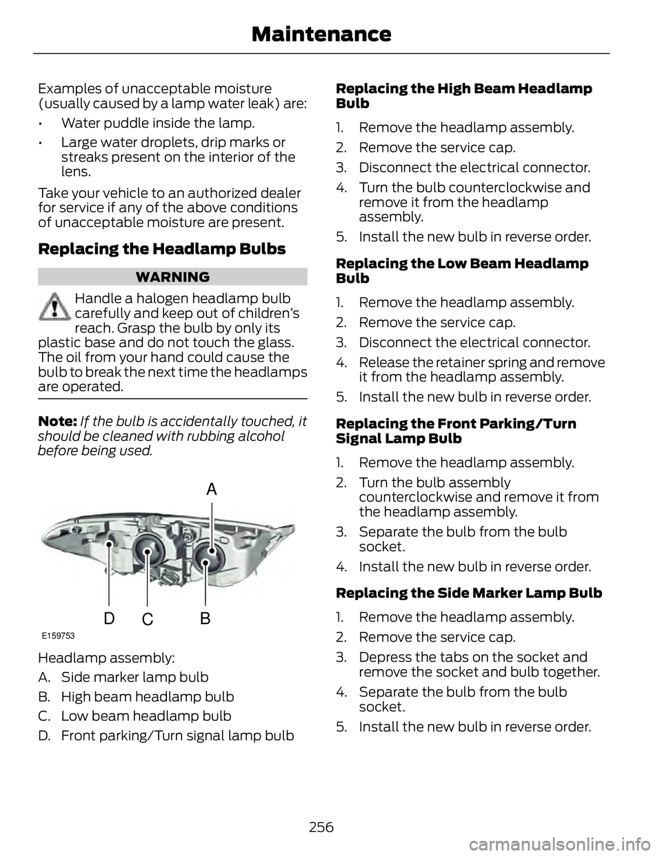
A
B
CDE159753
Headlamp assembly:
A. Side marker lamp bulb
B. High beam headlamp bulb
C. Low beam headlamp bulb
D. Front parking/Turn signal lamp bulb Replacing the High Beam Headlamp
Bulb
1. Remove the headlamp assembly.
2. Remove the service cap.
3. Disconnect the electrical connector.
4. Turn the bulb counterclockwise and
remove it from the headlamp
assembly.
5. Install the new bulb in reverse order.
Replacing the Low Beam Headlamp
Bulb
1. Remove the headlamp assembly.
2. Remove the service cap.
3. Disconnect the electrical connector.
4. Release the retainer spring and remove
it from the headlamp assembly.
5. Install the new bulb in reverse order.
Replacing the Front Parking/Turn
Signal Lamp Bulb
1. Remove the headlamp assembly.
2. Turn the bulb assembly
counterclockwise and remove it from
the headlamp assembly.
3. Separate the bulb from the bulb
socket.
4. Install the new bulb in reverse order.
Replacing the Side Marker Lamp Bulb
1. Remove the headlamp assembly.
2. Remove the service cap.
3. Depress the tabs on the socket and
remove the socket and bulb together.
4. Separate the bulb from the bulb
socket.
5. Install the new bulb in reverse order.
256Maintenance
Page 261 of 473
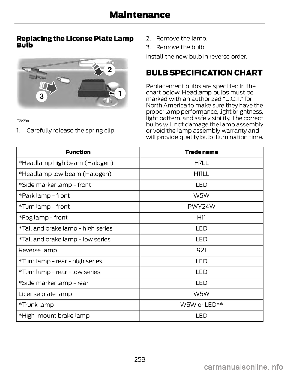
Replacing the License Plate Lamp
Bulb
3 2
1E72789
1. Carefully release the spring clip. 2. Remove the lamp.
3. Remove the bulb.
Install the new bulb in reverse order.
BULB SPECIFICATION CHART Replacement bulbs are specified in the
chart below. Headlamp bulbs must be
marked with an authorized “D.O.T.” for
North America to make sure they have the
proper lamp performance, light brightness,
light pattern, and safe visibility. The correct
bulbs will not damage the lamp assembly
or void the lamp assembly warranty and
will provide quality bulb illumination time. Trade nameFunction
H7LL*Headlamp high beam (Halogen)
H11LL*Headlamp low beam (Halogen)
LED*Side marker lamp - front
W5W*Park lamp - front
PWY24W*Turn lamp - front
H11*Fog lamp - front
LED*Tail and brake lamp - high series
LED*Tail and brake lamp - low series
921Reverse lamp
LED*Turn lamp - rear - high series
LED*Turn lamp - rear - low series
LED*Side marker lamp - rear
W5WLicense plate lamp
W5W or LED***Trunk lamp
LED*High-mount brake lamp
258Maintenance
Page 464 of 473
A A/C See: Climate Control..........................................113
About This Manual...........................................7 Protecting the Environment................................7
ABS See: Brakes...........................................................169
ABS driving hints See: Hints on Driving With Anti-Lock
Brakes.................................................................170
Accessories.....................................................314 Exterior style.........................................................314
Interior style..........................................................314
Lifestyle..................................................................314
Peace of mind......................................................314
Accessories See: Replacement Parts
Recommendation .............................................11
ACC See: Using Adaptive Cruise Control............186
Active Park Assist.........................................178 Automatic Steering into Parking
Space..................................................................179
Deactivating the Park Assist Feature.........180
Troubleshooting the System.........................180
Using Active Park Assist...................................178
Adjusting the Headlamps.........................253 Horizontal Aim Adjustment...........................254
Vertical Aim Adjustment.................................253
Adjusting the Steering Wheel...................64
Airbag Disposal...............................................43
Air Conditioning See: Climate Control..........................................113
Alarm See: Anti-Theft Alarm........................................63
Ambient Lighting............................................73
Anti-Theft Alarm............................................63 Arming the Alarm.................................................63
Disarming the Alarm...........................................63
Appendices ....................................................429
Audible Warnings and Indicators.............85 Headlamps On Warning Chime......................85
Key in Ignition Warning Chime........................85
Keyless Warning Alert........................................85
Parking Brake On Warning Chime.................85 Audio Control..................................................64 MEDIA .......................................................................64
Seek, Next or Previous.......................................64
Audio System................................................299 General Information.........................................299
Audio unit - Vehicles With:
AM/FM/CD/SYNC/Satellite
Radio.............................................................300
Audio unit - Vehicles With: Premium
AM/FM/CD..................................................302
Audio unit - Vehicles With: Sony
AM/FM/CD .................................................304Menu Structure..................................................305
Autolamps........................................................69
Automatic Climate Control........................113
Automatic High Beam Control...................71 Activating the System..........................................71
Manually Overriding the System.....................72
Automatic Transmission...........................166 Automatic Transmission.................................166
Brake-Shift Interlock..........................................167
If Your Vehicle Gets Stuck In Mud or
Snow..................................................................168
Automatic Transmission Fluid
Check............................................................249
Autowiper s........................................................67
Auxiliary Input Jack.......................................312
Auxiliary Power Points................................133 110 Volt AC Power Point....................................133
12 Volt DC Power Point.....................................133
Locations................................................................133
B Blind Spot Monitor.......................................197 Blind Spot Information System (BLIS®)
with Cross Traffic Alert.................................197
Bonnet Lock See: Opening and Closing the Hood...........241
Booster Seats...................................................16 Types of Booster Seats.......................................16
Brake Fluid Check........................................249
Brakes...............................................................169 General Information..........................................169
Breaking-In ...................................................... 215
Bulb Specification Chart..........................258
461Index
Page 465 of 473
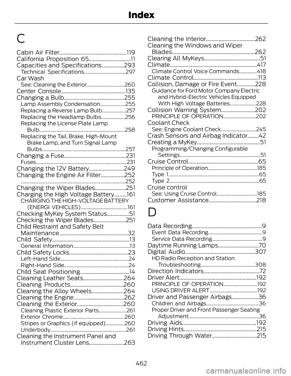
C Cabin Air Filter................................................119
California Proposition 65..............................11
Capacities and Specifications................293 Technical Specifications.................................297
Car Wash See: Cleaning the Exterior..............................260
Center Console..............................................135
Changing a Bulb...........................................255 Lamp Assembly Condensation....................255
Replacing a Reverse Lamp Bulb...................257
Replacing the Headlamp Bulbs...................256
Replacing the License Plate Lamp
Bulb .................................................................... 258
Replacing the Tail, Brake, High-Mount
Brake Lamp, and Turn Signal Lamp
Bulbs ..................................................................257
Changing a Fuse............................................231 Fuses ........................................................................231
Changing the 12V Battery.........................249
Changing the Engine Air Filter.................252 ...................................................................................252
Changing the Wiper Blades......................251
Charging the High Voltage Battery.........161 CHARGING THE HIGH-VOLTAGE BATTERY
(ENERGI VEHICLES).....................................161
Checking MyKey System Status................51
Checking the Wiper Blades.......................251
Child Restraint and Safety Belt
Maintenance .................................................32
Child Safety.......................................................13 General Information.............................................13
Child Safety Locks..........................................23 Left-Hand Side......................................................24
Right-Hand Side...................................................24
Child Seat Positioning...................................14
Cleaning Leather Seats.............................264
Cleaning Products......................................260
Cleaning the Alloy Wheels.......................264
Cleaning the Engine....................................262
Cleaning the Exterior.................................260 Cleaning Plastic Exterior Parts......................261
Exterior Chrome.................................................260
Stripes or Graphics (if equipped)...............260
Underbody ............................................................261
Cleaning the Instrument Panel and
Instrument Cluster Lens.........................263 Cleaning the Interior...................................262
Cleaning the Windows and Wiper
Blades...........................................................262
Clearing All MyKeys........................................51
Climate..............................................................417 Climate Control Voice Commands..............418
Climate Control..............................................113
Collision, Damage or Fire Event.............228 Guidance for Ford Motor Company Electric
and Hybrid-Electric Vehicles Equipped
With High Voltage Batteries.....................228
Collision Warning System........................202 PRINCIPLE OF OPERATION..........................202
Coolant Check See: Engine Coolant Check............................245
Crash Sensors and Airbag Indicator........42
Creating a MyKey.............................................51 Programming/Changing Configurable
Settings ................................................................51
Cruise Control..................................................65 Principle of Operation.......................................185
Type 1........................................................................65
Type 2.......................................................................65
Cruise control See: Using Cruise Control................................185
Customer Assistance..................................218
D Data Recording..................................................9 Event Data Recording...........................................9
Service Data Recording........................................9
Daytime Running Lamps.............................70
Digital Audio..................................................307 HD Radio Reception and Station
Troubleshooting ...........................................308
Direction Indicators........................................72
Driver Alert.......................................................192 PRINCIPLE OF OPERATION...........................192
USING DRIVER ALERT......................................192
Driver and Passenger Airbags...................36 Children and Airbags..........................................36
Proper Driver and Front Passenger Seating
Adjust ment........................................................ 36
Driving Aids.....................................................192
Driving Hints....................................................215
Driving Through Water................................215
462Index