FORD KUGA 2011 1.G Workshop Manual
KUGA 2011 1.G
FORD
FORD
https://www.carmanualsonline.info/img/11/5478/w960_5478-0.png
FORD KUGA 2011 1.G Workshop Manual
Trending: rf receiver, pressure, oil additives, instrument panel, tdci, wipers, parking brake
Page 1551 of 2057
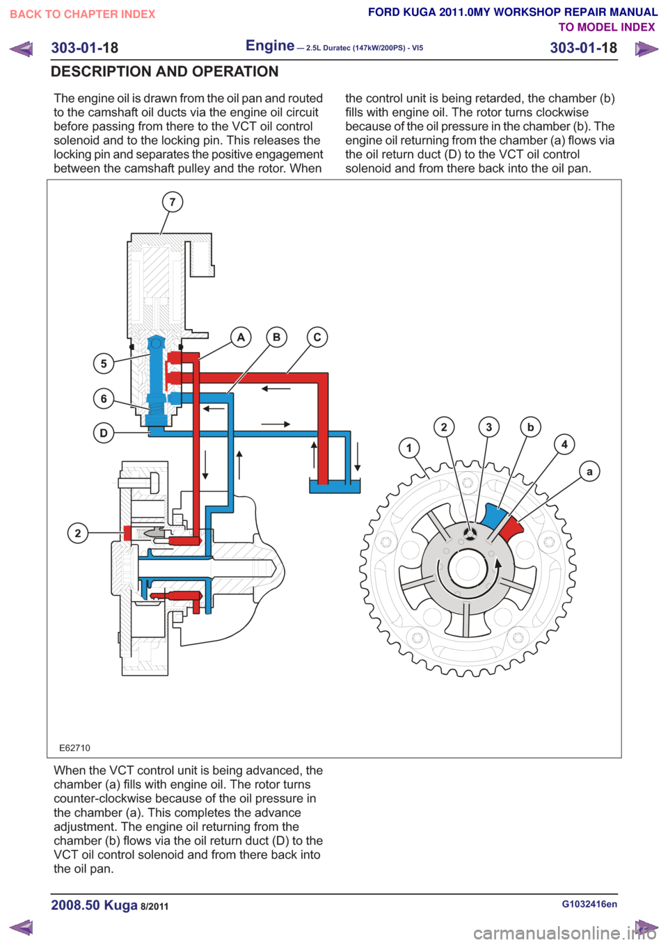
The engine oil is drawn from the oil pan and routed
to the camshaft oil ducts via the engine oil circuit
before passing from there to the VCT oil control
solenoid and to the locking pin. This releases the
locking pin and separates the positive engagement
between the camshaft pulley and the rotor. Whenthe control unit is being retarded, the chamber (b)
fills with engine oil. The rotor turns clockwise
because of the oil pressure in the chamber (b). The
engine oil returning from the chamber (a) flows via
the oil return duct (D) to the VCT oil control
solenoid and from there back into the oil pan.
E62710
When the VCT control unit is being advanced, the
chamber (a) fills with engine oil. The rotor turns
counter-clockwise because of the oil pressure in
the chamber (a). This completes the advance
adjustment. The engine oil returning from the
chamber (b) flows via the oil return duct (D) to the
VCT oil control solenoid and from there back into
the oil pan.
G1032416en2008.50 Kuga8/2011
303-01-
18
Engine— 2.5L Duratec (147kW/200PS) - VI5303-01-
18
DESCRIPTION AND OPERATION
TO MODEL INDEX
BACK TO CHAPTER INDEX
FORD KUGA 2011.0MY WORKSHOP REPAIR MANUAL
Page 1552 of 2057
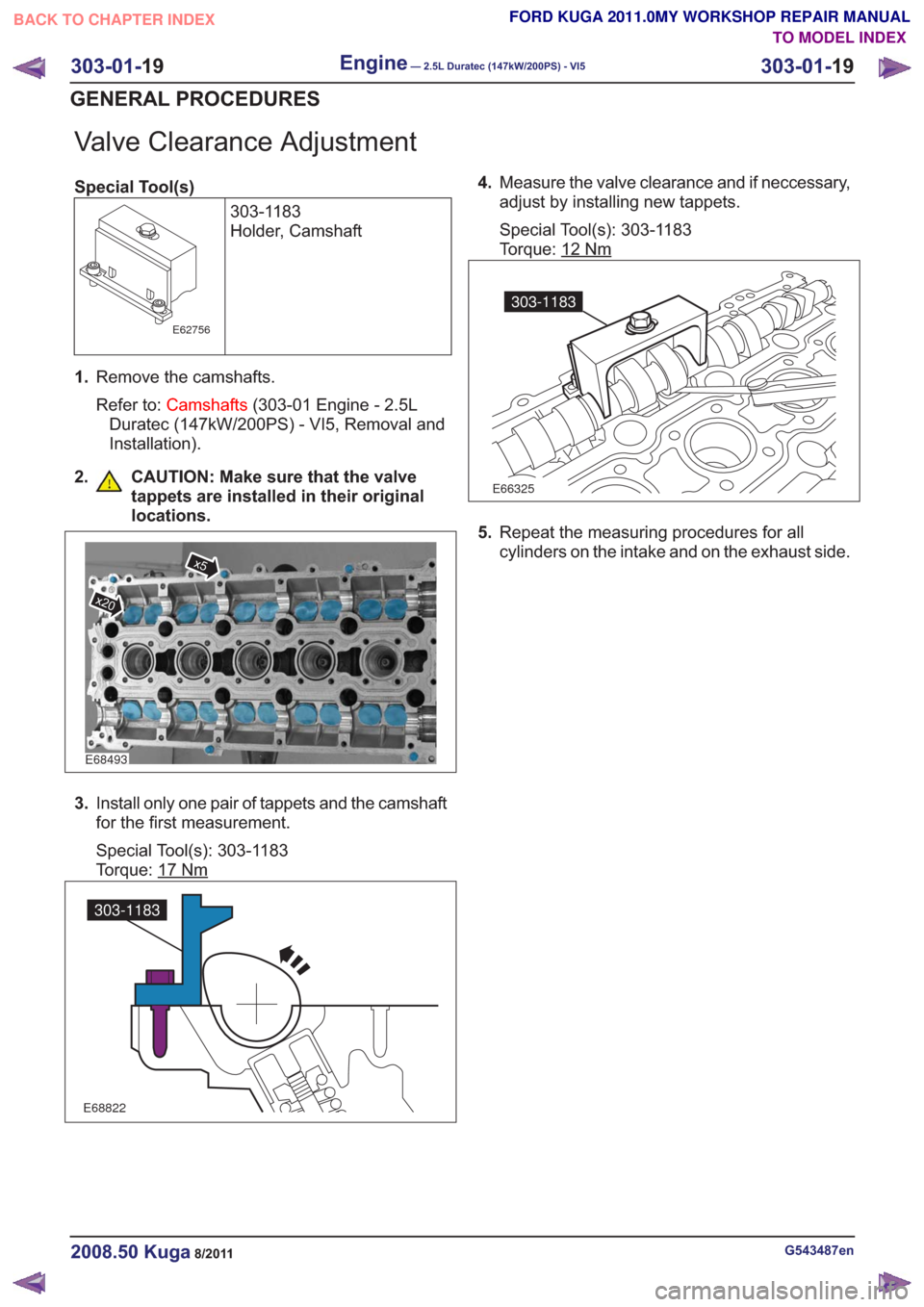
Valve Clearance Adjustment
Special Tool(s)303-1183
Holder, Camshaft
E62756
1.Remove the camshafts.
Refer to: Camshafts (303-01 Engine - 2.5L
Duratec (147kW/200PS) - VI5, Removal and
Installation).
2. CAUTION: Make sure that the valve tappets are installed in their original
locations.
E68493
x20
x5
3.Install only one pair of tappets and the camshaft
for the first measurement.
Special Tool(s): 303-1183
Torque: 17
Nm
E68822
303-1183
4.Measure the valve clearance and if neccessary,
adjust by installing new tappets.
Special Tool(s): 303-1183
Torque: 12
Nm
E66325
303-1183
5.Repeat the measuring procedures for all
cylinders on the intake and on the exhaust side.
G543487en2008.50 Kuga8/2011
303-01- 19
Engine— 2.5L Duratec (147kW/200PS) - VI5303-01-
19
GENERAL PROCEDURES
TO MODEL INDEX
BACK TO CHAPTER INDEX
FORD KUGA 2011.0MY WORKSHOP REPAIR MANUAL
Page 1553 of 2057
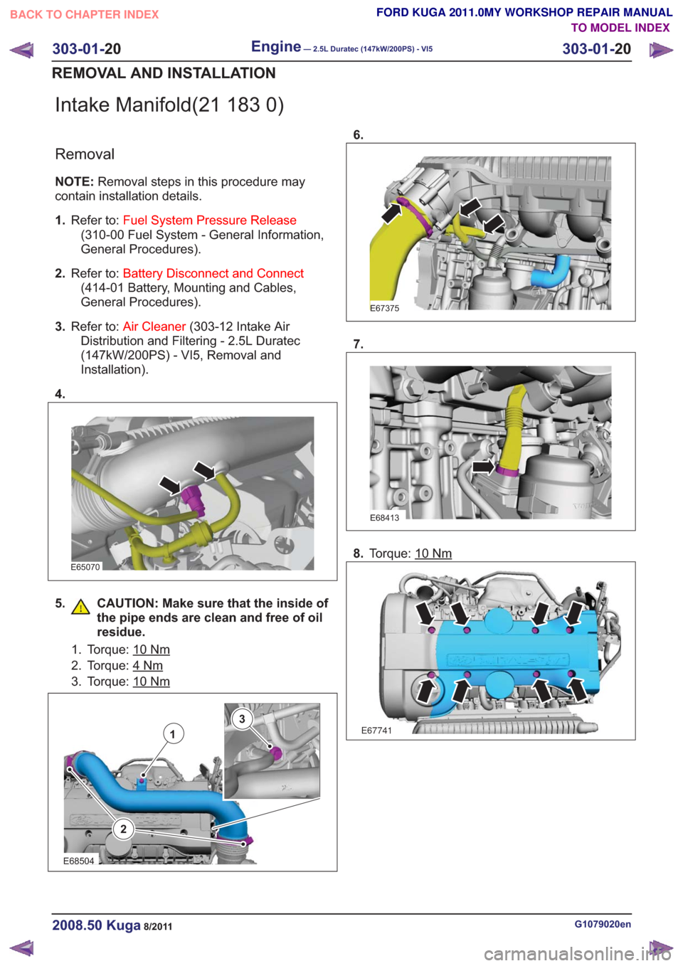
Intake Manifold(21 183 0)
Removal
NOTE:Removal steps in this procedure may
contain installation details.
1. Refer to: Fuel System Pressure Release
(310-00 Fuel System - General Information,
General Procedures).
2. Refer to: Battery Disconnect and Connect
(414-01 Battery, Mounting and Cables,
General Procedures).
3. Refer to: Air Cleaner (303-12 Intake Air
Distribution and Filtering - 2.5L Duratec
(147kW/200PS) - VI5, Removal and
Installation).
4.
E65070
5. CAUTION: Make sure that the inside of the pipe ends are clean and free of oil
residue.
1. Torque: 10Nm
2. Torque: 4Nm
3. Torque: 10Nm
2
1
3
E68504
6.
E67375
7.
E68413
8.Torque: 10Nm
E67741
G1079020en2008.50 Kuga8/2011
303-01- 20
Engine— 2.5L Duratec (147kW/200PS) - VI5303-01-
20
REMOVAL AND INSTALLATION
TO MODEL INDEX
BACK TO CHAPTER INDEX
FORD KUGA 2011.0MY WORKSHOP REPAIR MANUAL
Page 1554 of 2057
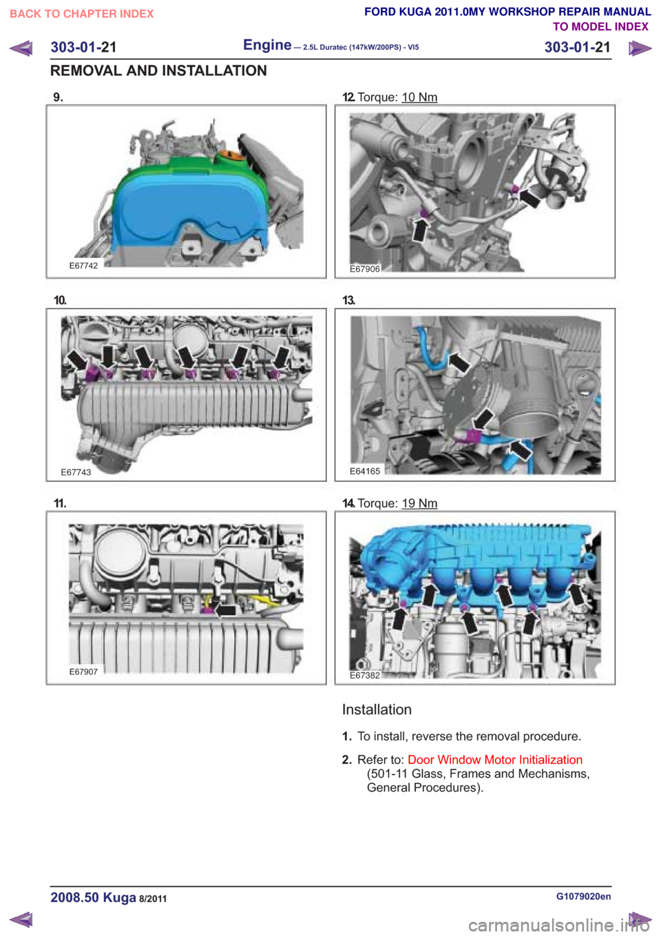
9.
E67742
10.
E67743
11 .
E67907
12.Torque: 10Nm
E67906
13.
E64165
14.Torque: 19Nm
Installation
1.To install, reverse the removal procedure.
2. Refer to: Door Window Motor Initialization
(501-11 Glass, Frames and Mechanisms,
General Procedures).
G1079020en2008.50 Kuga8/2011
303-01- 21
Engine— 2.5L Duratec (147kW/200PS) - VI5303-01-
21
REMOVAL AND INSTALLATION
TO MODEL INDEX
BACK TO CHAPTER INDEX
FORD KUGA 2011.0MY WORKSHOP REPAIR MANUAL
E67382
Page 1555 of 2057
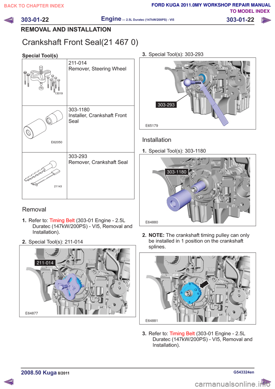
Crankshaft Front Seal(21 467 0)
Special Tool(s)211-014
Remover, Steering Wheel
13019
303-1180
Installer, Crankshaft Front
Seal
E62050
303-293
Remover, Crankshaft Seal
21143
Removal
1.Refer to: Timing Belt (303-01 Engine - 2.5L
Duratec (147kW/200PS) - VI5, Removal and
Installation).
2. Special Tool(s): 211-014
E64877
211-014
3.Special Tool(s): 303-293
E65179
303-293
Installation
1.Special Tool(s): 303-1180
E64880
303-1180
2. NOTE: The crankshaft timing pulley can only
be installed in 1 position on the crankshaft
splines.
E64881
3. Refer to: Timing Belt (303-01 Engine - 2.5L
Duratec (147kW/200PS) - VI5, Removal and
Installation).
G543324en2008.50 Kuga8/2011
303-01- 22
Engine— 2.5L Duratec (147kW/200PS) - VI5303-01-
22
REMOVAL AND INSTALLATION
TO MODEL INDEX
BACK TO CHAPTER INDEX
FORD KUGA 2011.0MY WORKSHOP REPAIR MANUAL
Page 1556 of 2057
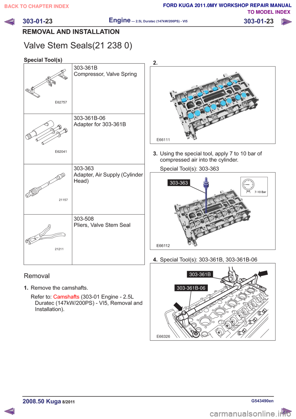
Valve Stem Seals(21 238 0)
Special Tool(s)303-361B
Compressor, Valve Spring
E62757
303-361B-06
Adapter for 303-361B
E62041
303-363
Adapter, Air Supply (Cylinder
Head)
21157
303-508
Pliers, Valve Stem Seal
21211
Removal
1.Remove the camshafts.
Refer to: Camshafts (303-01 Engine - 2.5L
Duratec (147kW/200PS) - VI5, Removal and
Installation). 2.
E66111
3.
Using the special tool, apply 7 to 10 bar of
compressed air into the cylinder.
Special Tool(s): 303-363
E66112
303-363
4.Special Tool(s): 303-361B, 303-361B-06
E66326
303-361B
303-361B-06
G543490en2008.50 Kuga8/2011
303-01- 23
Engine— 2.5L Duratec (147kW/200PS) - VI5303-01-
23
REMOVAL AND INSTALLATION
TO MODEL INDEX
BACK TO CHAPTER INDEX
FORD KUGA 2011.0MY WORKSHOP REPAIR MANUAL
Page 1557 of 2057
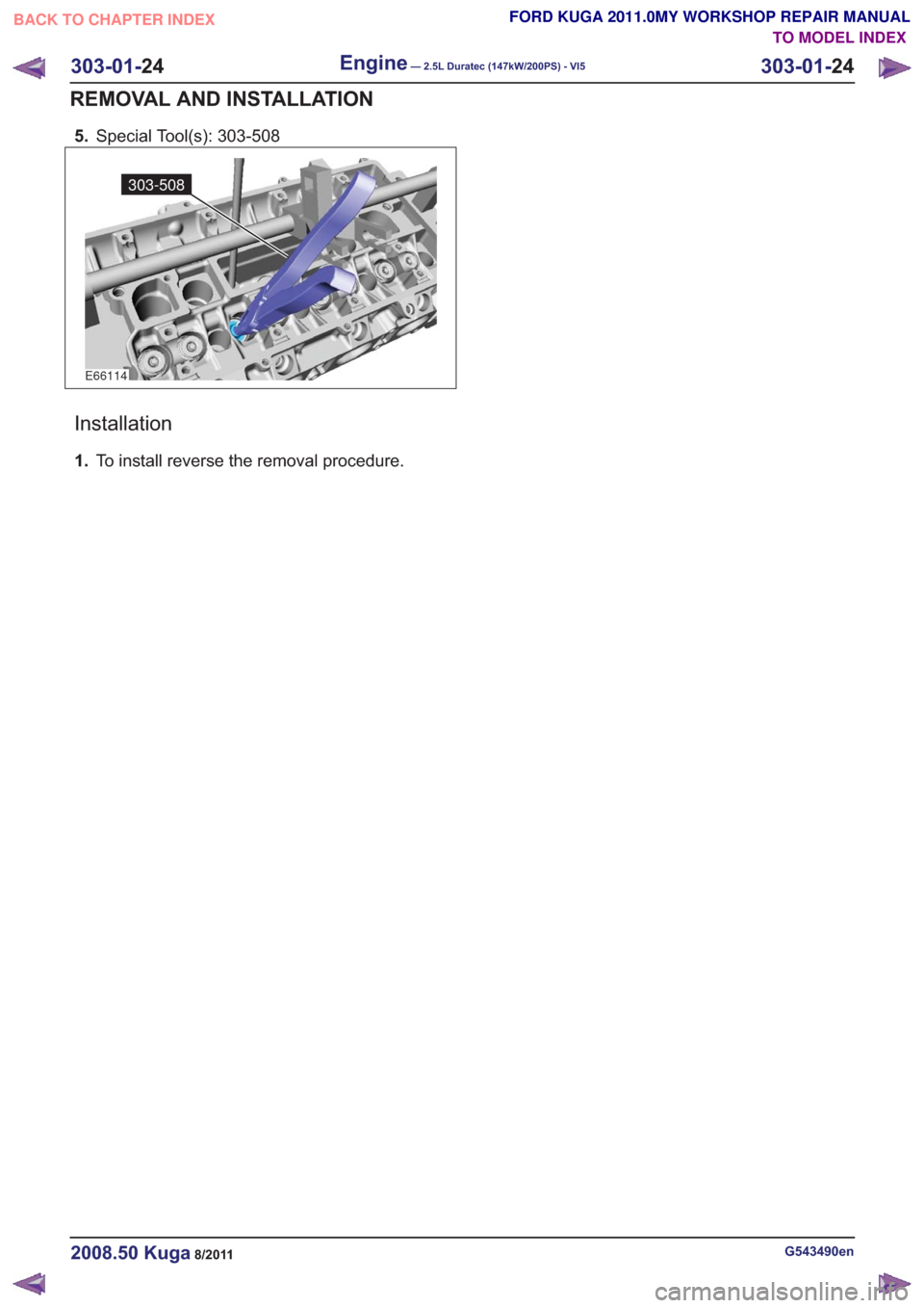
5.Special Tool(s): 303-508
E66114
303-508
Installation
1.To install reverse the removal procedure.
G543490en2008.50 Kuga8/2011
303-01- 24
Engine— 2.5L Duratec (147kW/200PS) - VI5303-01-
24
REMOVAL AND INSTALLATION
TO MODEL INDEX
BACK TO CHAPTER INDEX
FORD KUGA 2011.0MY WORKSHOP REPAIR MANUAL
Page 1558 of 2057
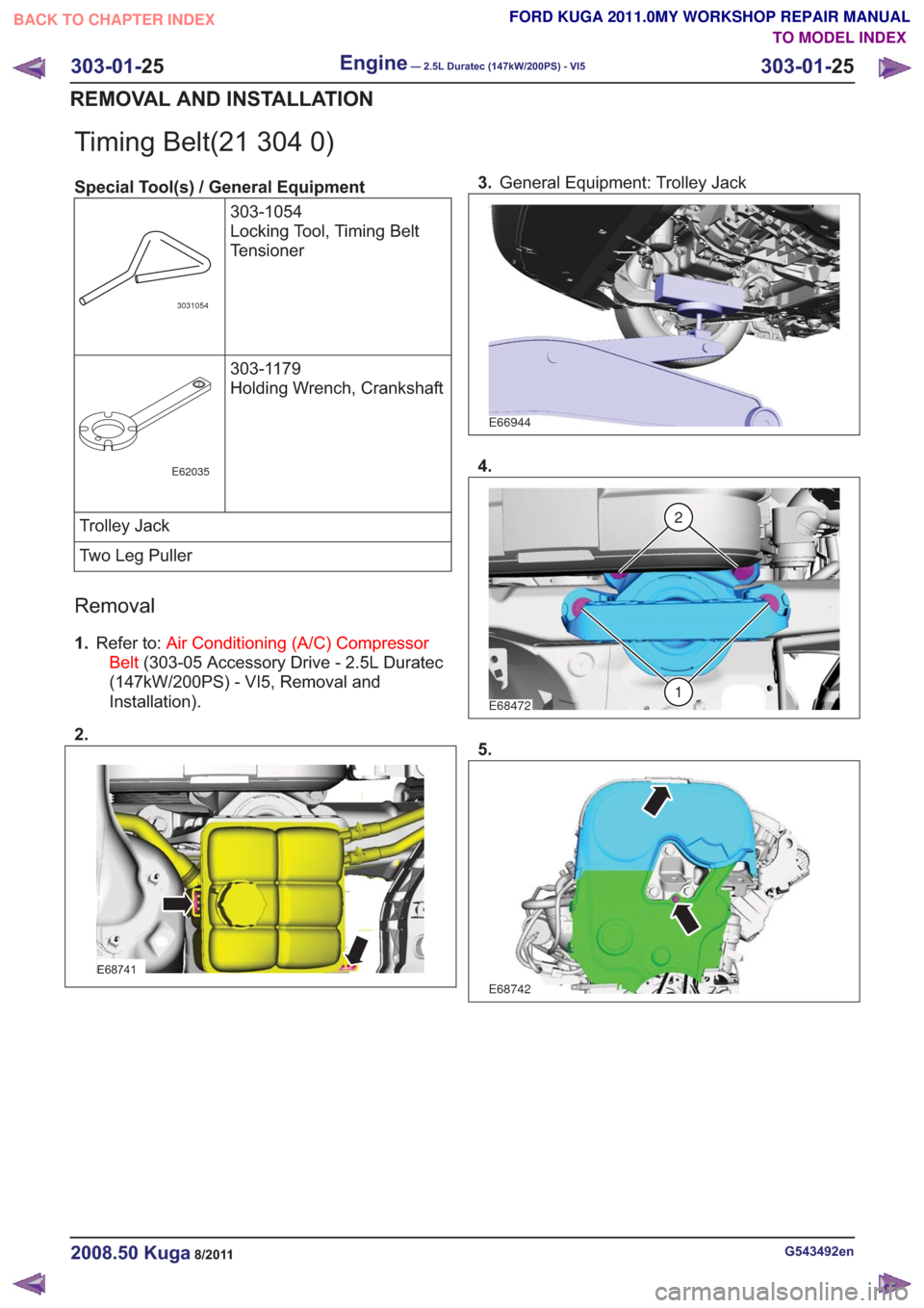
Timing Belt(21 304 0)
Special Tool(s) / General Equipment303-1054
Locking Tool, Timing Belt
Tensioner
3031054
303-1179
Holding Wrench, Crankshaft
E62035
Trolley Jack
Two Leg Puller
Removal
1.Refer to: Air Conditioning (A/C) Compressor
Belt (303-05 Accessory Drive - 2.5L Duratec
(147kW/200PS) - VI5, Removal and
Installation).
2.
E68741
3. General Equipment: Trolley Jack
E66944
4.
E68472
2
1
5.
E68742
G543492en2008.50 Kuga8/2011
303-01- 25
Engine— 2.5L Duratec (147kW/200PS) - VI5303-01-
25
REMOVAL AND INSTALLATION
TO MODEL INDEX
BACK TO CHAPTER INDEX
FORD KUGA 2011.0MY WORKSHOP REPAIR MANUAL
Page 1559 of 2057
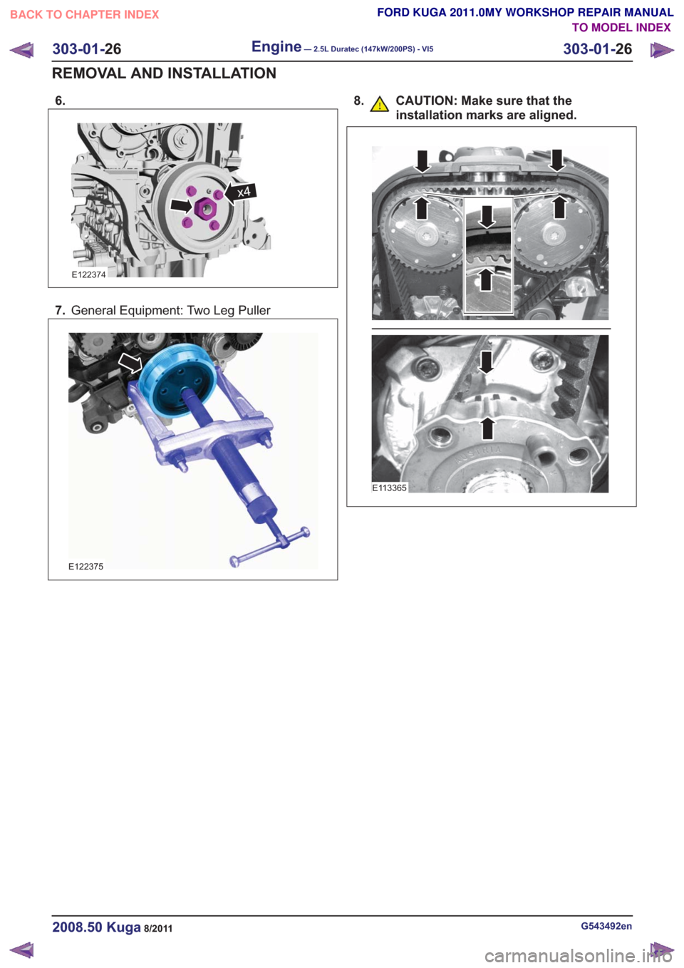
6.
E122374
x4
7.General Equipment: Two Leg Puller
E122375
8. CAUTION: Make sure that the
installation marks are aligned.
E113365
G543492en2008.50 Kuga8/2011
303-01- 26
Engine— 2.5L Duratec (147kW/200PS) - VI5303-01-
26
REMOVAL AND INSTALLATION
TO MODEL INDEX
BACK TO CHAPTER INDEX
FORD KUGA 2011.0MY WORKSHOP REPAIR MANUAL
Page 1560 of 2057
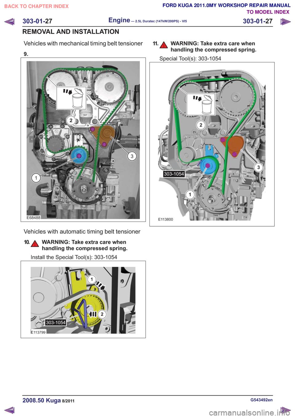
Vehicles with mechanical timing belt tensioner
9.
E68488
1
3
2
Vehicles with automatic timing belt tensioner
10. WARNING: Take extra care whenhandling the compressed spring.
Install the Special Tool(s): 303-1054
1
2
E113799
303-1054
11. WARNING: Take extra care whenhandling the compressed spring.
Special Tool(s): 303-1054
E113800
1
2
3
303-1054
G543492en2008.50 Kuga8/2011
303-01- 27
Engine— 2.5L Duratec (147kW/200PS) - VI5303-01-
27
REMOVAL AND INSTALLATION
TO MODEL INDEX
BACK TO CHAPTER INDEX
FORD KUGA 2011.0MY WORKSHOP REPAIR MANUAL
Trending: 206-05, KUGA PCM, sport mode, Egr, Engine DTC, Central locking, navigation

