jacking FORD KUGA 2011 1.G Owner's Manual
[x] Cancel search | Manufacturer: FORD, Model Year: 2011, Model line: KUGA, Model: FORD KUGA 2011 1.GPages: 2057
Page 1355 of 2057
too close to the fluid level indicator assembly,
or float assembly damage.
Bypass Condition Test
1. Check the fluid in the brake master cylinderreservoir. Fill the brake master cylinder reservoir
if low or empty.
2. Observe the fluid level in the brake master cylinder reservoir. If after several brake
applications, the fluid level remains the same,
measure the wheel turning torque required to
rotate the wheels with the brakes applied as
follows:
Place the transaxle in the NEUTRAL position.
Raise and support the vehicle. REFER to: (100-02
Jacking and Lifting) Jacking (Description and Operation),
Lifting (Description and Operation).
Apply the brakes with a minimum of 445 N (100
lb) and hold for approximately 15 seconds. With
the brakes still applied, exert a torque on the front
wheels of 10.1 Nm (75 lb ft). If either wheel rotates,
install a new brake master cylinder.
REFER to: Brake Master Cylinder - 2.5L Duratec
(147kW/200PS) - VI5 (206-06 Hydraulic Brake
Actuation, Removal and Installation).
Non-Pressure Leaks
Any empty brake master cylinder reservoir
condition may be caused by two types of
non-pressure external leaks.
Type 1: An external leak may occur at the brake
master cylinder reservoir cap because of incorrect
positioning of the gasket and cap. Reposition the
cap and gasket.
Type 2: An external leak may occur at the brake
master cylinder reservoir mounting seals. Service
such a leak by installing new seals.
G1058975en2008.50 Kuga8/2011
206-00- 19
Brake System - General Information
206-00- 19
DIAGNOSIS AND TESTING
TO MODEL INDEX
BACK TO CHAPTER INDEX
FORD KUGA 2011.0MY WORKSHOP REPAIR MANUAL
Page 1368 of 2057
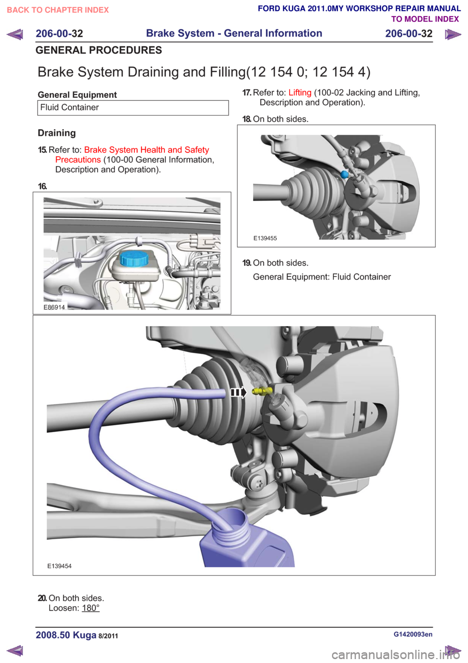
Brake System Draining and Filling(12 154 0; 12 154 4)
General EquipmentFluid Container
Draining
15. Refer to: Brake System Health and Safety
Precautions (100-00 General Information,
Description and Operation).
16.
E86914
17. Refer to: Lifting(100-02 Jacking and Lifting,
Description and Operation).
18. On both sides.
E139455
19.On both sides.
General Equipment: Fluid Container
E139454
20.On both sides.
Loosen: 180°
G1420093en2008.50 Kuga8/2011
206-00- 32
Brake System - General Information
206-00- 32
GENERAL PROCEDURES
TO MODEL INDEX
BACK TO CHAPTER INDEX
FORD KUGA 2011.0MY WORKSHOP REPAIR MANUAL
Page 1388 of 2057
Pinpoint Tests
PINPOINT TEST A : THE PARKING BRAKE WILL NOT APPLY
DETAILS/RESULTS/ACTIONS
TEST CONDITIONS
A1: CHECK PARKING BRAKE CABLE ADJUSTMENT
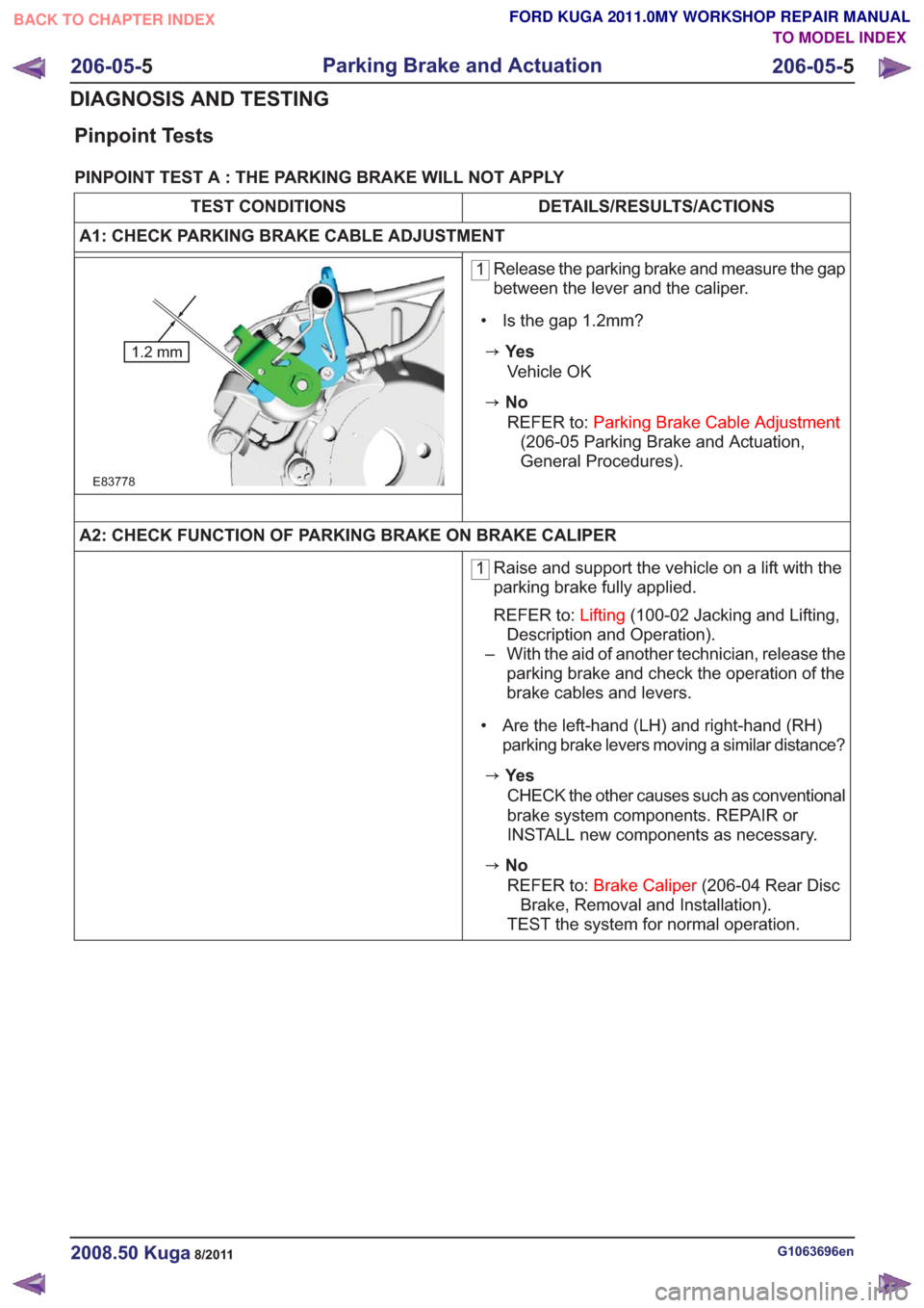
1 Release the parking brake and measure the gap
between the lever and the caliper.
• Is the gap 1.2mm?
zYe s
E83778
1.2 mm
Vehicle OK
zNo REFER to: Parking Brake Cable Adjustment
(206-05 Parking Brake and Actuation,
General Procedures).
A2: CHECK FUNCTION OF PARKING BRAKE ON BRAKE CALIPER
1 Raise and support the vehicle on a lift with the
parking brake fully applied.
REFER to:
Lifting(100-02 Jacking and Lifting,
Description and Operation).
– With the aid of another technician, release the parking brake and check the operation of the
brake cables and levers.
• Are the left-hand (LH) and right-hand (RH) parking brake levers moving a similar distance?
zYe s
CHECK the other causes such as conventional
brake system components. REPAIR or
INSTALL new components as necessary.
zNoREFER to: Brake Caliper (206-04 Rear Disc
Brake, Removal and Installation).
TEST the system for normal operation.
G1063696en2008.50 Kuga8/2011
206-05- 5
Parking Brake and Actuation
206-05- 5
DIAGNOSIS AND TESTING
TO MODEL INDEX
BACK TO CHAPTER INDEX
FORD KUGA 2011.0MY WORKSHOP REPAIR MANUAL
Page 1393 of 2057
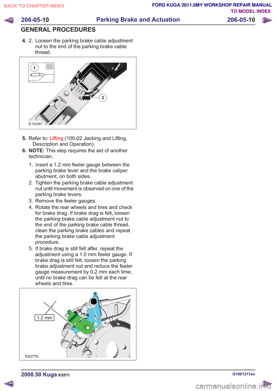
4.Loosen the parking brake cable adjustment
nut to the end of the parking brake cable
thread.
2.
E102067
2
P1
5.
Refer to: Lifting(100-02 Jacking and Lifting,
Description and Operation).
6. NOTE: This step requires the aid of another
technician.
1. Insert a 1.2 mm feeler gauge between the parking brake lever and the brake caliper
abutment, on both sides.
2. Tighten the parking brake cable adjustment nut until movement is observed on one of the
parking brake levers.
3. Remove the feeler gauges.
4. Rotate the rear wheels and tires and check for brake drag. If brake drag is felt, loosen
the parking brake cable adjustment nut to
the end of the parking brake cable thread,
clean the parking brake cables and repeat
the parking brake cable adjustment
procedure.
5. If brake drag is still felt after, repeat the adjustment using a 1.0 mm feeler gauge. If
brake drag is still felt, loosen the parking
brake adjustment nut and reduce the feeler
gauge measurement by 0.2 mm each time,
until no brake drag can be felt at the rear
wheels and tires.
E83778
1.2 mm
G1001211en2008.50 Kuga8/2011
206-05- 10
Parking Brake and Actuation
206-05- 10
GENERAL PROCEDURES
TO MODEL INDEX
BACK TO CHAPTER INDEX
FORD KUGA 2011.0MY WORKSHOP REPAIR MANUAL
Page 1406 of 2057
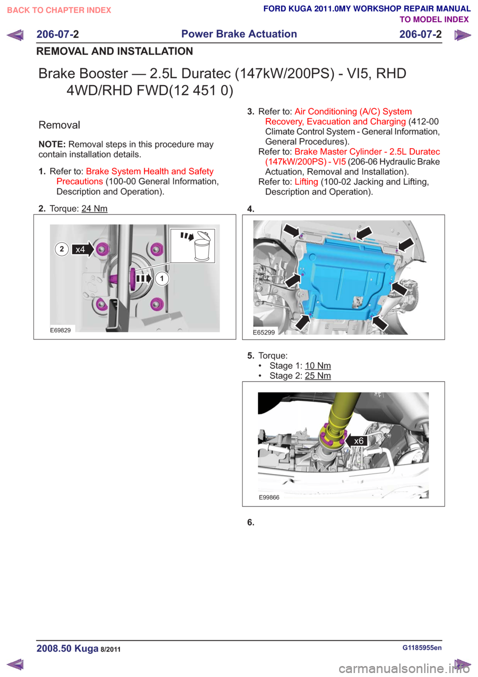
Brake Booster — 2.5L Duratec (147kW/200PS) - VI5, RHD4WD/RHD FWD(12 451 0)
Removal
NOTE: Removal steps in this procedure may
contain installation details.
1. Refer to: Brake System Health and Safety
Precautions (100-00 General Information,
Description and Operation).
2. Torque: 24
Nm
E69829
x4
1
2
3.Refer to: Air Conditioning (A/C) System
Recovery, Evacuation and Charging (412-00
Climate Control System - General Information,
General Procedures).
Refer to: Brake Master Cylinder - 2.5L Duratec
(147kW/200PS) - VI5 (206-06 Hydraulic Brake
Actuation, Removal and Installation).
Refer to: Lifting(100-02 Jacking and Lifting,
Description and Operation).
4.
E65299
5. Torque:
• Stage 1: 10
Nm
• Stage 2: 25Nm
E99866
x6
6.
G1185955en2008.50 Kuga8/2011
206-07- 2
Power Brake Actuation
206-07- 2
REMOVAL AND INSTALLATION
TO MODEL INDEX
BACK TO CHAPTER INDEX
FORD KUGA 2011.0MY WORKSHOP REPAIR MANUAL
Page 1444 of 2057
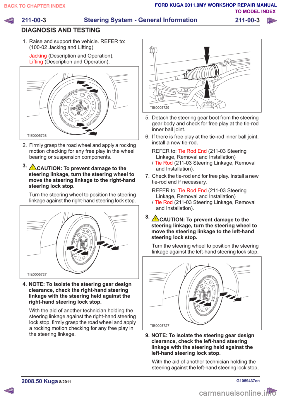
1. Raise and support the vehicle. REFER to:(100-02 Jacking and Lifting)
Jacking (Description and Operation),
Lifting (Description and Operation).
TIE0005728
2. Firmly grasp the road wheel and apply a rocking
motion checking for any free play in the wheel
bearing or suspension components.
3.
CAUTION: To prevent damage to the
steering linkage, turn the steering wheel to
move the steering linkage to the right-hand
steering lock stop.
Turn the steering wheel to position the steering
linkage against the right-hand steering lock stop.
TIE0005727
4. NOTE: To isolate the steering gear design clearance, check the right-hand steering
linkage with the steering held against the
right-hand steering lock stop.
With the aid of another technician holding the
steering linkage against the right-hand steering
lock stop, firmly grasp the road wheel and apply
a rocking motion checking for any free play in
the steering linkage.
TIE0005729
5. Detach the steering gear boot from the steering gear body and check for free play at the tie-rod
inner ball joint.
6. If there is free play at the tie-rod inner ball joint, install a new tie-rod.
REFER to: Tie Rod End (211-03 Steering
Linkage, Removal and Installation)
/ Tie Rod (211-03 Steering Linkage, Removal
and Installation).
7. Check the tie-rod end for free play. Install a new tie-rod end if necessary.
REFER to: Tie Rod End (211-03 Steering
Linkage, Removal and Installation)
/ Tie Rod (211-03 Steering Linkage, Removal
and Installation).
8.
CAUTION: To prevent damage to the
steering linkage, turn the steering wheel to
move the steering linkage to the left-hand
steering lock stop.
Turn the steering wheel to position the steering
linkage against the left-hand steering lock stop.
TIE0005727
9. NOTE: To isolate the steering gear design clearance, check the left-hand steering
linkage with the steering held against the
left-hand steering lock stop.
With the aid of another technician holding the
steering against the left-hand steering lock stop,
G1059437en2008.50 Kuga8/2011
211-00- 3
Steering System - General Information
211-00- 3
DIAGNOSIS AND TESTING
TO MODEL INDEX
BACK TO CHAPTER INDEX
FORD KUGA 2011.0MY WORKSHOP REPAIR MANUAL
Page 1447 of 2057
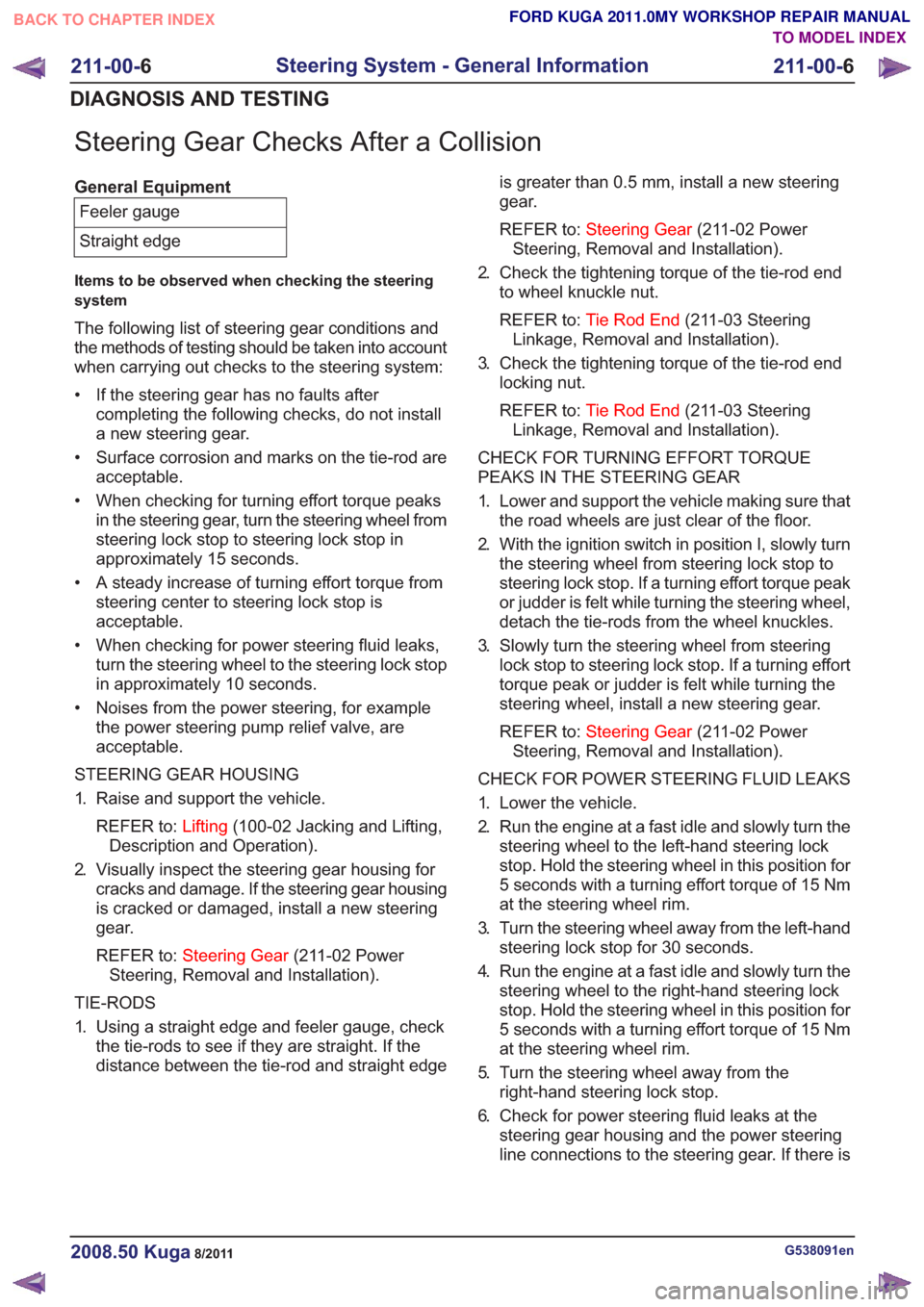
Steering Gear Checks After a Collision
General EquipmentFeeler gauge
Straight edge
Items to be observed when checking the steering
system
The following list of steering gear conditions and
the methods of testing should be taken into account
when carrying out checks to the steering system:
• If the steering gear has no faults after completing the following checks, do not install
a new steering gear.
• Surface corrosion and marks on the tie-rod are acceptable.
• When checking for turning effort torque peaks in the steering gear, turn the steering wheel from
steering lock stop to steering lock stop in
approximately 15 seconds.
• A steady increase of turning effort torque from steering center to steering lock stop is
acceptable.
• When checking for power steering fluid leaks, turn the steering wheel to the steering lock stop
in approximately 10 seconds.
• Noises from the power steering, for example the power steering pump relief valve, are
acceptable.
STEERING GEAR HOUSING
1. Raise and support the vehicle. REFER to: Lifting(100-02 Jacking and Lifting,
Description and Operation).
2. Visually inspect the steering gear housing for cracks and damage. If the steering gear housing
is cracked or damaged, install a new steering
gear.
REFER to: Steering Gear (211-02 Power
Steering, Removal and Installation).
TIE-RODS
1. Using a straight edge and feeler gauge, check the tie-rods to see if they are straight. If the
distance between the tie-rod and straight edge is greater than 0.5 mm, install a new steering
gear.
REFER to:
Steering Gear (211-02 Power
Steering, Removal and Installation).
2. Check the tightening torque of the tie-rod end to wheel knuckle nut.
REFER to: Tie Rod End (211-03 Steering
Linkage, Removal and Installation).
3. Check the tightening torque of the tie-rod end locking nut.
REFER to: Tie Rod End (211-03 Steering
Linkage, Removal and Installation).
CHECK FOR TURNING EFFORT TORQUE
PEAKS IN THE STEERING GEAR
1. Lower and support the vehicle making sure that the road wheels are just clear of the floor.
2. With the ignition switch in position I, slowly turn the steering wheel from steering lock stop to
steering lock stop. If a turning effort torque peak
or judder is felt while turning the steering wheel,
detach the tie-rods from the wheel knuckles.
3. Slowly turn the steering wheel from steering lock stop to steering lock stop. If a turning effort
torque peak or judder is felt while turning the
steering wheel, install a new steering gear.
REFER to: Steering Gear (211-02 Power
Steering, Removal and Installation).
CHECK FOR POWER STEERING FLUID LEAKS
1. Lower the vehicle.
2. Run the engine at a fast idle and slowly turn the steering wheel to the left-hand steering lock
stop. Hold the steering wheel in this position for
5 seconds with a turning effort torque of 15 Nm
at the steering wheel rim.
3. Turn the steering wheel away from the left-hand steering lock stop for 30 seconds.
4. Run the engine at a fast idle and slowly turn the steering wheel to the right-hand steering lock
stop. Hold the steering wheel in this position for
5 seconds with a turning effort torque of 15 Nm
at the steering wheel rim.
5. Turn the steering wheel away from the right-hand steering lock stop.
6. Check for power steering fluid leaks at the steering gear housing and the power steering
line connections to the steering gear. If there is
G538091en2008.50 Kuga8/2011
211-00- 6
Steering System - General Information
211-00- 6
DIAGNOSIS AND TESTING
TO MODEL INDEX
BACK TO CHAPTER INDEX
FORD KUGA 2011.0MY WORKSHOP REPAIR MANUAL
Page 1449 of 2057
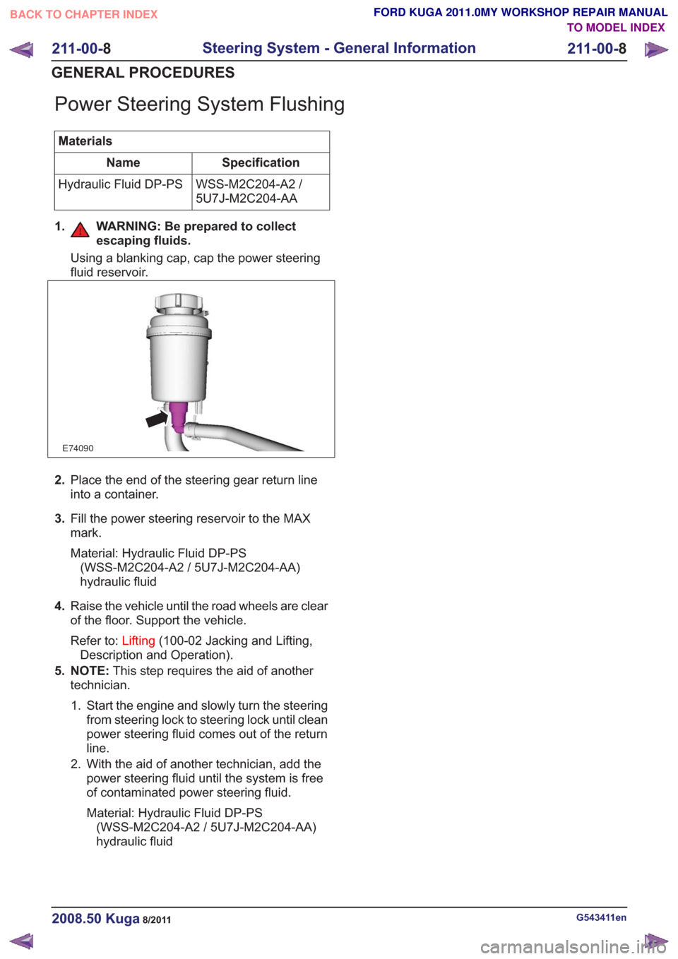
Power Steering System Flushing
MaterialsSpecification
Name
WSS-M2C204-A2 /
5U7J-M2C204-AA
Hydraulic Fluid DP-PS
1. WARNING: Be prepared to collect escaping fluids.
Using a blanking cap, cap the power steering
fluid reservoir.
E74090
2.Place the end of the steering gear return line
into a container.
3. Fill the power steering reservoir to the MAX
mark.
Material: Hydraulic Fluid DP-PS
(WSS-M2C204-A2 / 5U7J-M2C204-AA)
hydraulic fluid
4. Raise the vehicle until the road wheels are clear
of the floor. Support the vehicle.
Refer to: Lifting(100-02 Jacking and Lifting,
Description and Operation).
5. NOTE: This step requires the aid of another
technician.
1. Start the engine and slowly turn the steering from steering lock to steering lock until clean
power steering fluid comes out of the return
line.
2. With the aid of another technician, add the power steering fluid until the system is free
of contaminated power steering fluid.
Material: Hydraulic Fluid DP-PS(WSS-M2C204-A2 / 5U7J-M2C204-AA)
hydraulic fluid
G543411en2008.50 Kuga8/2011
211-00- 8
Steering System - General Information
211-00- 8
GENERAL PROCEDURES
TO MODEL INDEX
BACK TO CHAPTER INDEX
FORD KUGA 2011.0MY WORKSHOP REPAIR MANUAL
Page 1450 of 2057
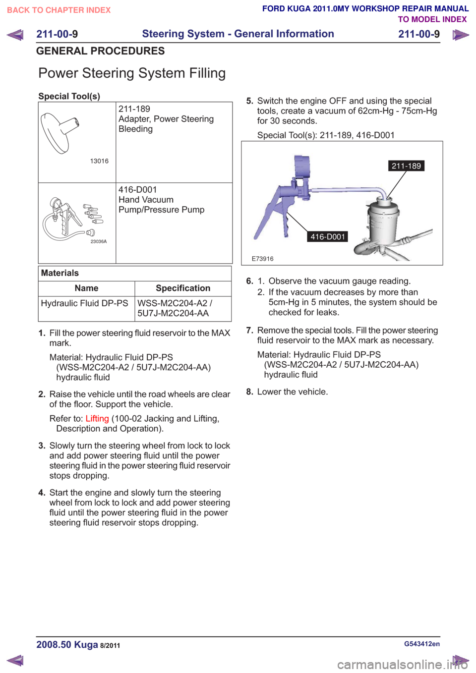
Power Steering System Filling
Special Tool(s)211-189
Adapter, Power Steering
Bleeding
13016
416-D001
Hand Vacuum
Pump/Pressure Pump
23036A
Materials
Specification
Name
WSS-M2C204-A2 /
5U7J-M2C204-AA
Hydraulic Fluid DP-PS
1. Fill the power steering fluid reservoir to the MAX
mark.
Material: Hydraulic Fluid DP-PS
(WSS-M2C204-A2 / 5U7J-M2C204-AA)
hydraulic fluid
2. Raise the vehicle until the road wheels are clear
of the floor. Support the vehicle.
Refer to: Lifting(100-02 Jacking and Lifting,
Description and Operation).
3. Slowly turn the steering wheel from lock to lock
and add power steering fluid until the power
steering fluid in the power steering fluid reservoir
stops dropping.
4. Start the engine and slowly turn the steering
wheel from lock to lock and add power steering
fluid until the power steering fluid in the power
steering fluid reservoir stops dropping. 5.
Switch the engine OFF and using the special
tools, create a vacuum of 62cm-Hg - 75cm-Hg
for 30 seconds.
Special Tool(s): 211-189, 416-D001
E73916
211-189
416-D001
6. Observe the vacuum gauge reading.
1.
2. If the vacuum decreases by more than
5cm-Hg in 5 minutes, the system should be
checked for leaks.
7. Remove the special tools. Fill the power steering
fluid reservoir to the MAX mark as necessary.
Material: Hydraulic Fluid DP-PS
(WSS-M2C204-A2 / 5U7J-M2C204-AA)
hydraulic fluid
8. Lower the vehicle.
G543412en2008.50 Kuga8/2011
211-00- 9
Steering System - General Information
211-00- 9
GENERAL PROCEDURES
TO MODEL INDEX
BACK TO CHAPTER INDEX
FORD KUGA 2011.0MY WORKSHOP REPAIR MANUAL
Page 1527 of 2057
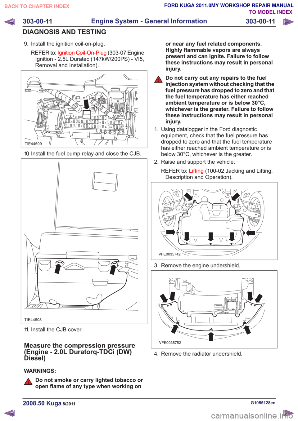
9. Install the ignition coil-on-plug.REFER to: Ignition Coil-On-Plug (303-07 Engine
Ignition - 2.5L Duratec (147kW/200PS) - VI5,
Removal and Installation).
TIE44609
10. Install the fuel pump relay and close the CJB.
TIE44608
11. Install the CJB cover.
Measure the compression pressure
(Engine - 2.0L Duratorq-TDCi (DW)
Diesel)
WARNINGS:
Do not smoke or carry lighted tobacco or
open flame of any type when working on or near any fuel related components.
Highly flammable vapors are always
present and can ignite. Failure to follow
these instructions may result in personal
injury.
Do not carry out any repairs to the fuel
injection system without checking that the
fuel pressure has dropped to zero and that
the fuel temperature has either reached
ambient temperature or is below 30°C,
whichever is the greater. Failure to follow
these instructions may result in personal
injury.
1. Using datalogger in the Ford diagnostic
equipment , check that the fuel pressure has
dropped to zero and that the fuel temperature
has either reached ambient temperature or is
below 30°C, whichever is the greater.
2. Raise and support the vehicle.
REFER to: Lifting(100-02 Jacking and Lifting,
Description and Operation).
VFE0035742
3. Remove the engine undershield.
VFE0035752
4. Remove the radiator undershield.
G1055128en2008.50 Kuga8/2011
303-00- 11
Engine System - General Information
303-00- 11
DIAGNOSIS AND TESTING
TO MODEL INDEX
BACK TO CHAPTER INDEX
FORD KUGA 2011.0MY WORKSHOP REPAIR MANUAL