Abs sensor FORD KUGA 2011 1.G Owner's Guide
[x] Cancel search | Manufacturer: FORD, Model Year: 2011, Model line: KUGA, Model: FORD KUGA 2011 1.GPages: 2057
Page 1807 of 2057
Description
Item
Coil-on-plug ignition coil
1
Spark plug connector
2
Low-voltage connection
3
Laminated soft-iron core
4Description
Item
Primary winding
5
Secondary winding
6
Spark plug
7
High-voltage connection via spring contact
8
In an ignition system with coil-on-plug ignition coils,
each cylinder is actuated individually and only once
per cycle (working stroke). The coil-on-plug ignition
coils are mounted directly on the spark plugs,
therefore no ignition cables are required between
the ignition coils and the spark plugs.
Each individual ignition coil is actuated on the
low-voltage side by the PCM. The power
end-stages are incorporated into the coil-on-plug
ignition coils. Only the actuating current for these
power end-stages is controlled by the PCM.
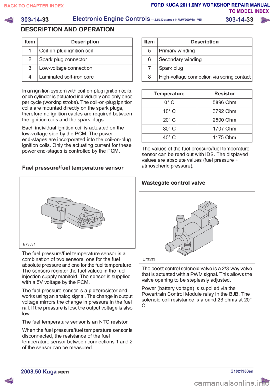
Fuel pressure/fuel temperature sensor
E73531
The fuel pressure/fuel temperature sensor is a
combination of two sensors, one for the fuel
absolute pressure and one for the fuel temperature.
The sensors register the fuel values in the fuel
injection supply manifold. The sensor is supplied
with a 5V voltage by the PCM.
The fuel pressure sensor is a piezoresistor and
works using an analog signal. The change in output
voltage mirrors the change in pressure in the fuel
rail. If the pressure is low, the output voltage is also
low.
The fuel temperature sensor is an NTC resistor.
When the fuel pressure/fuel temperature sensor is
disconnected, the resistance of the fuel
temperature sensor between connections 1 and 2
of the sensor can be measured.
Resistor
Temperature
5896 Ohm
0° C
3792 Ohm
10° C
2500 Ohm
20° C
1707 Ohm
30° C
1175 Ohm
40° C
The values of the fuel pressure/fuel temperature
sensor can be read out with IDS. The displayed
values are absolute values (fuel pressure +
atmospheric pressure).
Wastegate control valve
E73539
The boost control solenoid valve is a 2/3-way valve
that is actuated with a PWM signal. This allows the
valve opening to be steplessly adjusted.
Power (battery voltage) is supplied via the
Powertrain Control Module relay in the BJB. The
solenoid coil resistance is around 23 ohms at 20°
C.
G1021908en2008.50 Kuga8/2011
303-14- 33
Electronic Engine Controls— 2.5L Duratec (147kW/200PS) - VI5303-14-
33
DESCRIPTION AND OPERATION
TO MODEL INDEX
BACK TO CHAPTER INDEX
FORD KUGA 2011.0MY WORKSHOP REPAIR MANUAL
Page 1835 of 2057
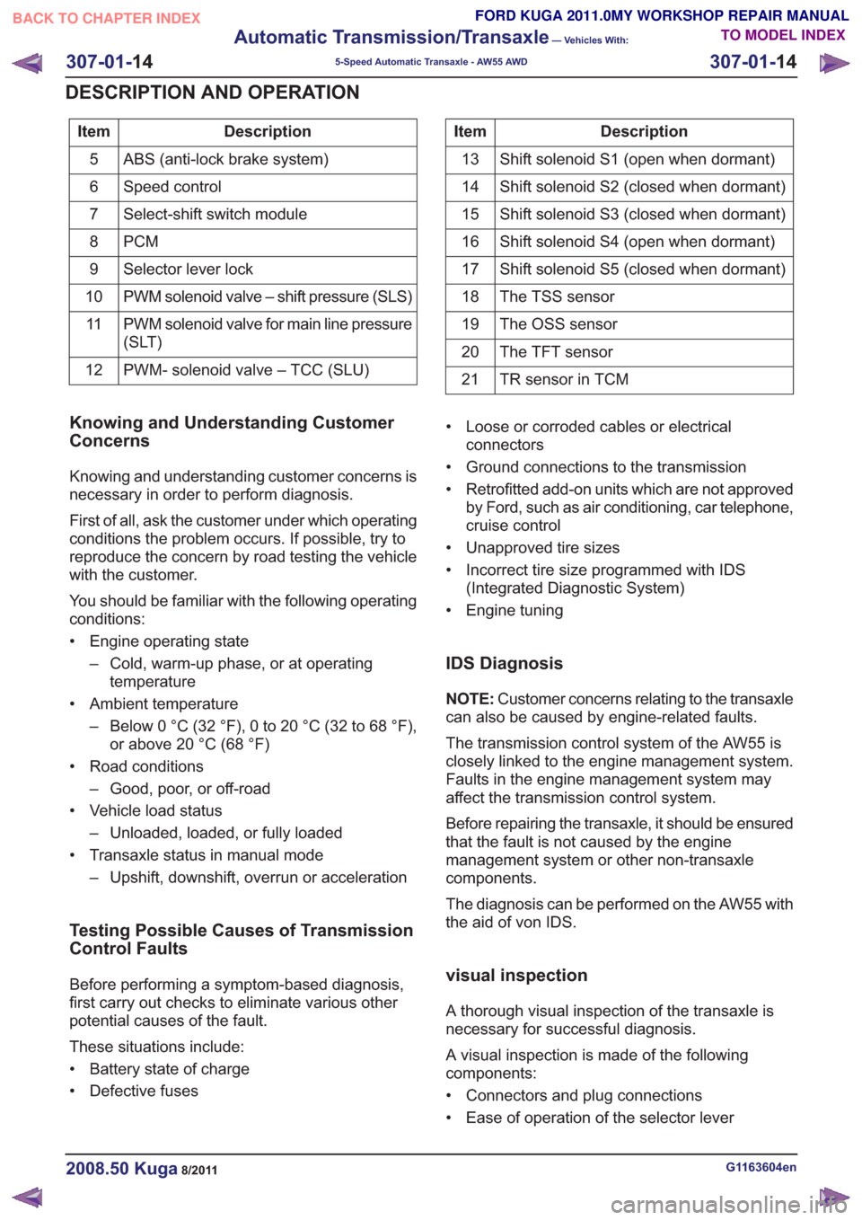
Description
Item
ABS (anti-lock brake system)
5
Speed control
6
Select-shift switch module
7
PCM
8
Selector lever lock
9
PWM solenoid valve – shift pressure (SLS)
10
PWM solenoid valve for main line pressure
(SLT)
11
PWM- solenoid valve – TCC (SLU)
12Description
Item
Shift solenoid S1 (open when dormant)
13
Shift solenoid S2 (closed when dormant)
14
Shift solenoid S3 (closed when dormant)
15
Shift solenoid S4 (open when dormant)
16
Shift solenoid S5 (closed when dormant)
17
The TSS sensor
18
The OSS sensor
19
The TFT sensor
20
TR sensor in TCM
21
Knowing and Understanding Customer
Concerns
Knowing and understanding customer concerns is
necessary in order to perform diagnosis.
First of all, ask the customer under which operating
conditions the problem occurs. If possible, try to
reproduce the concern by road testing the vehicle
with the customer.
You should be familiar with the following operating
conditions:
• Engine operating state
– Cold, warm-up phase, or at operatingtemperature
• Ambient temperature – Below 0 °C (32 °F), 0 to 20 °C (32 to 68 °F),or above 20 °C (68 °F)
• Road conditions – Good, poor, or off-road
• Vehicle load status – Unloaded, loaded, or fully loaded
• Transaxle status in manual mode – Upshift, downshift, overrun or acceleration
Testing Possible Causes of Transmission
Control Faults
Before performing a symptom-based diagnosis,
first carry out checks to eliminate various other
potential causes of the fault.
These situations include:
• Battery state of charge
• Defective fuses • Loose or corroded cables or electrical
connectors
• Ground connections to the transmission
• Retrofitted add-on units which are not approved by Ford, such as air conditioning, car telephone,
cruise control
• Unapproved tire sizes
• Incorrect tire size programmed with IDS (Integrated Diagnostic System)
• Engine tuning
IDS Diagnosis
NOTE: Customer concerns relating to the transaxle
can also be caused by engine-related faults.
The transmission control system of the AW55 is
closely linked to the engine management system.
Faults in the engine management system may
affect the transmission control system.
Before repairing the transaxle, it should be ensured
that the fault is not caused by the engine
management system or other non-transaxle
components.
The diagnosis can be performed on the AW55 with
the aid of von IDS.
visual inspection
A thorough visual inspection of the transaxle is
necessary for successful diagnosis.
A visual inspection is made of the following
components:
• Connectors and plug connections
• Ease of operation of the selector lever
G1163604en2008.50 Kuga8/2011
307-01- 14
Automatic Transmission/Transaxle
— Vehicles With:
5-Speed Automatic Transaxle - AW55 AWD
307-01- 14
DESCRIPTION AND OPERATION
TO MODEL INDEX
BACK TO CHAPTER INDEX
FORD KUGA 2011.0MY WORKSHOP REPAIR MANUAL
Page 1847 of 2057
E112322
The TCM adapts the gear changing to ensure that
the correct gear is selected for the style of driving,
the engine load, driver requirements, vehicle speed
etc. This leads to lower fuel consumption together
with improved comfort through smoother gear
changes and lower noise levels.
The TCM receives information on the driver's
desired transmission range and type of driving
mode. In contrast to a transmission which is only
controlled hydraulically, the control module can
calculate the best times to shift gear and activate
torque converter lockup by using the signals from
the sensors in the transmission and the engine
management system.
The control module enables small changes in the
operating conditions to be made and adapts thevarious transmission functions to ensure that the
correct gear is always selected in relation to the
type of driving mode.
The TCM has adaptive capabilities. This ensures
smooth gear changes throughout the whole service
life of the transmission.
To exactly determine the activation points of the
gear shifts and torque converter lockup on the
basis of the type of driving mode chosen, the TCM
receives the following information:
• Transmission range chosen (TR sensor).
• Type of driving mode chosen
(normal/sport/select-shift).
• Transmission input shaft speed (TSS sensor).
• Transmission output shaft speed (OSS sensor).
• Transmission fluid temperature (TFT sensor).
• The engine speed and the torque as well as the throttle plate opening - from the PCM via the
CAN data bus.
• Actuation of the accelerator pedal - from the PCM via the CAN data bus.
• Coolant temperature - from the PCM via the CAN data bus.
• Vehicle speed - from the ABS via the CAN data bus.
• Actuation of the brake pedal - from the ABS via the CAN data bus.
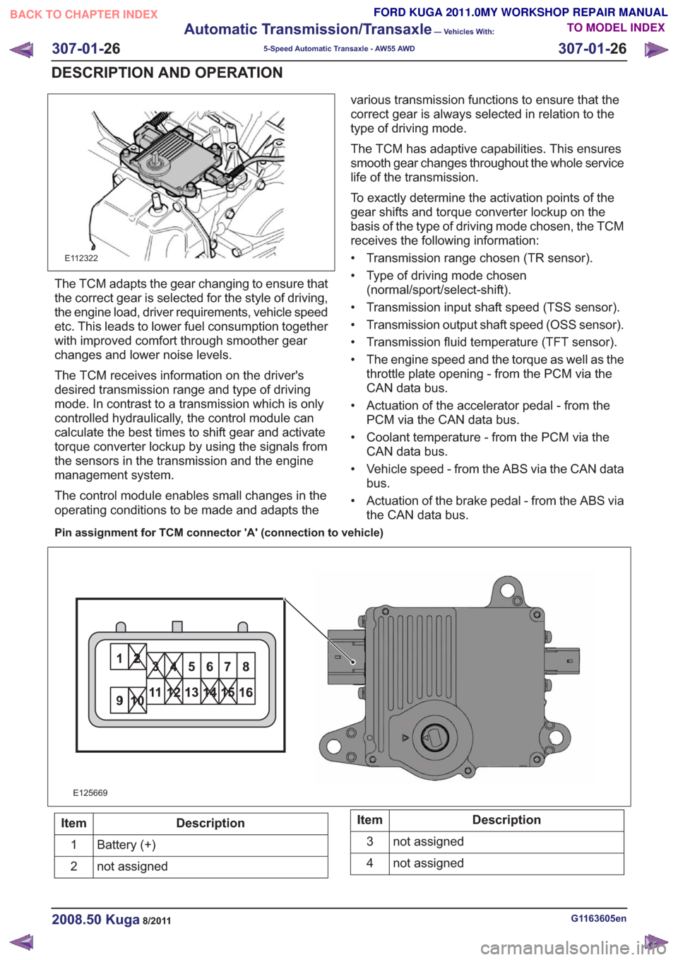
Pin assignment for TCM connector 'A' (connection to vehicle)
11
E125669
Description
Item
Battery (+)
1
not assigned
2Description
Item
not assigned
3
not assigned
4
G1163605en2008.50 Kuga8/2011
307-01- 26
Automatic Transmission/Transaxle
— Vehicles With:
5-Speed Automatic Transaxle - AW55 AWD
307-01- 26
DESCRIPTION AND OPERATION
TO MODEL INDEX
BACK TO CHAPTER INDEX
FORD KUGA 2011.0MY WORKSHOP REPAIR MANUAL
Page 1850 of 2057
To exactly determine the activation points of the
gear shifts and torque converter lockup on the
basis of the type of driving mode chosen, the TCM
receives the following information:
• Selected transmission range (TR sensor)
• Selected driving mode (normal/sport/select-shift)
• Transmission input shaft speed (TSS sensor)
• Transmission output shaft speed (OSS sensor)
• Transmission fluid temperature (TFT sensor)
• The engine speed and the torque as well as thethrottle plate opening - from the PCM via the
CAN databus
• Actuation of accelerator – from the PCM via the CAN databus
• The coolant temperature – from the PCM via the CAN databus
• Road speed – from the ABS module via the CAN databus
• Actuation of brake pedal – from the PCM via the CAN databus
Gearshift control
Adaptation
The TCM monitors every shift operation in all
driving conditions to make even and smooth gear
shifts possible. This is done by the control module,
which either lowers or increases the hydraulic line
pressure during gearshifts.
The changed pressure values are stored in the
control module memory after the engine is switched
off and retrieved during engine starting. This
improves the shift comfort and extends the service
life.
Full adaptability occurs when the following criteria
are met:
• Throttle plate opening is constant.
• Transmission fluid temperature between 65 °Cand 110 °C.
Shifting from 'P' to another transmission
range
To be able to move the selector lever from 'P' into
another transmission range, the ignition must be
switched on and the brake pedal pressed (stoplamp
switch on). The TCM detects the position of the
brake pedal via the CAN data bus and the engaged
transmission range from the TR sensor. Based on this information, the TCM transmits a
signal to the select-shift switch module. This
activates the brake shift interlock actuator in the
selector lever assembly.
When the brake shift interlock actuator is activated,
the locking pin is retracted so that another
transmission range can be selected.
The brake shift interlock actuator is deactivated
when the ignition is switched off. It is mechanically
locked when the gear selector lever is in 'P'.
Automatic transmission, selector lever in
position "D".
The TCM adapts the shift points to match the
driving conditions. Normally the TCM is in adaptive
mode and gear changes take place adapted to the
driving conditions. If special driving conditions are
detected, the TCM switches to predefined
characteristics.
When driving with normal acceleration, the TCM
uses a preset shift program which is optimized for
economical driving.
This shift program is suitable for "normal" driving
and delivers early upward changes and torque
converter lockup. Furthermore, the transmission
fluid pressure is adapted to make smooth
engagement of the gears possible.
Sport mode, selector lever in position "S"
The transmission switches from automatic
operation into sport mode. In this mode the TCM
switches to another set of characteristic curves.
These characteristic curves for control of the gear
changes are adapted to sporting calculations (e.g.
gear change at higher engine speed).
In the sport mode shift program the shift points are
set so that good performance is offered. Changing
down occurs at lower engine speeds.
Manual gear changes (select-shift mode) can be
made in sport mode by moving the selector lever
in the (+) or (-) direction.
Changing gear in select-shift mode
If you move the selector lever to 'S', the automatic
transaxle remains hydraulically in 'D' position. If
you move the gear selector lever forwards (-), the
G1163605en2008.50 Kuga8/2011
307-01-
29
Automatic Transmission/Transaxle
— Vehicles With:
5-Speed Automatic Transaxle - AW55 AWD
307-01- 29
DESCRIPTION AND OPERATION
TO MODEL INDEX
BACK TO CHAPTER INDEX
FORD KUGA 2011.0MY WORKSHOP REPAIR MANUAL
Page 1865 of 2057
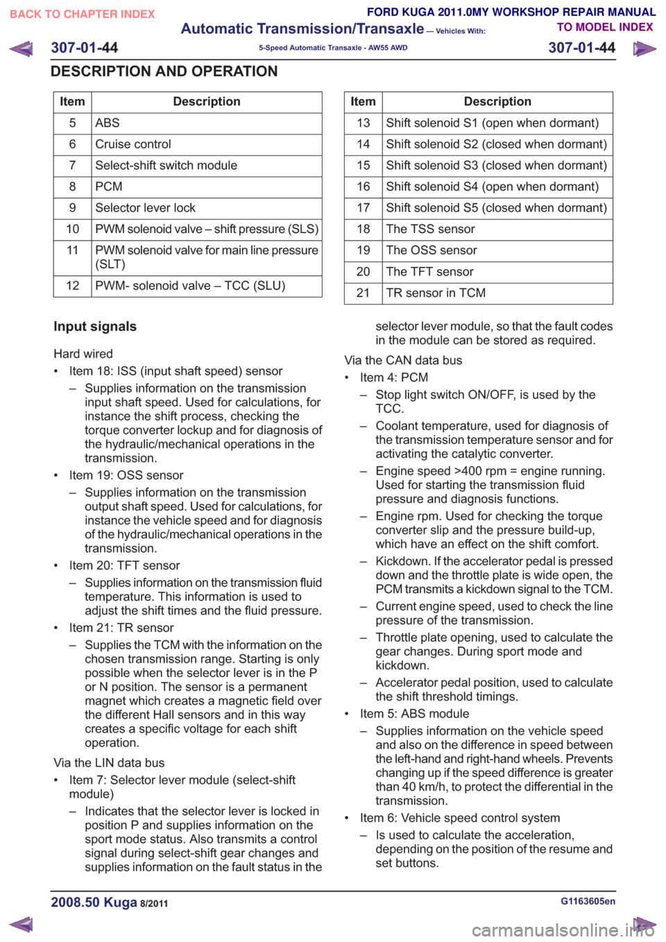
Description
Item
ABS5
Cruise control
6
Select-shift switch module
7
PCM
8
Selector lever lock
9
PWM solenoid valve – shift pressure (SLS)
10
PWM solenoid valve for main line pressure
(SLT)
11
PWM- solenoid valve – TCC (SLU)
12Description
Item
Shift solenoid S1 (open when dormant)
13
Shift solenoid S2 (closed when dormant)
14
Shift solenoid S3 (closed when dormant)
15
Shift solenoid S4 (open when dormant)
16
Shift solenoid S5 (closed when dormant)
17
The TSS sensor
18
The OSS sensor
19
The TFT sensor
20
TR sensor in TCM
21
Input signals
Hard wired
• Item 18: ISS (input shaft speed) sensor
– Supplies information on the transmissioninput shaft speed. Used for calculations, for
instance the shift process, checking the
torque converter lockup and for diagnosis of
the hydraulic/mechanical operations in the
transmission.
• Item 19: OSS sensor – Supplies information on the transmissionoutput shaft speed. Used for calculations, for
instance the vehicle speed and for diagnosis
of the hydraulic/mechanical operations in the
transmission.
• Item 20: TFT sensor – Supplies information on the transmission fluidtemperature. This information is used to
adjust the shift times and the fluid pressure.
• Item 21: TR sensor – Supplies the TCM with the information on thechosen transmission range. Starting is only
possible when the selector lever is in the P
or N position. The sensor is a permanent
magnet which creates a magnetic field over
the different Hall sensors and in this way
creates a specific voltage for each shift
operation.
Via the LIN data bus
• Item 7: Selector lever module (select-shift module)
– Indicates that the selector lever is locked inposition P and supplies information on the
sport mode status. Also transmits a control
signal during select-shift gear changes and
supplies information on the fault status in the selector lever module, so that the fault codes
in the module can be stored as required.
Via the CAN data bus
• Item 4: PCM – Stop light switch ON/OFF, is used by theTCC.
– Coolant temperature, used for diagnosis of the transmission temperature sensor and for
activating the catalytic converter.
– Engine speed >400 rpm = engine running. Used for starting the transmission fluid
pressure and diagnosis functions.
– Engine rpm. Used for checking the torque converter slip and the pressure build-up,
which have an effect on the shift comfort.
– Kickdown. If the accelerator pedal is pressed down and the throttle plate is wide open, the
PCM transmits a kickdown signal to the TCM.
– Current engine speed, used to check the line pressure of the transmission.
– Throttle plate opening, used to calculate the gear changes. During sport mode and
kickdown.
– Accelerator pedal position, used to calculate the shift threshold timings.
• Item 5: ABS module – Supplies information on the vehicle speedand also on the difference in speed between
the left-hand and right-hand wheels. Prevents
changing up if the speed difference is greater
than 40 km/h, to protect the differential in the
transmission.
• Item 6: Vehicle speed control system – Is used to calculate the acceleration,depending on the position of the resume and
set buttons.
G1163605en2008.50 Kuga8/2011
307-01- 44
Automatic Transmission/Transaxle
— Vehicles With:
5-Speed Automatic Transaxle - AW55 AWD
307-01- 44
DESCRIPTION AND OPERATION
TO MODEL INDEX
BACK TO CHAPTER INDEX
FORD KUGA 2011.0MY WORKSHOP REPAIR MANUAL
Page 1879 of 2057
transaxle output shaft. The frequency of the
square-wave signal increases with the speed of
the transmission output shaft.
The OSS sensor picks up the speed at the gear of
the parking lock.
The TCM uses the information from the OSS
sensor for the following parameters:
• Calculation of the degree of torque reductionthat needs to be requested by the PCM during
shifting.
• Calculation of the shift points.
• Calculation of the engaging and disengaging point for the TCC (lock-up function).
• Calculation of the current gear ratios by comparison of the TSS sensor signal.
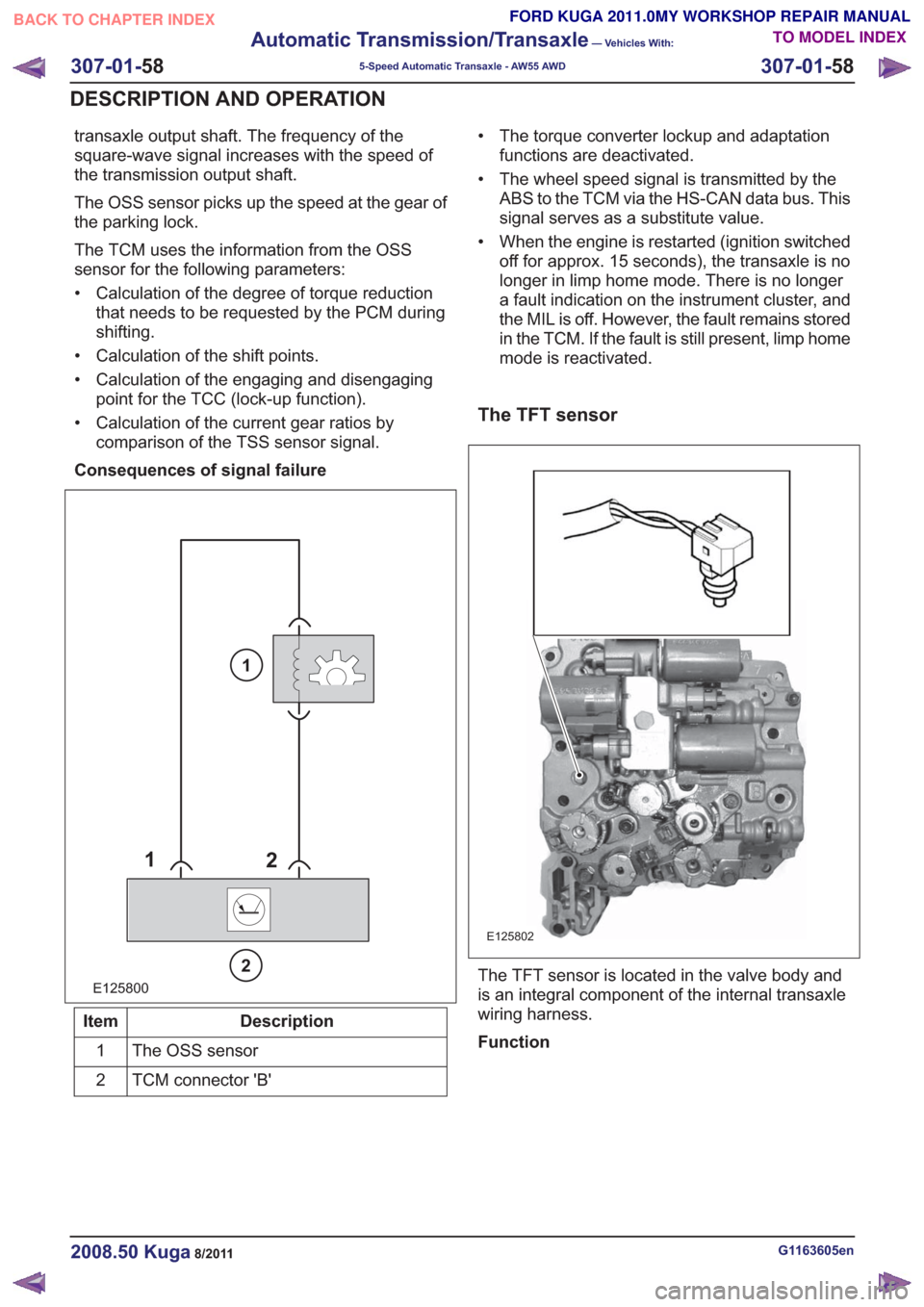
Consequences of signal failure
E125800
1 2
2
1
Description
Item
The OSS sensor
1
TCM connector 'B'
2 • The torque converter lockup and adaptation
functions are deactivated.
• The wheel speed signal is transmitted by the ABS to the TCM via the HS-CAN data bus. This
signal serves as a substitute value.
• When the engine is restarted (ignition switched off for approx. 15 seconds), the transaxle is no
longer in limp home mode. There is no longer
a fault indication on the instrument cluster, and
the MIL is off. However, the fault remains stored
in the TCM. If the fault is still present, limp home
mode is reactivated.
The TFT sensor
E125802
The TFT sensor is located in the valve body and
is an integral component of the internal transaxle
wiring harness.
Function
G1163605en2008.50 Kuga8/2011
307-01- 58
Automatic Transmission/Transaxle
— Vehicles With:
5-Speed Automatic Transaxle - AW55 AWD
307-01- 58
DESCRIPTION AND OPERATION
TO MODEL INDEX
BACK TO CHAPTER INDEX
FORD KUGA 2011.0MY WORKSHOP REPAIR MANUAL
Page 1999 of 2057
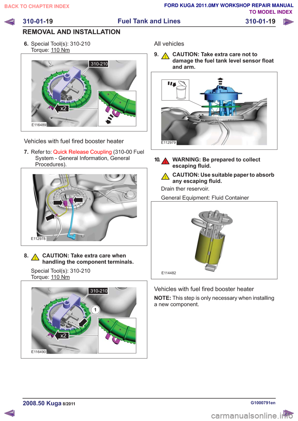
6.Special Tool(s): 310-210
Torque: 1
10Nm
310-210
x2
310-210
x2
E116489
Vehicles with fuel fired booster heater
7.Refer to: Quick Release Coupling (310-00 Fuel
System - General Information, General
Procedures).
E112978
8. CAUTION: Take extra care when handling the component terminals.
Special Tool(s): 310-210
Torque: 1
10Nm
310-210
x2
310-210
x2
E116490
1
All vehicles
9. CAUTION: Take extra care not todamage the fuel tank level sensor float
and arm.
E112979
10. WARNING: Be prepared to collectescaping fluid.
CAUTION: Use suitable paper to absorb
any escaping fluid.
Drain ther reservoir.
General Equipment: Fluid Container
E114482
Vehicles with fuel fired booster heater
NOTE: This step is only necessary when installing
a new component.
G1000791en2008.50 Kuga8/2011
310-01- 19
Fuel Tank and Lines
310-01- 19
REMOVAL AND INSTALLATION
TO MODEL INDEX
BACK TO CHAPTER INDEX
FORD KUGA 2011.0MY WORKSHOP REPAIR MANUAL
Page 2006 of 2057
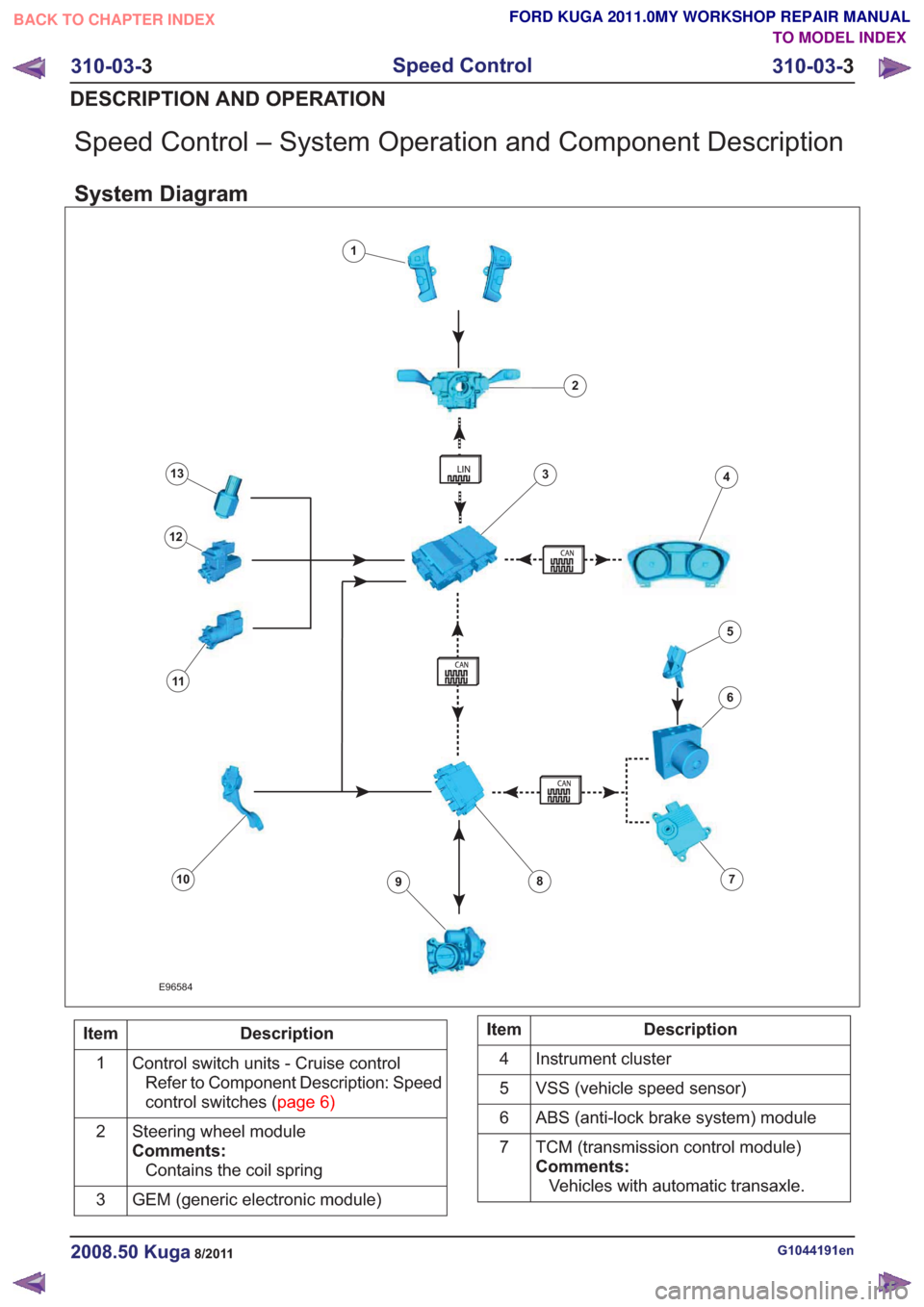
Speed Control – System Operation and Component Description
System Diagram
E96584
1
2
34
6
78910
11
12
13
5
Description
Item
Control switch units - Cruise controlRefer to Component Description: Speed
controlswitches(page6)
1
Steering wheel module
Comments:Contains the coil spring
2
GEM (generic electronic module)
3Description
Item
Instrument cluster
4
VSS (vehicle speed sensor)
5
ABS (anti-lock brake system) module
6
TCM (transmission control module)
Comments:Vehicles with automatic transaxle.
7
G1044191en2008.50 Kuga8/2011
310-03-
3
Speed Control
310-03- 3
DESCRIPTION AND OPERATION
TO MODEL INDEX
BACK TO CHAPTER INDEX
FORD KUGA 2011.0MY WORKSHOP REPAIR MANUAL
Page 2007 of 2057
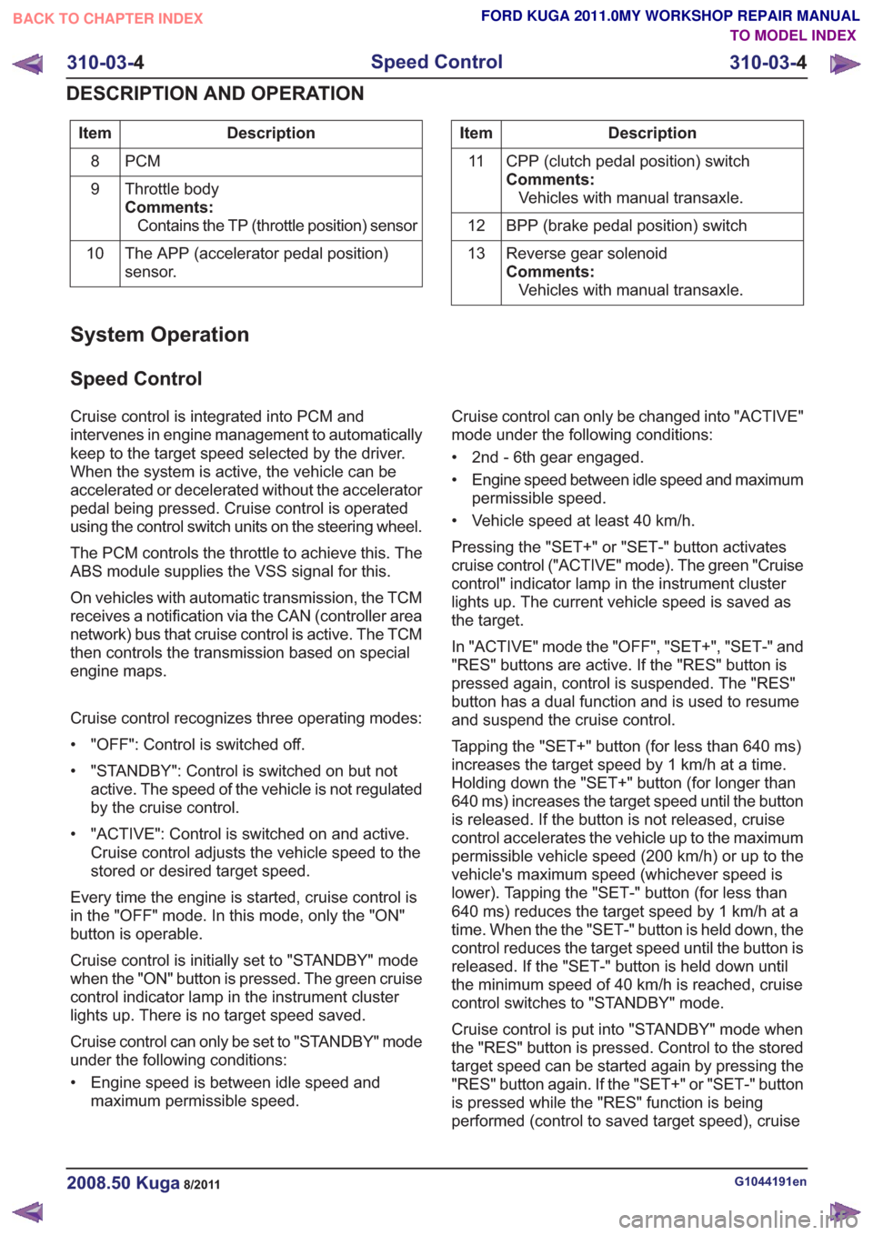
Description
Item
PCM
8
Throttle body
Comments:Contains the TP (throttle position) sensor
9
The APP (accelerator pedal position)
sensor.
10Description
Item
CPP (clutch pedal position) switch
Comments:Vehicles with manual transaxle.
11
BPP (brake pedal position) switch
12
Reverse gear solenoid
Comments:Vehicles with manual transaxle.
13
System Operation
Speed Control
Cruise control is integrated into PCM and
intervenes in engine management to automatically
keep to the target speed selected by the driver.
When the system is active, the vehicle can be
accelerated or decelerated without the accelerator
pedal being pressed. Cruise control is operated
using the control switch units on the steering wheel.
The PCM controls the throttle to achieve this. The
ABS module supplies the VSS signal for this.
On vehicles with automatic transmission, the TCM
receives a notification via the CAN (controller area
network) bus that cruise control is active. The TCM
then controls the transmission based on special
engine maps.
Cruise control recognizes three operating modes:
• "OFF": Control is switched off.
• "STANDBY": Control is switched on but not
active. The speed of the vehicle is not regulated
by the cruise control.
• "ACTIVE": Control is switched on and active. Cruise control adjusts the vehicle speed to the
stored or desired target speed.
Every time the engine is started, cruise control is
in the "OFF" mode. In this mode, only the "ON"
button is operable.
Cruise control is initially set to "STANDBY" mode
when the "ON" button is pressed. The green cruise
control indicator lamp in the instrument cluster
lights up. There is no target speed saved.
Cruise control can only be set to "STANDBY" mode
under the following conditions:
• Engine speed is between idle speed and maximum permissible speed. Cruise control can only be changed into "ACTIVE"
mode under the following conditions:
• 2nd - 6th gear engaged.
• Engine speed between idle speed and maximum
permissible speed.
• Vehicle speed at least 40 km/h.
Pressing the "SET+" or "SET-" button activates
cruise control ("ACTIVE" mode). The green "Cruise
control" indicator lamp in the instrument cluster
lights up. The current vehicle speed is saved as
the target.
In "ACTIVE" mode the "OFF", "SET+", "SET-" and
"RES" buttons are active. If the "RES" button is
pressed again, control is suspended. The "RES"
button has a dual function and is used to resume
and suspend the cruise control.
Tapping the "SET+" button (for less than 640 ms)
increases the target speed by 1 km/h at a time.
Holding down the "SET+" button (for longer than
640 ms) increases the target speed until the button
is released. If the button is not released, cruise
control accelerates the vehicle up to the maximum
permissible vehicle speed (200 km/h) or up to the
vehicle's maximum speed (whichever speed is
lower). Tapping the "SET-" button (for less than
640 ms) reduces the target speed by 1 km/h at a
time. When the the "SET-" button is held down, the
control reduces the target speed until the button is
released. If the "SET-" button is held down until
the minimum speed of 40 km/h is reached, cruise
control switches to "STANDBY" mode.
Cruise control is put into "STANDBY" mode when
the "RES" button is pressed. Control to the stored
target speed can be started again by pressing the
"RES" button again. If the "SET+" or "SET-" button
is pressed while the "RES" function is being
performed (control to saved target speed), cruise
G1044191en2008.50 Kuga8/2011
310-03- 4
Speed Control
310-03- 4
DESCRIPTION AND OPERATION
TO MODEL INDEX
BACK TO CHAPTER INDEX
FORD KUGA 2011.0MY WORKSHOP REPAIR MANUAL
Page 2008 of 2057
control saves the current speed as the target
speed.
Cruise control goes into STANDBY mode in the
following situations:
• Operation of the brake pedal
• Operation of the clutch pedal
• Operation of the parking brake
• If the driver operates the accelerator pedal andthe saved target speed is subsequently
exceeded for more than 5 minutes.
• Pressing any cruise control button for more than 2 minutes
• Intervention by the traction control or electronic stability program (for longer than 40 ms)
• Shifting of the gear selector lever to the "N" position (vehicles with automatic transmission
only)
• Minimum speed falls below 40 km/h.
• Occurrence of particular DTC (diagnostic trouble code)
• faulty signal from the backup lamp switch
Cruise control is switched off when the "OFF"
button is pressed.
If the accelerator pedal is pressed down, the
vehicle speed increases. As soon as the pedal is
released, the speed falls to the saved target value. The following components supply the signals
needed by the cruise control:
• The APP sensor.
– The APP sensor identifies the currentposition of the accelerator pedal and sends
a PWM (pulse width modulation) signal to
the PCM and an analog DC (direct current)
signal to the GEM.
– If one or both of the APP sensors fails, a fault is stored in the PCM fault memory and cruise
control cannot be activated.
• BPP switch – The BPP switch tells the PCM whether thevehicle is being braked. In its rest state the
switch is closed and sends an earth signal
to the GEM. This signal is sent via the CAN
to the PCM.
– The brake light switch is likewise connected to the GEM and is opened in the rest state.
When the vehicle is braked, the brake light
switch sends a signal to the GEM. This
compares the signals from the BPP switch
and the brake light switch. If a discrepancy
occurs, a fault is stored in the error memory
of the GEM. Cruise control cannot be
activated.
• CPP switch – The CPP switch sends a ground signal to theGEM as soon as the clutch is operated. This
signal is passed on by the GEM via the CAN
bus to the PCM. This then supplies the signal
to the cruise control.
– If the CPP switch is incorrectly installed or set, cruise control cannot be activated.
• Wheel speed sensors – The wheel speed sensors record the speedof all the wheels. The recorded speed values
are sent to the ABS module via a hard-wired
connection. The ABS module calculates a
vehicle speed signal (VS signal) from the
speed values and the wheel diameter. This
vehicle speed signal is transferred via the
CAN bus to the PCM and supplied to the
cruise control. If the vehicle speed signal is
faulty, cruise control cannot be activated.
G1044191en2008.50 Kuga8/2011
310-03- 5
Speed Control
310-03- 5
DESCRIPTION AND OPERATION
TO MODEL INDEX
BACK TO CHAPTER INDEX
FORD KUGA 2011.0MY WORKSHOP REPAIR MANUAL