Torque FORD KUGA 2011 1.G Repair Manual
[x] Cancel search | Manufacturer: FORD, Model Year: 2011, Model line: KUGA, Model: FORD KUGA 2011 1.GPages: 2057
Page 1222 of 2057
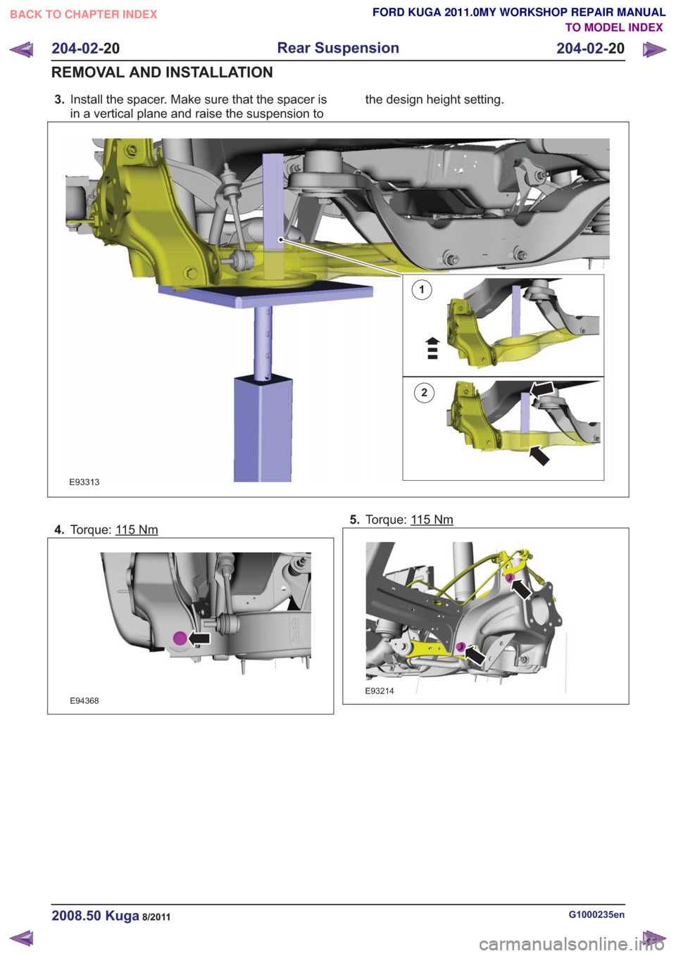
3.Install the spacer. Make sure that the spacer is
in a vertical plane and raise the suspension to the design height setting.
1
2
E93313
4.
Torque: 115Nm
E94368
5.Torque: 115Nm
E93214
G1000235en2008.50 Kuga8/2011
204-02- 20
Rear Suspension
204-02- 20
REMOVAL AND INSTALLATION
TO MODEL INDEX
BACK TO CHAPTER INDEX
FORD KUGA 2011.0MY WORKSHOP REPAIR MANUAL
Page 1223 of 2057

6.
E99208
7.Torque: 115Nm
E101643
8.Refer to: Wheel Bearing and Wheel Hub (204-02
Rear Suspension, Removal and Installation).
9. Refer to: Spring(204-02 Rear Suspension,
Removal and Installation).
G1000235en2008.50 Kuga8/2011
204-02- 21
Rear Suspension
204-02- 21
REMOVAL AND INSTALLATION
TO MODEL INDEX
BACK TO CHAPTER INDEX
FORD KUGA 2011.0MY WORKSHOP REPAIR MANUAL
Page 1224 of 2057
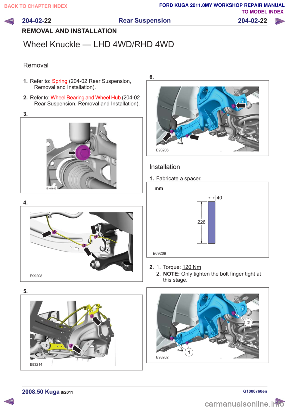
Wheel Knuckle — LHD 4WD/RHD 4WD
Removal
1.Refer to: Spring(204-02 Rear Suspension,
Removal and Installation).
2. Refer to: Wheel Bearing and Wheel Hub (204-02
Rear Suspension, Removal and Installation).
3.
E101643
4.
E99208
5.
E93214
6.
E93206
Installation
1. Fabricate a spacer.
E69209
226
40
2. Torque: 120Nm1.
2.NOTE: Only tighten the bolt finger tight at
this stage.
E932621
2
G1000760en2008.50 Kuga8/2011
204-02- 22
Rear Suspension
204-02- 22
REMOVAL AND INSTALLATION
TO MODEL INDEX
BACK TO CHAPTER INDEX
FORD KUGA 2011.0MY WORKSHOP REPAIR MANUAL
Page 1225 of 2057
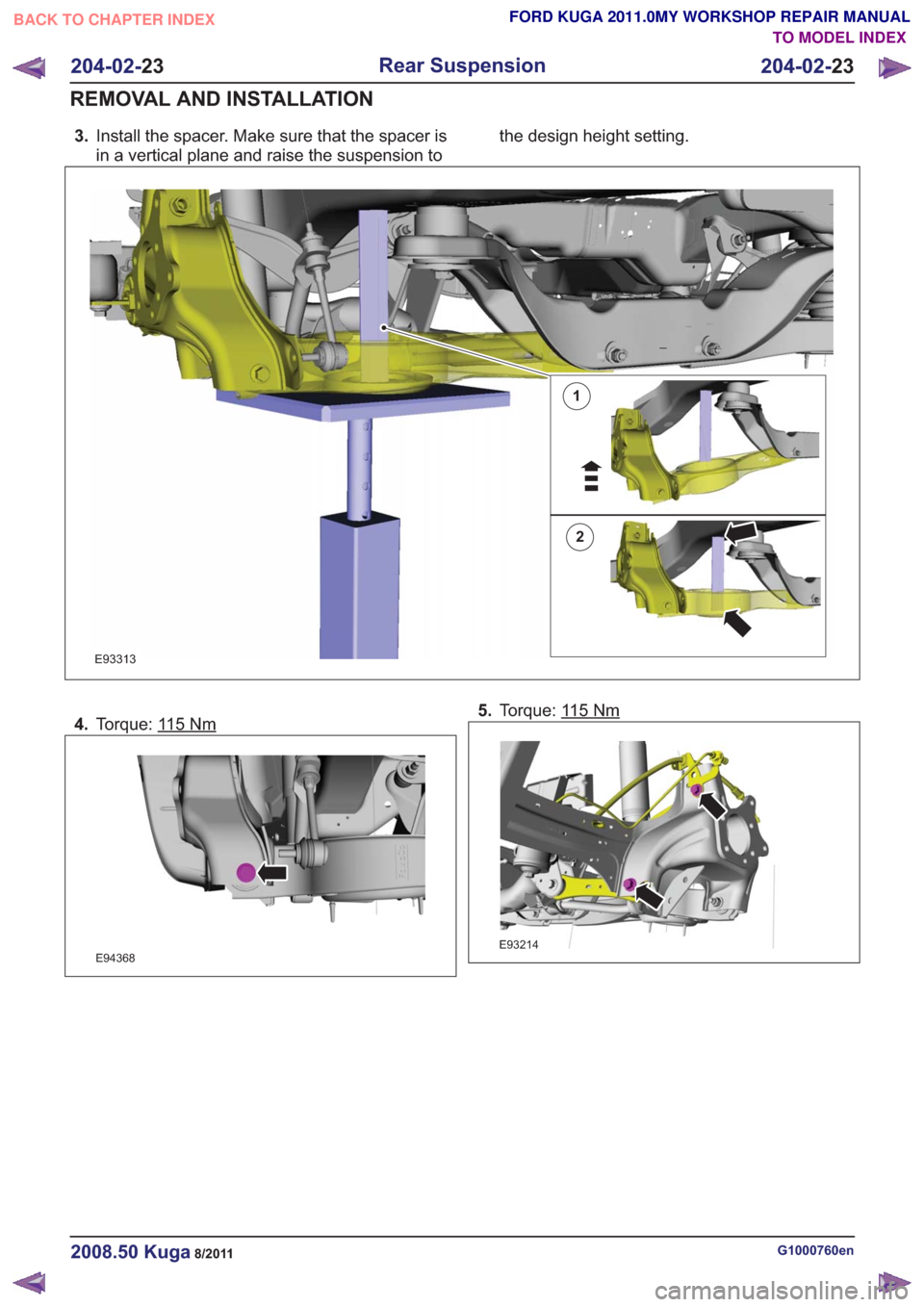
3.Install the spacer. Make sure that the spacer is
in a vertical plane and raise the suspension to the design height setting.
1
2
E93313
4.
Torque: 115Nm
E94368
5.Torque: 115Nm
E93214
G1000760en2008.50 Kuga8/2011
204-02- 23
Rear Suspension
204-02- 23
REMOVAL AND INSTALLATION
TO MODEL INDEX
BACK TO CHAPTER INDEX
FORD KUGA 2011.0MY WORKSHOP REPAIR MANUAL
Page 1226 of 2057
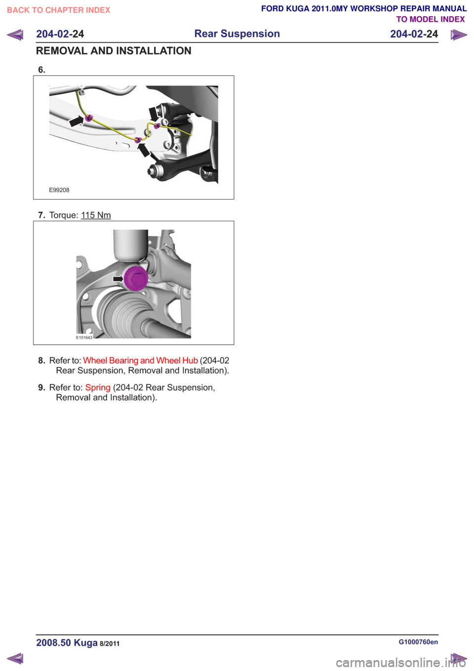
6.
E99208
7.Torque: 115Nm
E101643
8.Refer to: Wheel Bearing and Wheel Hub (204-02
Rear Suspension, Removal and Installation).
9. Refer to: Spring(204-02 Rear Suspension,
Removal and Installation).
G1000760en2008.50 Kuga8/2011
204-02- 24
Rear Suspension
204-02- 24
REMOVAL AND INSTALLATION
TO MODEL INDEX
BACK TO CHAPTER INDEX
FORD KUGA 2011.0MY WORKSHOP REPAIR MANUAL
Page 1227 of 2057
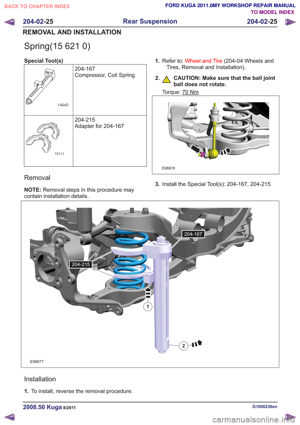
Spring(15 621 0)
Special Tool(s)204-167
Compressor, Coil Spring
14042
204-215
Adapter for 204-167
15111
Removal
NOTE:Removal steps in this procedure may
contain installation details. 1.
Refer to: Wheel and Tire (204-04 Wheels and
Tires, Removal and Installation).
2. CAUTION: Make sure that the ball joint ball does not rotate.
Torque: 70Nm
E98878
3.Install the Special Tool(s): 204-167, 204-215
E98877
1
2
204-167
204-215
Installation
1.To install, reverse the removal procedure.
G1000236en2008.50 Kuga8/2011
204-02- 25
Rear Suspension
204-02- 25
REMOVAL AND INSTALLATION
TO MODEL INDEX
BACK TO CHAPTER INDEX
FORD KUGA 2011.0MY WORKSHOP REPAIR MANUAL
Page 1233 of 2057
Wheels and Tires
Inspection and Verification
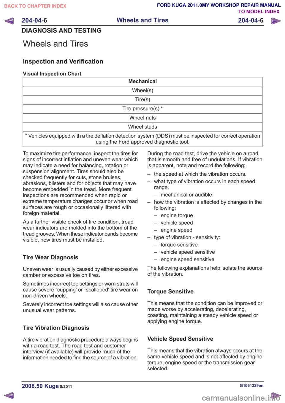
Visual Inspection Chart
MechanicalWheel(s)Tire(s)
Tire pressure(s) * Wheel nuts
Wheel studs
* Vehicles equipped with a tire deflation detection system (DDS) must be inspected for correct operation using the Ford approved diagnostic tool.
To maximize tire performance, inspect the tires for
signs of incorrect inflation and uneven wear which
may indicate a need for balancing, rotation or
suspension alignment. Tires should also be
checked frequently for cuts, stone bruises,
abrasions, blisters and for objects that may have
become embedded in the tread. More frequent
inspections are recommended when rapid or
extreme temperature changes occur or when road
surfaces are rough or occasionally littered with
foreign material.
As a further visible check of tire condition, tread
wear indicators are molded into the bottom of the
tread grooves. When these indicator bands become
visible, new tires must be installed.
Tire Wear Diagnosis
Uneven wear is usually caused by either excessive
camber or excessive toe on tires.
Sometimes incorrect toe settings or worn struts will
cause severe `cupping' or `scalloped' tire wear on
non-driven wheels.
Severely incorrect toe settings will also cause other
unusual wear patterns.
Tire Vibration Diagnosis
A tire vibration diagnostic procedure always begins
with a road test. The road test and customer
interview (if available) will provide much of the
information needed to find the source of a vibration. During the road test, drive the vehicle on a road
that is smooth and free of undulations. If vibration
is apparent, note and record the following:
– the speed at which the vibration occurs.
– what type of vibration occurs in each speed
range.
– mechanical or audible
– how the vibration is affected by changes in the following:
– engine torque
– vehicle speed
– engine speed
– type of vibration - sensitivity: – torque sensitive
– vehicle speed sensitive
– engine speed sensitive
The following explanations help isolate the source
of the vibration.
Torque Sensitive
This means that the condition can be improved or
made worse by accelerating, decelerating,
coasting, maintaining a steady vehicle speed or
applying engine torque.
Vehicle Speed Sensitive
This means that the vibration always occurs at the
same vehicle speed and is not affected by engine
torque, engine speed or the transmission gear
selected.
G1061329en2008.50 Kuga8/2011
204-04- 6
Wheels and Tires
204-04- 6
DIAGNOSIS AND TESTING
TO MODEL INDEX
BACK TO CHAPTER INDEX
FORD KUGA 2011.0MY WORKSHOP REPAIR MANUAL
Page 1238 of 2057
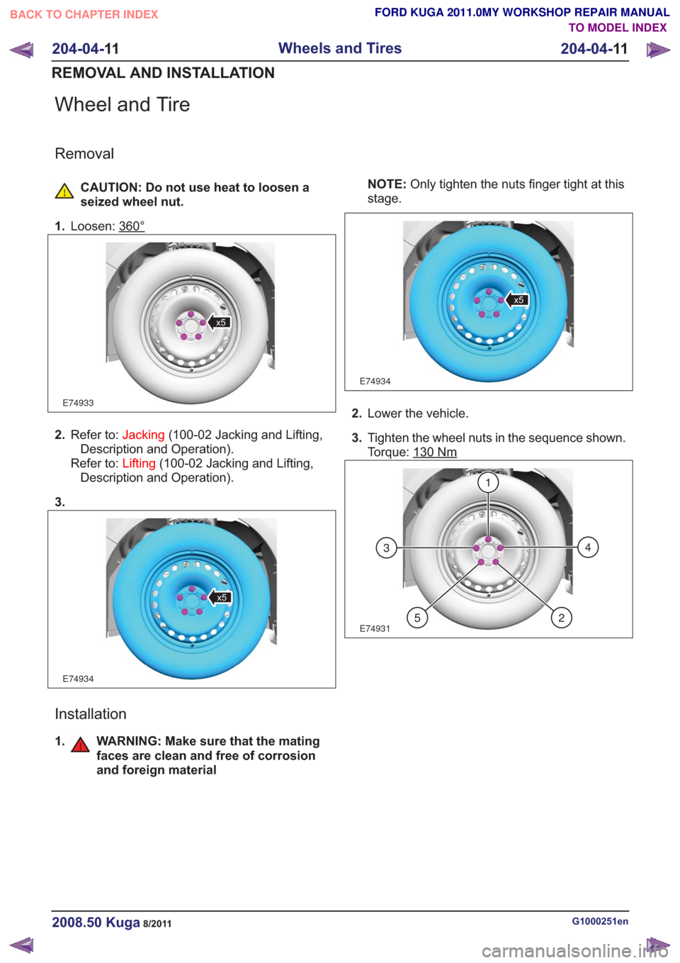
Wheel and Tire
Removal
CAUTION: Do not use heat to loosen a
seized wheel nut.
1. Loosen: 360°
E74933
x5
2.Refer to: Jacking(100-02 Jacking and Lifting,
Description and Operation).
Refer to: Lifting(100-02 Jacking and Lifting,
Description and Operation).
3.
E74934
x5
Installation
1. WARNING: Make sure that the mating faces are clean and free of corrosion
and foreign material
NOTE: Only tighten the nuts finger tight at this
stage.
E74934
x5
2. Lower the vehicle.
3. Tighten the wheel nuts in the sequence shown.
Torque: 130
Nm
E74931
1
43
25
G1000251en2008.50 Kuga8/2011
204-04- 11
Wheels and Tires
204-04- 11
REMOVAL AND INSTALLATION
TO MODEL INDEX
BACK TO CHAPTER INDEX
FORD KUGA 2011.0MY WORKSHOP REPAIR MANUAL
Page 1243 of 2057
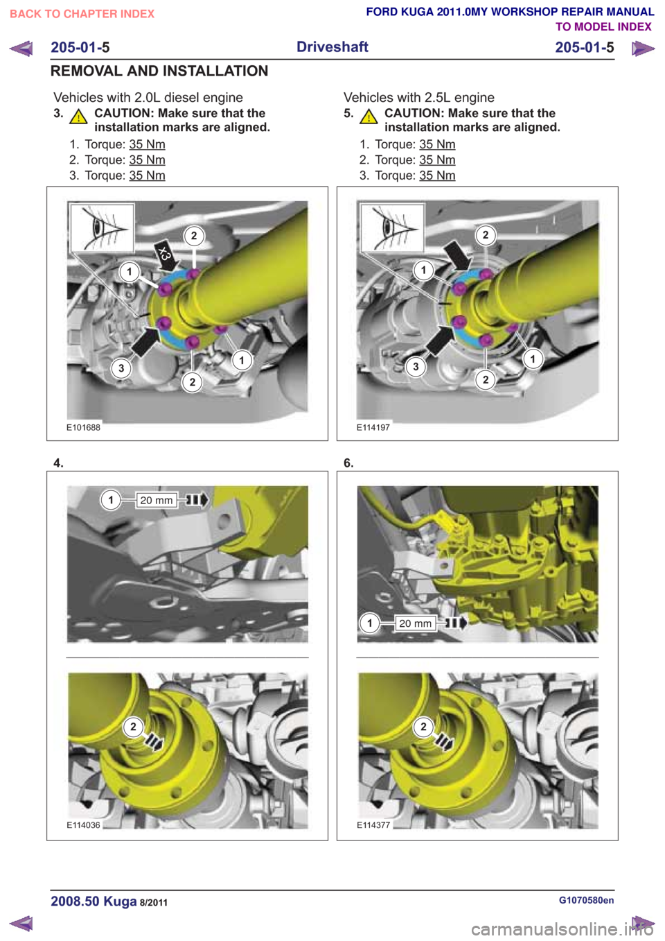
Vehicles with 2.0L diesel engine
3. CAUTION: Make sure that theinstallation marks are aligned.
1. Torque: 35Nm
2. Torque: 35Nm
3. Torque: 35Nm
3
1
2
2x3
13
1
2
2x3
1
E101688
4.
20 mm1
2
20 mm1
2
E114036
Vehicles with 2.5L engine
5. CAUTION: Make sure that theinstallation marks are aligned.
1. Torque: 35Nm
2. Torque: 35Nm
3. Torque: 35Nm
3
1
2
2
13
1
2
2
1
E114197
6.
20 mm1
2
20 mm1
2
E114377
G1070580en2008.50 Kuga8/2011
205-01- 5
Driveshaft
205-01- 5
REMOVAL AND INSTALLATION
TO MODEL INDEX
BACK TO CHAPTER INDEX
FORD KUGA 2011.0MY WORKSHOP REPAIR MANUAL
Page 1244 of 2057
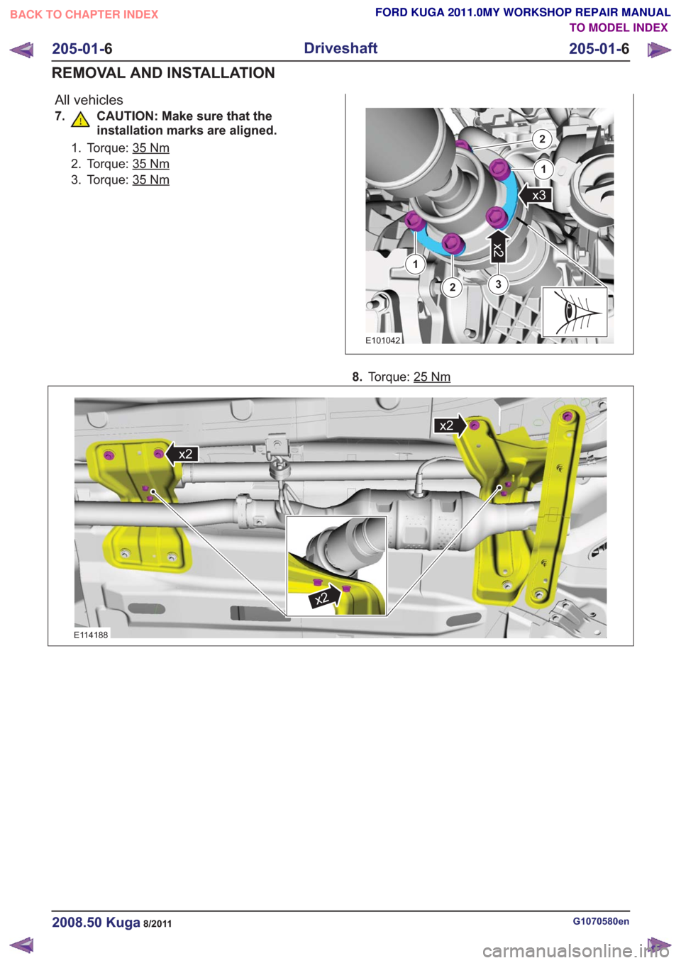
All vehicles
7. CAUTION: Make sure that theinstallation marks are aligned.
1. Torque: 35Nm
2. Torque: 35Nm
3. Torque: 35Nm
3
x2
2
1
2
1
x3
3
x2
2
1
2
1
x3
E101042
8.Torque: 25Nm
x2
x2
x2
x2
x2
x2
E114188
G1070580en2008.50 Kuga8/2011
205-01- 6
Driveshaft
205-01- 6
REMOVAL AND INSTALLATION
TO MODEL INDEX
BACK TO CHAPTER INDEX
FORD KUGA 2011.0MY WORKSHOP REPAIR MANUAL