rain sensor FORD KUGA 2011 1.G Workshop Manual
[x] Cancel search | Manufacturer: FORD, Model Year: 2011, Model line: KUGA, Model: FORD KUGA 2011 1.GPages: 2057
Page 160 of 2057

Description
Item
Electric Booster HeaterRefer to Component Description: (page
?)
1
GEM (generic electronic module)
2
Outside temperature sensor
3
Climate control system control assembly
4 Description
Item
Generator and Alternator
5
PCM (powertrain control module)
6
Coolant temperature sensor (ECT (engine
coolant temperature) sensor)Refer to Component Description: ECT
(page ?)
7
instrument cluster
8 G1066982en
2008.50 Kuga 8/2011 412-02-7
Auxiliary Climate Control
412-02-7
DESCRIPTION AND OPERATIONTO MODEL INDEX
BACK TO CHAPTER INDEX
FORD KUGA 2011.0MY WORKSHOP REPAIR MANUAL
Page 167 of 2057
reprogrammed. However, if the engine hasn't been
run since the last programmed start, the fuel-fired
booster heater will not start up the second time so
as to prevent the battery from being discharged.
The length of time required to pre-heat the vehicle
is calculated in the control unit of the fuel-fired
booster heater and is based on two temperature
values:
• Ambient air temperature: this message is taken
from the GEM via the CAN bus.
• Coolant temperature: this is determined via an internal sensor in the fuel-fired booster heater.
The maximum heating time is 30 minutes at an
outside air temperature of -10 °C or lower. The
heating time decreases proportionally with
increasing ambient temperature until the ambient
temperature is between +15 °C and +20 °C. Then
the minimum heating time is 10 minutes. The
parking heater is deactivated at temperatures
above +20 °C.
The sequence for a programmed start of the
booster heater is as follows:
• Two minutes before the start of the maximum heating time the driver information
system/instrument cluster sends an activation
message to the fuel-fired booster heater via the
CAN bus.
• The fuel-fired booster heater calculates the required heating time and, if necessary, sends
a delay request on the CAN bus.
• At the calculated time, the fuel-fired booster heater starts up. The conditions for start-up are:
engine not running and amount of fuel in the
fuel tank is above 14% of maximum.
• When the coolant temperature reaches +30 °C, the control unit of the fuel-fired booster heater
sends a request to switch on the passenger
compartment blower.
• Eight minutes after the programmed switch-off time, the booster heater stops heating mode
and starts a run-on operation to clean the
system's spark plugs.
• Ten minutes after the switch-off time, the post-cleaning operation is complete. The
additional ten minutes run-on time provides
some leeway in case the driver is late arriving.
After a programmed start-up of the booster heater
it is switched off again after the heating time has
elapsed (or if the fuel level in the fuel tank drops
below 8%). The booster heater stops within 2 minutes of the engine starting. This leaves enough
time to check whether the switch-on conditions for
boost heat mode have been met, thus preventing
the booster heater from having to switch off and
switch back on again. The heater can be switched
off manually at any time from the menu.
Whilst the fuel-fired booster heater is in additional
heating mode and/or parking heating mode, the
instrument cluster receives a fuel consumption
signal; this is used to re-calculate the vehicle's
remaining range and fuel consumption data.
Emergency shutoff
In the event of an accident in which the airbags
are deployed, the control unit of the fuel-fired
booster heater receives a message on the CAN
bus from the restraints control module (RCM).
When this message is received, the booster heater
system switches off immediately.
The booster heater control module deactivates the
system and does not respond to further messages
on the CAN bus. The booster heater control module
needs to be activated with WDS.
Component Description
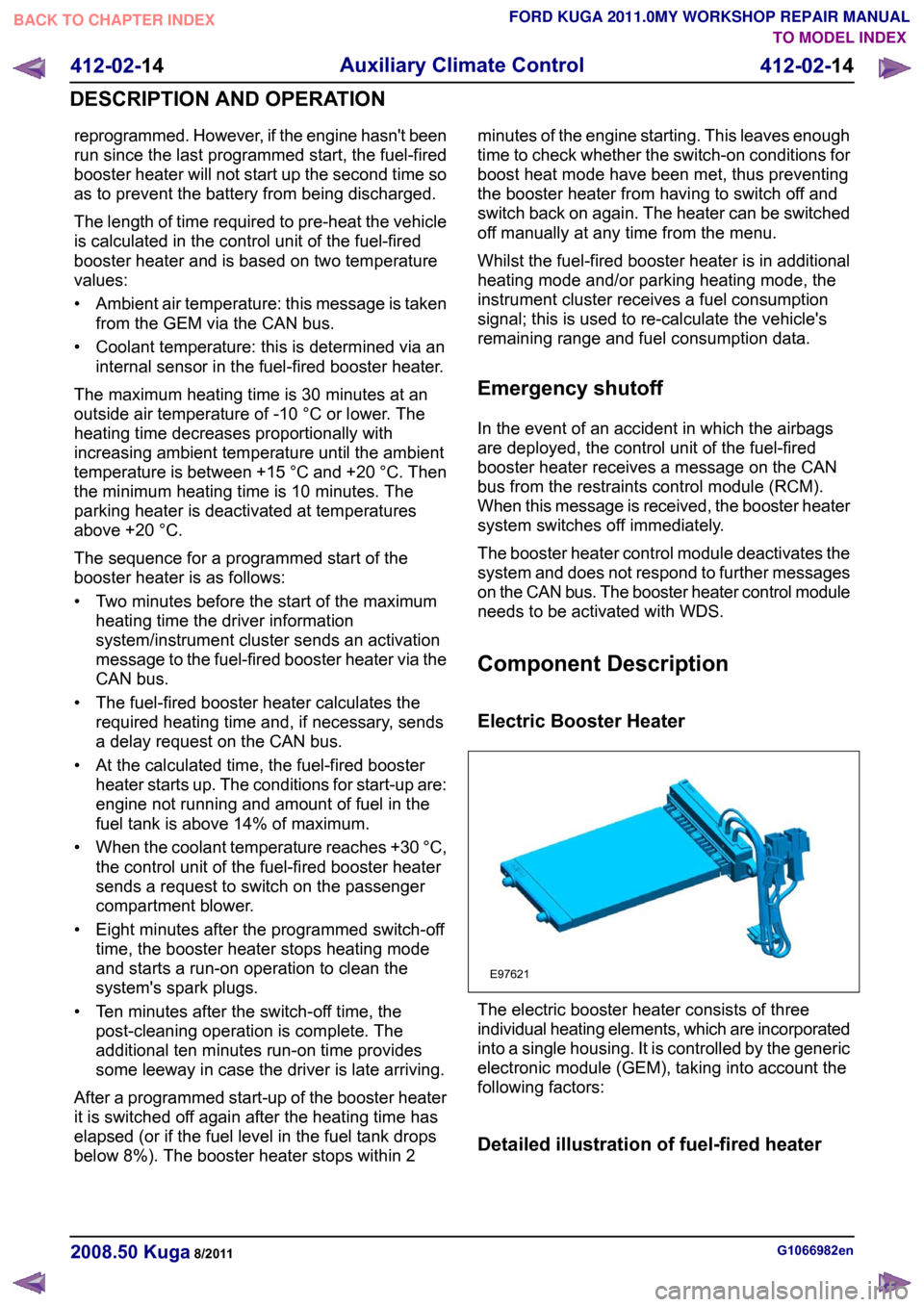
Electric Booster Heater
The electric booster heater consists of three
individual heating elements, which are incorporated
into a single housing. It is controlled by the generic
electronic module (GEM), taking into account the
following factors:
Detailed illustration of fuel-fired heater
G1066982en
2008.50 Kuga 8/2011 412-02-14
Auxiliary Climate Control
412-02-14
DESCRIPTION AND OPERATIONTO MODEL INDEX
BACK TO CHAPTER INDEX
FORD KUGA 2011.0MY WORKSHOP REPAIR MANUALE97621
Page 187 of 2057
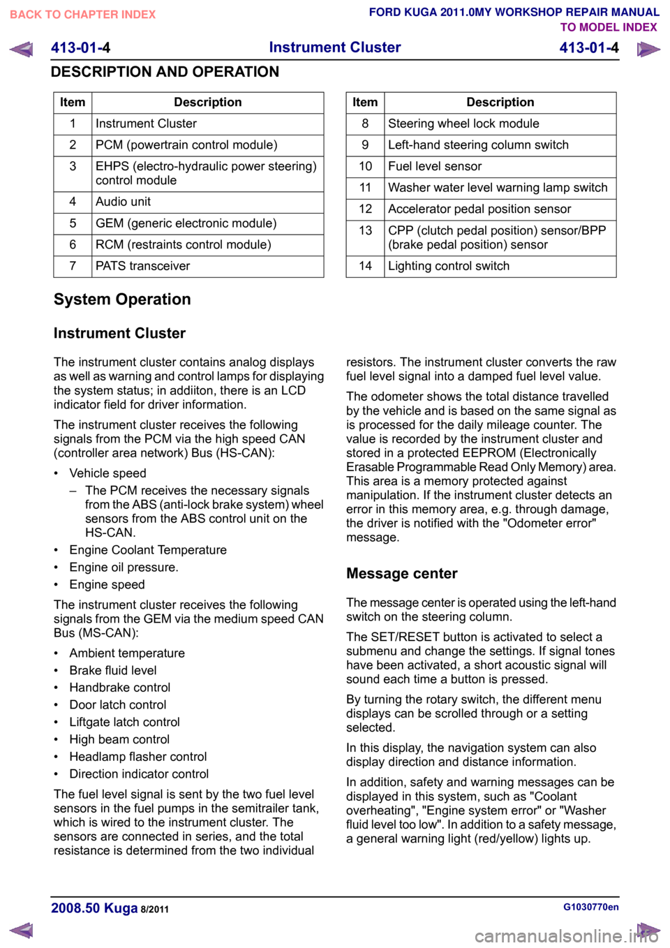
Description
Item
Instrument Cluster
1
PCM (powertrain control module)
2
EHPS (electro-hydraulic power steering)
control module
3
Audio unit
4
GEM (generic electronic module)
5
RCM (restraints control module)
6
PATS transceiver
7 Description
Item
Steering wheel lock module
8
Left-hand steering column switch
9
Fuel level sensor
10
Washer water level warning lamp switch
11
Accelerator pedal position sensor
12
CPP (clutch pedal position) sensor/BPP
(brake pedal position) sensor
13
Lighting control switch
14
System Operation
Instrument Cluster
The instrument cluster contains analog displays
as well as warning and control lamps for displaying
the system status; in addiiton, there is an LCD
indicator field for driver information.
The instrument cluster receives the following
signals from the PCM via the high speed CAN
(controller area network) Bus (HS-CAN):
• Vehicle speed – The PCM receives the necessary signalsfrom the ABS (anti-lock brake system) wheel
sensors from the ABS control unit on the
HS-CAN.
• Engine Coolant Temperature
• Engine oil pressure.
• Engine speed
The instrument cluster receives the following
signals from the GEM via the medium speed CAN
Bus (MS-CAN):
• Ambient temperature
• Brake fluid level
• Handbrake control
• Door latch control
• Liftgate latch control
• High beam control
• Headlamp flasher control
• Direction indicator control
The fuel level signal is sent by the two fuel level
sensors in the fuel pumps in the semitrailer tank,
which is wired to the instrument cluster. The
sensors are connected in series, and the total
resistance is determined from the two individual resistors. The instrument cluster converts the raw
fuel level signal into a damped fuel level value.
The odometer shows the total distance travelled
by the vehicle and is based on the same signal as
is processed for the daily mileage counter. The
value is recorded by the instrument cluster and
stored in a protected EEPROM (Electronically
Erasable Programmable Read Only Memory) area.
This area is a memory protected against
manipulation. If the instrument cluster detects an
error in this memory area, e.g. through damage,
the driver is notified with the "Odometer error"
message.
Message center
The message center is operated using the left-hand
switch on the steering column.
The SET/RESET button is activated to select a
submenu and change the settings. If signal tones
have been activated, a short acoustic signal will
sound each time a button is pressed.
By turning the rotary switch, the different menu
displays can be scrolled through or a setting
selected.
In this display, the navigation system can also
display direction and distance information.
In addition, safety and warning messages can be
displayed in this system, such as "Coolant
overheating", "Engine system error" or "Washer
fluid level too low". In addition to a safety message,
a general warning light (red/yellow) lights up.
G1030770en
2008.50 Kuga 8/2011 413-01-4
Instrument Cluster
413-01-4
DESCRIPTION AND OPERATIONTO MODEL INDEX
BACK TO CHAPTER INDEX
FORD KUGA 2011.0MY WORKSHOP REPAIR MANUAL
Page 335 of 2057
SECTION 417-01 Exterior Lighting
VEHICLE APPLICATION:
2008.50 Kuga
PAGE
CONTENTS
SPECIFICATIONS
417-01-3
Specifications ......................................................................................................................
417-01-3
Headlamp adjustment.....................................................................................................
DESCRIPTION AND OPERATION 417-01-4
Exterior Lighting (Component Location).............................................................................
417-01-5
Exterior Lighting (Overview)...............................................................................................
417-01-5
Front headlamps.................................................................................................................
417-01-5
Conventional Headlamps................................................................................................
417-01-5
Xenon headlamp.............................................................................................................
417-01-6
Headlamp levelling.........................................................................................................
417-01-7
Combined rain sensor/light sensor.....................................................................................
417-01-7
autolamps ...........................................................................................................................
417-01-7
Headlamp switch-off delay.................................................................................................
417-01-7
Turn signals........................................................................................................................
417-01-7
Door entry illumination........................................................................................................
417-01-8
Rear Lighting......................................................................................................................
417-01-9
Exterior Lighting (System Operation and Component Description)....................................
417-01-9
System Diagram.................................................................................................................
417-01-10
System Operation...............................................................................................................
417-01-10
Headlamp levelling.........................................................................................................
417-01-10
Xenon headlamp.............................................................................................................
417-01-10
Conventional Headlamps................................................................................................
417-01-11
Turn signals....................................................................................................................
417-01-11
Combined rain sensor/light sensor.................................................................................
417-01-11
Component Description......................................................................................................417-01-11Combined rain sensor/light sensor.................................................................................
DIAGNOSIS AND TESTING 417-01-12
Fog Lamps..........................................................................................................................
417-01-12
Description of operation......................................................................................................
417-01-13
Inspection and Checking....................................................................................................
417-01-15
Headlamps..........................................................................................................................
417-01-15
Description of operation......................................................................................................
417-01-16
Inspection and Checking....................................................................................................
417-01-17
Headlamp Leveling.............................................................................................................
417-01-17
Description of operation......................................................................................................
417-01-18
Inspection and Checking....................................................................................................
417-01-19
Parking, Rear and License Plate Lamps............................................................................
417-01-19
Description of operation......................................................................................................
417-01-20
Inspection and Checking....................................................................................................
417-01-21
Reversing Lamps................................................................................................................
417-01-21
Description of operation......................................................................................................
417-01-22
Inspection and Checking.................................................................................................... 417-01-1
Exterior Lighting
417-01-1
.
TO MODEL INDEX
BACK TO CHAPTER INDEX
PAGE 1 OF 2 FORD KUGA 2011.0MY WORKSHOP REPAIR MANUAL
Page 338 of 2057
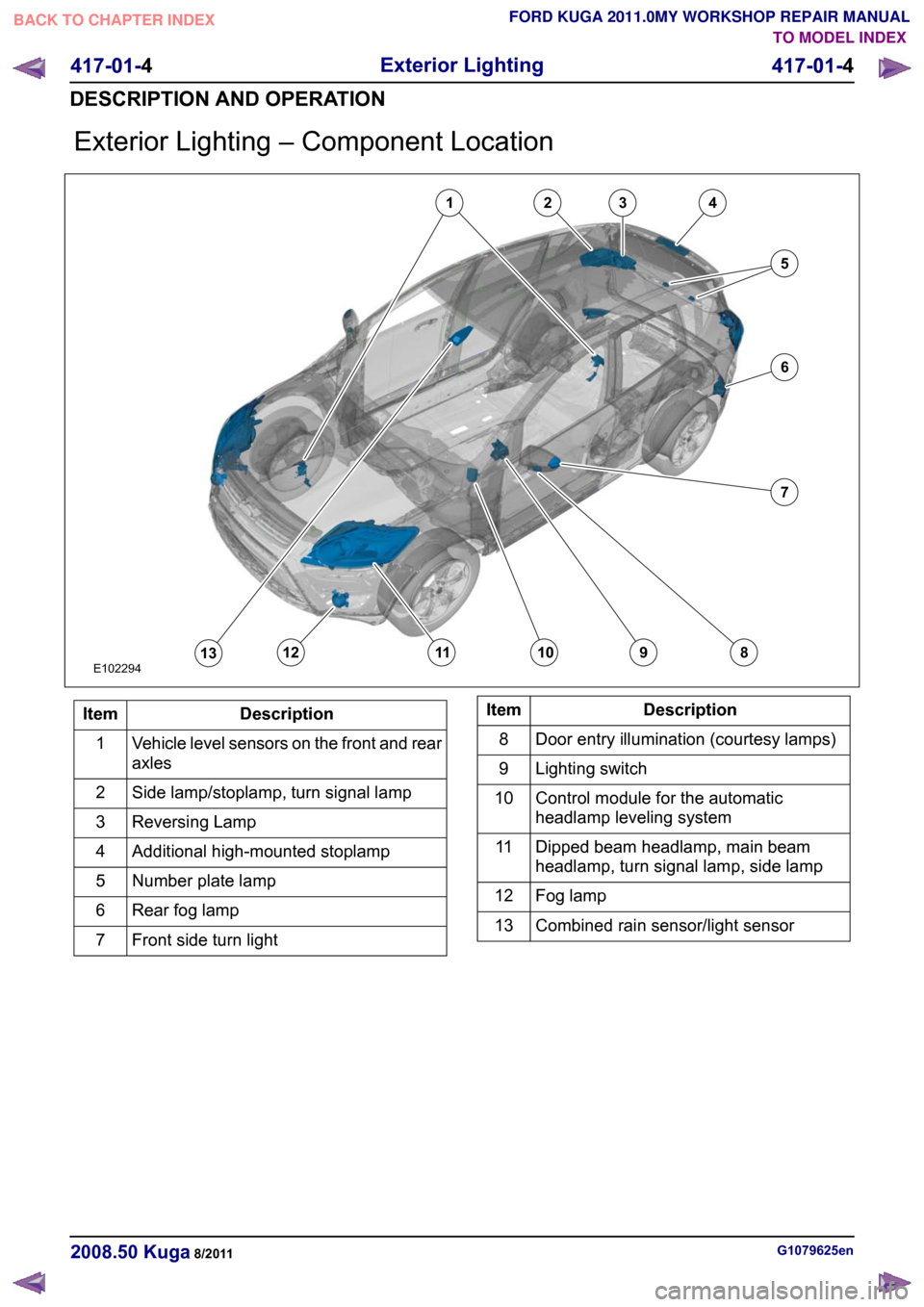
Exterior Lighting – Component Location
Description
Item
Vehicle level sensors on the front and rear
axles
1
Side lamp/stoplamp, turn signal lamp
2
Reversing Lamp
3
Additional high-mounted stoplamp
4
Number plate lamp
5
Rear fog lamp
6
Front side turn light
7 Description
Item
Door entry illumination (courtesy lamps)
8
Lighting switch
9
Control module for the automatic
headlamp leveling system
10
Dipped beam headlamp, main beam
headlamp, turn signal lamp, side lamp
11
Fog lamp
12
Combined rain sensor/light sensor
13 G1079625en
2008.50 Kuga 8/2011 417-01-4
Exterior Lighting
417-01-4
DESCRIPTION AND OPERATIONTO MODEL INDEX
BACK TO CHAPTER INDEX
FORD KUGA 2011.0MY WORKSHOP REPAIR MANUALE10229412345678910111213
Page 341 of 2057
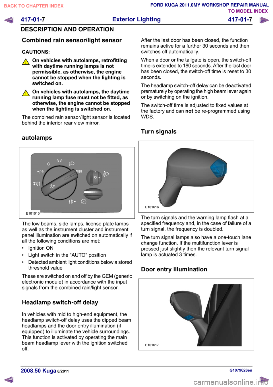
Combined rain sensor/light sensor
CAUTIONS:
On vehicles with autolamps, retrofitting
with daytime running lamps is not
permissible, as otherwise, the engine
cannot be stopped when the lighting is
switched on.
On vehicles with autolamps, the daytime
running lamp fuse must not be fitted, as
otherwise, the engine cannot be stopped
when the lighting is switched on.
The combined rain sensor/light sensor is located
behind the interior rear view mirror.
autolamps The low beams, side lamps, license plate lamps
as well as the instrument cluster and instrument
panel illumination are switched on automatically if
all the following conditions are met:
• Ignition ON
• Light switch in the "AUTO" position
•
Detected ambient light conditions below a stored
threshold value
These are switched on and off by the GEM (generic
electronic module) in accordance with the input
signals from the combined rain/light sensor.
Headlamp switch-off delay
In vehicles with mid to high-end equipment, the
headlamp switch-off delay uses the dipped beam
headlamps and the door entry illumination (if
equipped) to illuminate the vehicle surroundings.
This function is activated by operating the main
beam headlamp lever with the ignition switched
off. After the last door has been closed, the function
remains active for a further 30 seconds and then
switches off automatically.
When a door or the tailgate is open, the switch-off
time is extended to 180 seconds. After the last door
has been closed, the switch-off time is reset to 30
seconds.
The headlamp switch-off delay can be deactivated
prematurely by operating the high beam lever again
or by switching on the ignition.
The switch-off time is adjusted to fixed values at
the factory and can
notbe re-programmed using
WDS.
Turn signals The turn signals and the warning lamp flash at a
specified frequency and, in the case of failure of a
turn signal, the frequency is doubled.
The turn signal lamps also have a one-touch lane
change function. If the multifunction lever is
pressed just slightly then the relevant turn signal
lamp is actuated 3 times.
Door entry illumination
G1079626en
2008.50 Kuga 8/2011 417-01-7
Exterior Lighting
417-01-7
DESCRIPTION AND OPERATIONTO MODEL INDEX
BACK TO CHAPTER INDEX
FORD KUGA 2011.0MY WORKSHOP REPAIR MANUALE101615 E101616 E101617
Page 344 of 2057
Description
Item
Headlamp units with turn signal lamp, side
lamp, dipped beam headlamp, main beam
headlamp, positioning motor for headlamp
leveling system
8
External mirror with side turn signal lamps
and door entry lamp
9
Door locking units for the front doors
10
Fog lamp
11
Rear fog lights
12
Gas discharge headlamp control module
13 Description
Item
GEM14
Vehicle level sensors
15
Lighting switch
16
Multifunction lever
17
Hazard flasher switch
18
Combined rain sensor/light sensor
19
Reverse gear switch
20
Keyless Vehicle Module
21
System Operation
Headlamp levelling
Xenon headlamp
The following components are part of the automatic
headlamp leveling system:
• Vehicle level sensors on the front and rear axles
• Control module
• Actuator motors for headlamp leveling Accordingly, the system needs to be set up with
the aid of WDS after any components are replaced
or any other repairs are carried out.
The front and rear sensors are Hall sensors which
send a digital signal to the control unit.
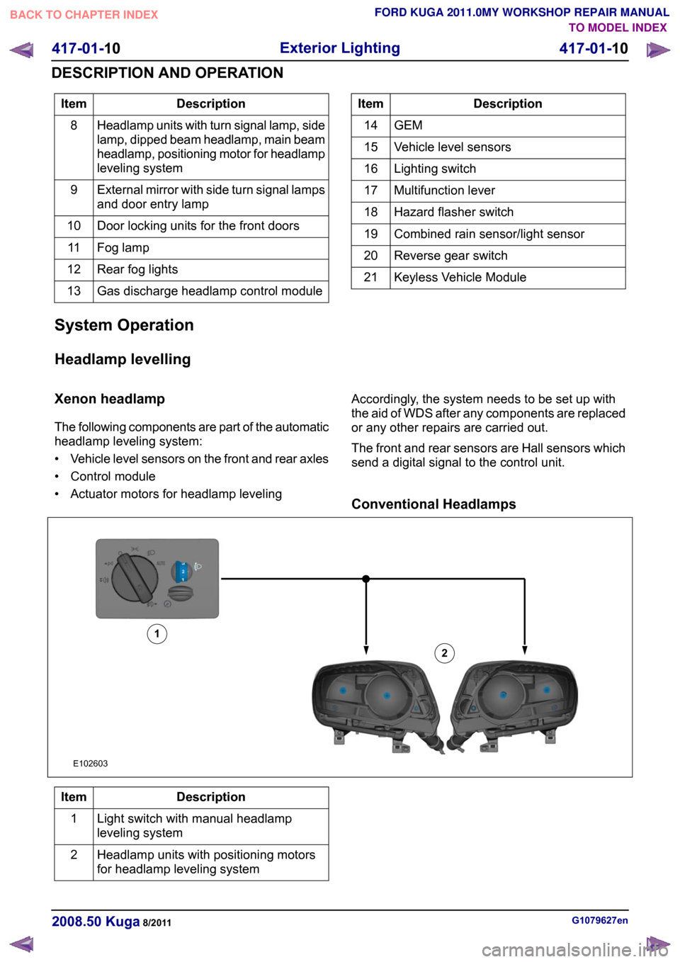
Conventional HeadlampsDescription
Item
Light switch with manual headlamp
leveling system
1
Headlamp units with positioning motors
for headlamp leveling system
2 G1079627en
2008.50 Kuga 8/2011 417-01-10
Exterior Lighting
417-01-10
DESCRIPTION AND OPERATIONTO MODEL INDEX
BACK TO CHAPTER INDEX
FORD KUGA 2011.0MY WORKSHOP REPAIR MANUALE10260312
Page 345 of 2057
The manual headlamp levelling system operates
with an electric motor which is controlled via a
rotary control in the instrument cluster.
Turn signals
The GEM switches the direction indicators and the
direction indicator side repeaters on.
The GEM sends a signal to the instrument cluster
via the CAN (controller area network) bus to switch
on the relevant turn indicator and the acoustic
signal.
The signals from the hazard flasher switch and
from the multifunction switch are transmitted to the
GEM via a wiring connection.
Combined rain sensor/light sensor
The ambient light sensor determines the general
light intensity.
For this purpose, it detects the light over as wide
an angle as possible, without taking the direction
of incidence into account.
The front light sensor determines the light intensity
directly in front of the vehicle.
If both the ambient light sensor and the front light
sensor detect a sudden reduction in light intensity
at the same time, then an algorithm-based
calculation is used to determine the fact that the
vehicle has entered a tunnel, a multi-storey car
park or a long underpass.
In this case the request for switching on the
external lighting and the indicator in the instrument
cluster is transmitted to the GEM.
If the vehicle enters into the shade thrown by a
large truck, the two sensors will register different
light intensities.. In this case, the algorithm-based
calculation will not result in the lights being
switched on.
The GEM incorporates a stepped switch-off of the
dipped beam headlamps, side lamps, license plate
illumination and the instrument cluster and
instrument panel illumination. If the ambient light
changes from dark to bright, the GEM first switches
off the low beams. The side lamps, license plate
lamps as well as the instrument cluster and
instrument panel illumination are switched off
approx. 6 seconds after the low beams have been
switched off.
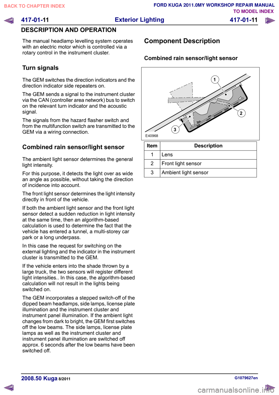
Component Description
Combined rain sensor/light sensor
Description
Item
Lens1
Front light sensor
2
Ambient light sensor
3 G1079627en
2008.50 Kuga 8/2011 417-01-11
Exterior Lighting
417-01-11
DESCRIPTION AND OPERATIONTO MODEL INDEX
BACK TO CHAPTER INDEX
FORD KUGA 2011.0MY WORKSHOP REPAIR MANUAL213E40968
Page 389 of 2057
Programmable Module Installation
Activation
5.
Install the most up-to-date software version in
IDS.
6. If, before replacing a module, it was not possible
to read out the vehicle-specific data using the
integrated diagnostic system (IDS) (the module
to be replaced does not respond) then, during
programming of the new module, the
vehicle-specific data must be entered manually
via a selection list in IDS or via a code which
can be obtained from the Technical Hotline.
7. In order to program, select the "Install
programmable module" submenu in the "Module
programming" menu tool box and then follow
the instructions.
8. The following modules must be programmed
after replacement:
•
• Anti-lock braking system module (ABS)
• Audio system module (ACM)
• CD player (CDP)
• Driver's door control unit (D-DCU)
• Passenger's door control unit (P-DCU)
• Rear left door control unit (RL-DCU)
• Rear right door control unit (RR-DCU)
• Electrical power steering (EPS)
• Generic Display Module (GDM) (vehicles
with DVD navigation system with
touchscreen)
• Generic electronic module (GEM)
• Headlamp control module (HCM) (vehicles with gas discharge headlamps)
• Instrument cluster (IC)
• Navigation system (NAV) (vehicles with navigation system)
• Parking aid module(PAM)
• Powertrain control module (PCM)
• Restraint control module (RCM)
• Rear entertainment system module (RETM) (vehicles with rear seat entertainment
system)
9. In order to configure the PCM, select the
"Programmable parameters" submenu in the
"Module programming" menu tool box and then
follow the instructions.
10. For vehicles with anti-lock braking system and
electronic stability program, these must also be configured using IDS following replacement of
the lateral acceleration sensor, yaw rate sensor
or pressure sensor. Configuration is performed
in the "Programmable parameters" menu tool
box.
G1158258en
2008.50 Kuga 8/2011 418-01-3
Module Configuration
418-01-3
GENERAL PROCEDURESTO MODEL INDEX
BACK TO CHAPTER INDEX
FORD KUGA 2011.0MY WORKSHOP REPAIR MANUAL
Page 451 of 2057
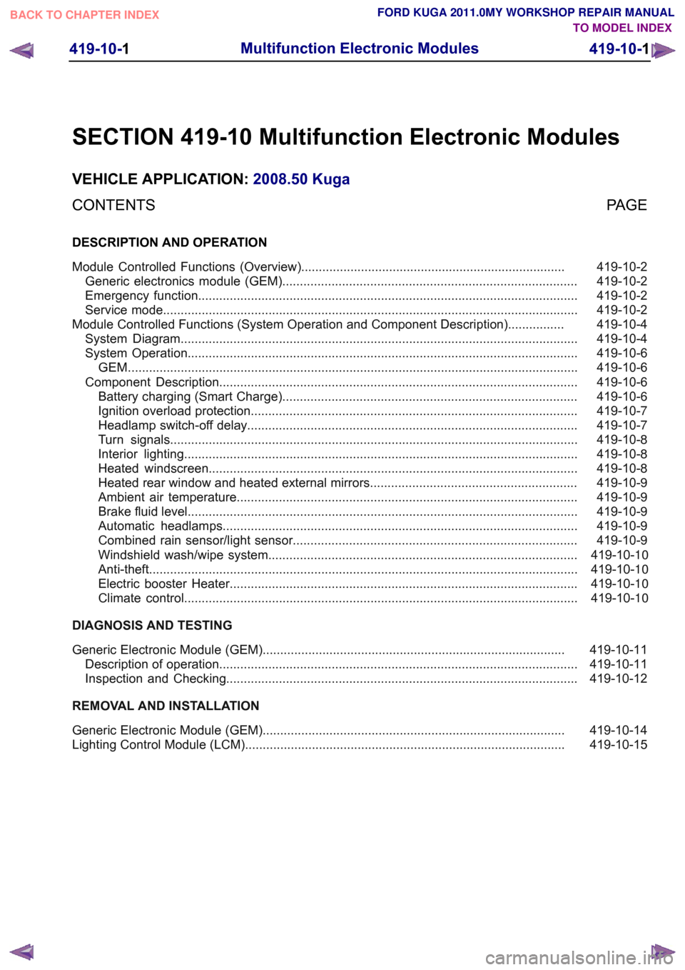
SECTION 419-10 Multifunction Electronic Modules
VEHICLE APPLICATION:
2008.50 Kuga
PAGE
CONTENTS
DESCRIPTION AND OPERATION
419-10-2
Module Controlled Functions (Overview)...........................................................................
419-10-2
Generic electronics module (GEM)....................................................................................
419-10-2
Emergency function............................................................................................................
419-10-2
Service mode......................................................................................................................
419-10-4
Module Controlled Functions (System Operation and Component Description)................
419-10-4
System Diagram.................................................................................................................
419-10-6
System Operation...............................................................................................................
419-10-6
GEM. ...............................................................................................................................
419-10-6
Component Description......................................................................................................
419-10-6
Battery charging (Smart Charge)....................................................................................
419-10-7
Ignition overload protection.............................................................................................
419-10-7
Headlamp switch-off delay..............................................................................................
419-10-8
Turn signals....................................................................................................................
419-10-8
Interior lighting................................................................................................................
419-10-8
Heated windscreen.........................................................................................................
419-10-9
Heated rear window and heated external mirrors...........................................................
419-10-9
Ambient air temperature.................................................................................................
419-10-9
Brake fluid level...............................................................................................................
419-10-9
Automatic headlamps.....................................................................................................
419-10-9
Combined rain sensor/light sensor.................................................................................419-10-10Windshield wash/wipe system........................................................................................
419-10-10Anti-theft ..........................................................................................................................
419-10-10Electric booster Heater...................................................................................................
419-10-10Climate control................................................................................................................
DIAGNOSIS AND TESTING 419-10-11
Generic Electronic Module (GEM)......................................................................................
419-10-11
Description of operation......................................................................................................
419-10-12
Inspection and Checking....................................................................................................
REMOVAL AND INSTALLATION 419-10-14
Generic Electronic Module (GEM)......................................................................................
419-10-15
Lighting Control Module (LCM)........................................................................................... 419-10-1
Multifunction Electronic Modules
419-10-1
.
TO MODEL INDEX
BACK TO CHAPTER INDEX
FORD KUGA 2011.0MY WORKSHOP REPAIR MANUAL