automatic FORD MUSTANG 1969 Volume One Chassis
[x] Cancel search | Manufacturer: FORD, Model Year: 1969, Model line: MUSTANG, Model: FORD MUSTANG 1969Pages: 413, PDF Size: 75.81 MB
Page 399 of 413

07-04-30
C-6 Automatic Transmission
07-04-30
6. Install the compressing tool
shown in Fig. 29 and compress the
springs just enough to install the low-
reverse clutch piston retainer snap
ring.
7.
Install the snap ring, then re-
move the compressing tool.
8. Place the transmission case on
the bench with the front end facing
downward.
9. Position the parking gear thrust
washer and the gear on the case (Fig.
33).
Do not restake the thrust washer.
10.
Position the oil distributor and
tubes in place on the rear of the case.
Install and torque the attaching bolts
to specification.
11.
Install the output shaft, and
governor as an assembly.
12.
Place a new gasket on the rear
of the transmission case. Position the
extension housing on the case and in-
stall the attaching bolts. Torque the
attaching bolts to specification.
13.
Place the case in the holding
fixture.
14.
Align the low-reverse clutch hub
and one-way clutch with the inner
race at the rear of the case. Rotate
the low-reverse clutch hub clockwise
while applying pressure to seat it on
the inner race.
15.
Install the low-reverse clutch
plates,
starting with a steel plate and
following with friction and steel plates
alternately. Retain them with vaseline.
Refer to the Specifications Section for
the number of plates required. If new
composition plates are being used,
soak them in clean transmission fluid
for fifteen minutes before installation.
Install the pressure plate and the snap
ring. Test the operation of the low-
reverse clutch by applying air pressure
at the clutch pressure apply hole in
the case.
16.
Install the reverse planet ring
gear thrust washer and the ring gear
and hub assembly. Insert the snap
ring in the groove in the output shaft.
17.
Assemble the front and rear
thrust washers onto the reverse planet
assembly; retain with vasoline. Insert
the assembly into the ring gear and
install the snap ring.
18.
Set the reverse-high clutch on
the bench, with the front end facing
down. Install the thrust washer on the
rear end of the reverse-high clutch as-
sembly. Retain the thrust washer with
vaseline and insert the splined end of
forward clutch into the open end of
the reverse-high clutch so that the
splines engage the direct clutch fric-
tion plates (Fig. 43).
19.
Install the thrust washer and re-
tain it with vaseline, on the front end
FORWARD
SNAP
RING
377300-S
SUN
GEAR
7A348
•
INPUT
SHELL
7D064
\
THRUST
WASHER
7D066
-IT
REAR
SNAP
RING
377300-S
I)
1634-A
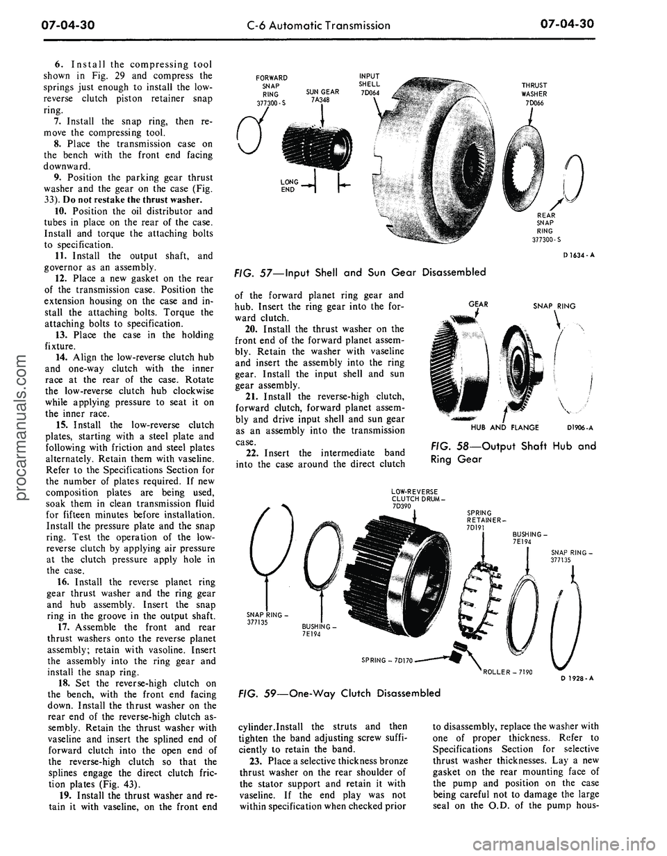
57—Input Shell and Sun Gear Disassembled
of the forward planet ring gear and
hub.
Insert the ring gear into the for-
ward clutch.
20.
Install the thrust washer on the
front end of the forward planet assem-
bly. Retain the washer with vaseline
and insert the assembly into the ring
gear. Install the input shell and sun
gear assembly.
21.
Install the reverse-high clutch,
forward clutch, forward planet assem-
bly and drive input shell and sun gear
as an assembly into the transmission
case.
22.
Insert the intermediate band
into the case around the direct clutch
GEAR
SNAP RING
HUB AND FLANGE
D1906-A
FIG. 58—Output Shaft Hub and
Ring Gear
LOW-REVERSE
CLUTCH
DRUM-
7D390
SPRING
RETAINER-
7D191
BUSHING
-
7E194
SPRING
-
7D170
ROLLER-7190
D 1928-A
FIG. 59—One-Way Clutch Disassembled
cylinder.Install the struts and then
tighten the band adjusting screw suffi-
ciently to retain the band.
23.
Place a selective thickness bronze
thrust washer on the rear shoulder of
the stator support and retain it with
vaseline. If the end play was not
within specification when checked prior
to disassembly, replace the washer with
one of proper thickness. Refer to
Specifications Section for selective
thrust washer thicknesses. Lay a new
gasket on the rear mounting face of
the pump and position on the case
being careful not to damage the large
seal on the O.D. of the pump hous-procarmanuals.com
Page 400 of 413

07-04-31
C-6 Automatic Transmission
07-04-31
ing. Install six of the seven mounting
bolts and torque them to specifica-
tion.
24.
Adjust the intermediate band as
detailed in Section 2 and install the
input shaft with the long splined end
inserted into the forward clutch as-
sembly.
LOW-REVERSE
SPRING LOAD ON ROLLERS CLUTCH HUB
MUST BE IN A COUNTERCLOCKWISE
DIRECTION FOR INSTALLATION Q 192O A
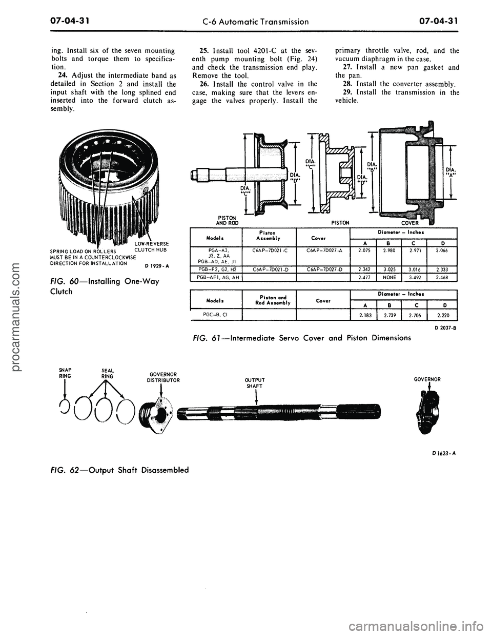
FIG. 60—Installing One-Way
Clutch
25.
Install tool 4201-C at the sev-
enth pump mounting bolt (Fig. 24)
and check the transmission end play.
Remove the tool.
26.
Install the control valve in the
case,
making sure that the levers en-
gage the valves properly. Install the
primary throttle valve, rod, and the
vacuum diaphragm in the case.
27.
Install a new pan gasket and
the pan.
28.
Install the converter assembly.
29.
Install the transmission in the
vehicle.
PISTON
AND ROD
PISTON
COVER
Models
PGA-A3,
J3,
Z, AA
PGB-AD,
AE, Jl
PGB-F2/G2, H2
PGB-AF1,
AG, AH
Piston
Assembly
C6AP-7D021-C
C6AP-7D021-D
Cover
C6AP-7D027-A
C6AP-7D027-D
Diameter - Inches
A
2.075
2.342
2.477
' B
2.980
3.025
NONE
c
2.971
3.016
3.492
D
2.066
2.333
2.468
Models
PGC-B,
Cl
Piston and
Rod Assembly
Cover
Diameter
—
Inches
A
2.183
B
2.739
C
2.705
D
2.220
D 2037-B
FIG.
61
— Intermediate Servo Cover and Piston Dimensions
OUTPUT
SHAFT
GOVERNOR
D
1623
-A
FIG. 62—Output Shaft Disassembledprocarmanuals.com