boot FORD MUSTANG 1969 Volume One Chassis
[x] Cancel search | Manufacturer: FORD, Model Year: 1969, Model line: MUSTANG, Model: FORD MUSTANG 1969Pages: 413, PDF Size: 75.81 MB
Page 22 of 413
02-02-03
Brake System
02-02-03
DESCRIPTION
Disc brakes are available as option-
al equipment for the front wheels on
Ford, Mercury, Meteor, Fairlane,
Montego, Falcon, Mustang and Cou-
gar models and are standard on Thun-
derbird, Continental Mark III, and
Lincoln Continental models. The
dual-master cylinder equipped hydrau-
lic brake system employs single an-
chor, internal expanding and
self-
adjusting drum brake assemblies on
the rear wheels of vehicles with disc
brakes, and on the front and rear
wheels of all others.
A vacuum booster is used with the
power disc brake system.
DUAL MASTER CYLINDER
BRAKE SYSTEM
The dual-master cylinder brake sys-
tem has been incorporated in all mod-
els to provide increased safety. The
system consists of a dual-master cylin-
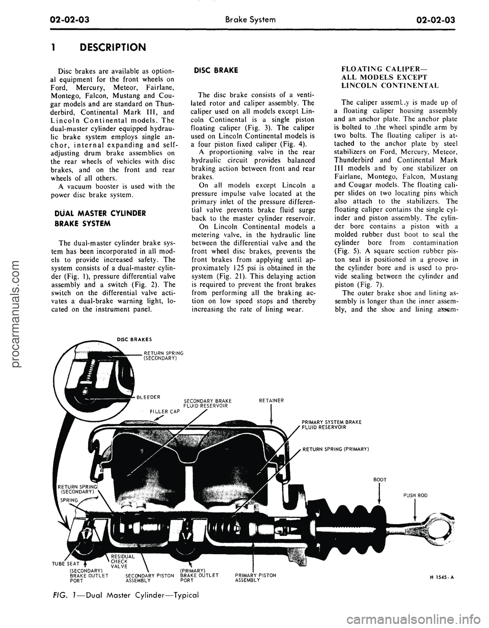
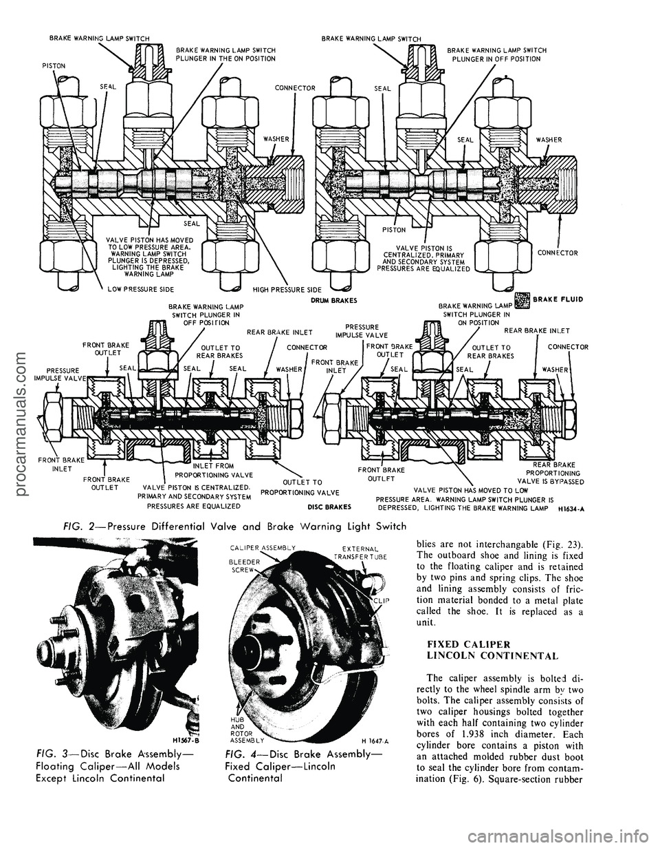
der (Fig. 1), pressure differential valve
assembly and a switch (Fig. 2). The
switch on the differential valve acti-
vates a dual-brake warning light, lo-
cated on the instrument panel.
DISC BRAKE
The disc brake consists of a venti-
lated rotor and caliper assembly. The
caliper used on all models except Lin-
coln Continental is a single piston
floating caliper (Fig. 3). The caliper
used on Lincoln Continental models is
a four piston fixed caliper (Fig. 4).
A proportioning valve in the rear
hydraulic circuit provides balanced
braking action between front and rear
brakes.
On all models except Lincoln a
pressure impulse valve located at the
primary inlet of the pressure differen-
tial valve prevents brake fluid surge
back to the master cylinder reservoir.
On Lincoln Continental models a
metering valve, in the hydraulic line
between the differential valve and the
front wheel disc brakes, prevents the
front brakes from applying until ap-
proximately 125 psi is obtained in the
system (Fig. 21). This delaying action
is required to prevent the front brakes
from performing all the braking ac-
tion on low speed stops and thereby
increasing the rate of lining wear.
FLOATING CALIPER—
ALL MODELS EXCEPT
LINCOLN CONTINENTAL
The caliper asseml.y is made up of
a floating caliper housing assembly
and an anchor plate. The anchor plate
is bolted to .the wheel spindle arm by
two bolts. The floating caliper is at-
tached to the anchor plate by steel
stabilizers on Ford, Mercury, Meteor,
Thunderbird and Continental Mark
III models and by one stabilizer on
Fairlane, Montego, Falcon, Mustang
and Cougar models. The floating cali-
per slides on two locating pins which
also attach to the stabilizers. The
floating caliper contains the single cyl-
inder and piston assembly. The cylin-
der bore contains a piston with a
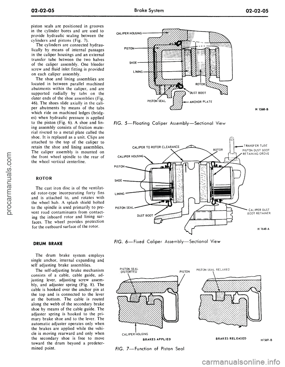
molded rubber dust boot to seal the
cylinder bore from contamination
(Fig. 5). A square section rubber pis-
ton seal is positioned in a groove in
the cylinder bore and is used to pro-
vide sealing between the cylinder and
piston (Fig. 7).
The outer brake shoe and lining as-
sembly is longer than the inner assem-
bly, and the shoe and lining
DISC BRAKES
RETURN SPRING
(SECONDARY)
RETAINER
PRIMARY SYSTEM BRAKE
FLUID RESERVOIR
BOOT
PUSH ROD
TUBE SEAT |
(SECONDARY)
BRAKE OUTLET
PORT
RESIDUAL \ ^
CHECK \
VALVE \
SECONDARY PISTON
ASSEMBLY
(PRIMARY)
BRAKE OUTLET
PORT
PRIMARY PISTON
ASSEMBLY
H 1545-A
FIG.
I
—
Dual
Master Cylinder—Typicalprocarmanuals.com
Page 23 of 413
BRAKE WARNING LAMP SWITCH
PISTON
BRAKE WARNING LAMP SWITCH
BRAKE WARNING LAMP SWITCH
PLUNGER IN THE ON POSITION
CONNECTOR
BRAKE WARNING LAMP SWITCH
PLUNGER IN OFF POSITION
VALVE PISTON HAS MOVED
TO LOW PRESSURE AREA.
WARNING LAMP SWITCH
PLUNGER IS DEPRESSED,
LIGHTING THE BRAKE
WARNING LAMP
LOW PRESSURE SIDE
U
VALVE PISTON IS
CENTRALIZED. PRIMARY
AND SECONDARY SYSTEM
PRESSURES ARE EQUALIZED
BRAKE WARNING LAMP
SWITCH PLUNGER IN
OFF POSITION
HIGH PRESSURE SIDE
DRUM BRAKES
TJ
CONNEiCTOR
BRAKE FLUID
BRAKE WARNING LAMP I
SWITCH PLUNGER IN
ON POSITION
REAR BRAKE INLET
CONNECTOR
FRONT BRAKE
INLET
FRONT BRAKE
OUTLET
VALVE PISTON IS CENTRALIZED.
PRIMARY AND SECONDARY SYSTEM
PRESSURES ARE EQUALIZED
OUTLET TO
PROPORTIONING VALVE
DISC BRAKES
\
REAR BRAKE
PROPORTIONING
VALVE IS BYPASSED
VALVE PISTON HAS MOVED TO LOW
PRESSURE AREA. WARNING LAMP SWITCH PLUNGER IS
DEPRESSED, LIGHTING THE BRAKE WARNING LAMP H1634-A
FIG. 2—Pressure Differential Valve and Brake Warning Light Switch
CALIPER ASSEMBLY
BLEEDER
SCREW
EXTERNAL
TRANSFERTU3E
H1567-B
HUB
AND
ROTOR
ASSEMBLY
H 1647-A
FIG. 3—Disc Brake Assembly-
Floating Caliper—All Models
Except Lincoln Continental
FIG. 4—Disc Brake Assembly—
Fixed Caliper—Lincoln
Continental
blies are not interchangable (Fig. 23).
The outboard shoe and lining is fixed
to the floating caliper and is retained
by two pins and spring clips. The shoe
and lining assembly consists of fric-
tion material bonded to a metal plate
called the shoe. It is replaced as a
unit.
FIXED CALIPER
LINCOLN CONTINENTAL
The caliper assembly is bolted di-
rectly to the wheel spindle arm by two
bolts.
The caliper assembly consists of
two caliper housings bolted together
with each half containing two cylinder
bores of 1.938 inch diameter. Each
cylinder bore contains a piston with
an attached molded rubber dust boot
to seal the cylinder bore from contam-
ination (Fig. 6). Square-section rubberprocarmanuals.com
Page 24 of 413
02-02-05
Brake System
02-02-05
piston seals are positioned in grooves
in the cylinder bores and are used to
provide hydraulic sealing between the
cylinders and pistons (Fig. 7).
The cylinders are connected hydrau-
lically by means of internal passages
in the caliper housings and an external
transfer tube between the two halves
of the caliper assembly. One bleeder
screw and fluid inlet fitting is provided
on each caliper assembly.
The shoe and lining assemblies are
located in between parallel machined
abutments within the caliper, and are
supported radially by tabs on the
o'uter ends of the shoe assemblies (Fig.
46).
The shoes slide axially in the cali-
per abutments by means of the tabs
which ride on machined ledges (bridg-
es) when hydraulic pressure is applied
to the piston (Fig. 6). A shoe and lin-
ing assembly consists of friction mate-
rial riveted to a metal plate called the
shoe.
It is replaced as a unit. Clips are
attached to the top of the caliper to
retain the shoe and lining assemblies.
The caliper assembly is mounted on
the front wheel spindle to the rear of
the wheel vertical centerline.
ROTOR
The cast iron disc is of the ventilat-
ed rotor-type incorporating forty fins
and is attached to, and rotates with
the wheel hub. A splash shield bolted
to the spindle is used primarily to pre-
vent road contaminants from contact-
ing the inboard rotor and lining sur-
faces.
The wheel provides protection
for the outboard surface of the rotor.
DRUM BRAKE
The drum brake system employs
single anchor, internal expanding ancj
self adjusting brake assemblies.
The self-adjusting brake mechanism
consists of a cable, cable guide, ad-
justing lever, adjusting screw assem-
bly, and adjuster spring (Fig. 8). The
cable is hooked over the anchor pin at
the top and is connected to the lever
at the bottom. The cable is routed
along the webb of the secondary brake
shoe by means of the cable guide. The
adjuster spring is hooked to the pri-
mary brake shoe and to the lever. The
automatic adjuster operates only when
the brakes are applied while the vehi-
cle is moving rearward and only when
the secondary shoe is free to move
toward the drum beyond a predeter-
mined point.
CALIPER
HOUSING
PISTON
SHOE
LINING
PISTON SEAL
FIG. 5—Floating Caliper Assembly—Sectional View
CALIPER
TO
ROTOR
CLEARANCE
CALIPER
HOUSING
PISTON
SHOE
LINING
PISTON SEAL
H 1568-B
TRANSFER
TUBE
PISTON DUST BOOT
RETAINING
GROVE
CALIPER
DUST
BOOT
RETAINER
H 1648-A
FIG.
6—Fixed
Caliper Assembly—Sectional View
PISTON
PISTON SEAL
RELAXED
CALIPER
HOUSING
BRAKES APPLIED
FIG. 7—Function of Piston Seal
BRAKES RELEASED
H1569-Bprocarmanuals.com
Page 26 of 413
02-02-07
Brake System
02-02-07
ANTI-SKID CONTROL SYSTEM
RELEASE PAWL CAM PIN
RELEASE PAWL CAM LEVER
RELEASE CABLE
H
1636-
A
FIG. 10—Parking Brake Control Assembly
With Manual Release—Typical
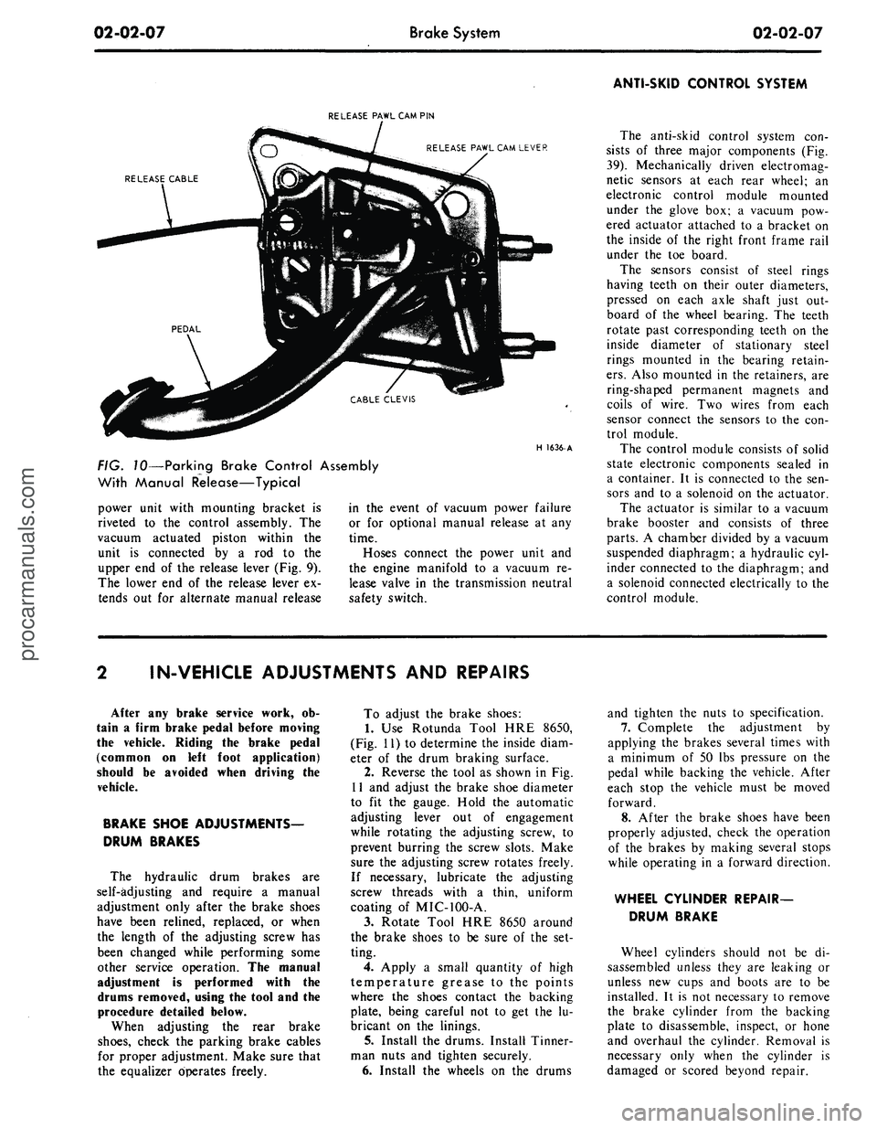
power unit with mounting bracket is
riveted to the control assembly. The
vacuum actuated piston within the
unit is connected by a rod to the
upper end of the release lever (Fig. 9).
The lower end of the release lever ex-
tends out for alternate manual release
in the event of vacuum power failure
or for optional manual release at any
time.
Hoses connect the power unit and
the engine manifold to a vacuum re-
lease valve in the transmission neutral
safety switch.
The anti-skid control system con-
sists of three major components (Fig.
39).
Mechanically driven electromag-
netic sensors at each rear wheel; an
electronic control module mounted
under the glove box; a vacuum pow-
ered actuator attached to a bracket on
the inside of the right front frame rail
under the toe board.
The sensors consist of steel rings
having teeth on their outer diameters,
pressed on each axle shaft just out-
board of the wheel bearing. The teeth
rotate past corresponding teeth on the
inside diameter of stationary steel
rings mounted in the bearing retain-
ers.
Also mounted in the retainers, are
ring-shaped permanent magnets and
coils of wire. Two wires from each
sensor connect the sensors to the con-
trol module.
The control module consists of solid
state electronic components sealed in
a container. It is connected to the sen-
sors and to a solenoid on the actuator.
The actuator is similar to a vacuum
brake booster and consists of three
parts.
A chamber divided by a vacuum
suspended diaphragm; a hydraulic cyl-
inder connected to the diaphragm; and
a solenoid connected electrically to the
control module.
IN-VEHICLE ADJUSTMENTS AND REPAIRS
After any brake service work, ob-
tain a firm brake pedal before moving
the vehicle. Riding the brake pedal
(common on left foot application)
should be avoided when driving the
vehicle.
BRAKE SHOE ADJUSTMENTS—
DRUM BRAKES
The hydraulic drum brakes are
self-adjusting and require a manual
adjustment only after the brake shoes
have been relined, replaced, or when
the length of the adjusting screw has
been changed while performing some
other service operation. The manual
adjustment is performed with the
drums removed, using the tool and the
procedure detailed below.
When adjusting the rear brake
shoes,
check the parking brake cables
for proper adjustment. Make sure that
the equalizer operates freely.
To adjust the brake shoes:
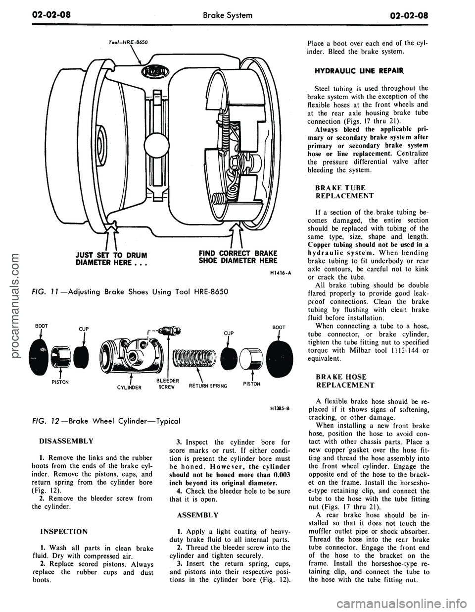
1.
Use Rotunda Tool HRE 8650,
(Fig. 11) to determine the inside diam-
eter of the drum braking surface.
2.
Reverse the tool as shown in Fig.
11 and adjust the brake shoe diameter
to fit the gauge. Hold the automatic
adjusting lever out of engagement
while rotating the adjusting screw, to
prevent burring the screw slots. Make
sure the adjusting screw rotates freely.
If necessary, lubricate the adjusting
screw threads with a thin, uniform
coating of MIC-100-A.
3.
Rotate Tool HRE 8650 around
the brake shoes to be sure of the set-
ting.
4.
Apply a small quantity of high
temperature grease to the points
where the shoes contact the backing
plate, being careful not to get the lu-
bricant on the linings.
5. Install the drums. Install Tinner-
man nuts and tighten securely.
6. Install the wheels on the drums
and tighten the nuts to specification.
7.
Complete the adjustment by
applying the brakes several times with
a minimum of 50 lbs pressure on the
pedal while backing the vehicle. After
each stop the vehicle must be moved
forward.
8. After the brake shoes have been
properly adjusted, check the operation
of the brakes by making several stops
while operating in a forward direction.
WHEEL CYLINDER REPAIR-
DRUM BRAKE
Wheel cylinders should not be di-
sassembled unless they are leaking or
unless new cups and boots are to be
installed. It is not necessary to remove
the brake cylinder from the backing
plate to disassemble, inspect, or hone
and overhaul the cylinder. Removal is
necessary only when the cylinder is
damaged or scored beyond repair.procarmanuals.com
Page 27 of 413
02-02-08
Brake System
02-02-08
Tool-HRE-8650
JUST SET TO DRUM
DIAMETER HERE . . .
FIND CORRECT BRAKE
SHOE DIAMETER HERE
H1416-A
FIG.
7
7—Adjusting Brake Shoes Using Tool HRE-8650
BOOT
BOOT
PISTON
. BLEEDER .
CYLINDER
SCREW RETURN SPRING PIST0N
H1385-B
FIG. 72—Brake Wheel Cylinder—Typical
DISASSEMBLY
1.
Remove the links and the rubber
boots from the ends of the brake cyl-
inder. Remove the pistons, cups, and
return spring from the cylinder bore
(Fig. 12).
2.
Remove the bleeder screw from
the cylinder.
INSPECTION
1.
Wash all parts in clean brake
fluid. Dry with compressed air.
2.
Replace scored pistons. Always
replace the rubber cups and dust
boots.
3.
Inspect the cylinder bore for
score marks or rust. If either condi-
tion is present the cylinder bore must
be honed. However, the cylinder
should not be honed more than 0.003
inch beyond its original diameter.
4.
Check the bleeder hole to be sure
that it is open.
ASSEMBLY
1.
Apply a light coating of heavy-
duty brake fluip! to all internal parts.
2.
Thread the bleeder screw into the
cylinder and tighten securely.
3.
Insert the return spring, cups,
and pistons into their respective posi-
tions in the cylinder bore (Fig. 12).
Place a boot over each end of the cyl-
inder. Bleed the brake system.
HYDRAULIC LINE REPAIR
Steel tubing is used throughout the
brake system with the exception of the
flexible hoses at the front wheels and
at the fear axle housing brake tube
connection (Figs. 17 thru 21).
Always bleed the applicable pri-
mary or secondary brake system after
primary or secondary brake system
hose or line replacement. Centralize
the pressure differential valve after
bleeding the system.
BRAKE TUBE
REPLACEMENT
If a section of the brake tubing be-
comes damaged, the entire section
should be replaced with tubing of the
same type, size, shape and length.
Copper tubing should not be used in a
hydraulic system. When bending
brake tubing to fit underbody or rear
axle contours, be careful not to kink
or crack the tube.
All brake tubing should be double
flared properly to provide good leak-
proof connections. Clean the brake
tubing by flushing with clean brake
fluid before installation.
When connecting a tube to a hose,
tube connector, or brake cylinder,
tighten the tube fitting nut to specified
torque with Milbar tool 1112-144 or
equivalent.
BRAKE HOSE
REPLACEMENT
A flexible brake hose should be re-
placed if it shows signs of softening,
cracking, or other damage.
When installing a new front brake
hose,
position the hose to avoid con-
tact with other chassis parts. Place a
new copper gasket over the hose fit-
ting and thread the hose assembly into
the front wheel cylinder. Engage the
opposite end of the hose to the brack-
et on the frame. Install the horsesho-
e-type retaining clip, and connect the
tube to the hose with the tube fitting
nut (Figs. 17 thru 21).
A rear brake hose should be in-
stalled so that it does not touch the
muffler outlet pipe or shock absorber.
Thread the hose into the rear brake
tube connector. Engage the front end
of the hose to the bracket on the
frame. Install the horseshoe-type re-
taining clip, and connect the tube to
the hose with the tube fitting nut.procarmanuals.com
Page 36 of 413
02-02-17
Brake System
02-02-17
CALIPER PARTS
2B120 R.H.
2B121 L.H.
CALIPER ASS'Y
2B118 R.H.
2BU9L.H.
INSULATOR
CUP
2B2"
2B164
STABILIZER
2B295
FAIRLANE, MONTEGO, FALCON,
MUSTANG AND COUGAR
SEAL
2B115
2207
BOOT
20310-S
34806 S \ INNER BEARING
w CONE AND ROLLER
1201
CUP
ANCHOR PLATE
2B293 L.H.
2B292 R.H.
CONE AND ROLLER
1216
GREASE SEAL
1190
ADJUSTING NUT
374504-S
3105-R.H.
3106-L.H.
ROTOR SPLASH SHI
2K004-R.H.
2K005-L.H.
COVER-1130
1102
H 1670-A
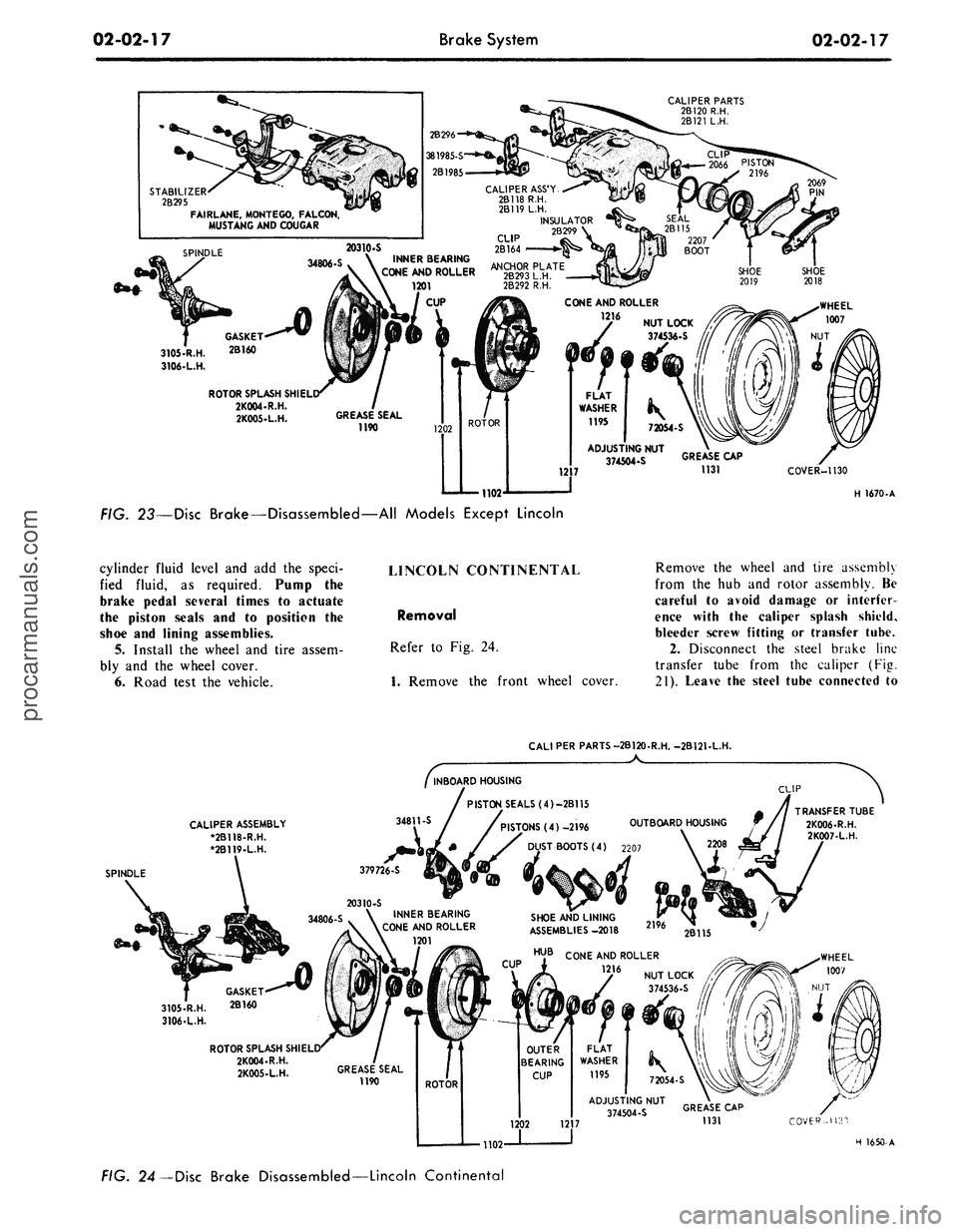
FIG. 23—Disc Brake—Disassembled—All Models Except Lincoln
cylinder fluid level and add the speci-
fied fluid, as required. Pump the
brake pedal several times to actuate
the piston seals and to position the
shoe and lining assemblies.
5. Install the wheel and tire assem-
bly and the wheel cover.
6. Road test the vehicle.
LINCOLN CONTINENTAL
Removal
Refer to Fig. 24.
1.
Remove the front wheel cover.
Remove the wheel and tire assembly
from the hub and rotor assembly. Be
careful to avoid damage or interfer-
ence with the caliper splash shield,
bleeder screw fitting or transfer tube.
2.
Disconnect the steel brake line
transfer tube from the caliper (Fig.
21).
Leave the steel tube connected to
CALI PER PARTS-2B120-R.H. -2B121-L.H.
CALIPER ASSEMBLY
*2B118-R.H.
•2B119-L.H.
34811-S
SPINDLE
379726-S
INBOARD HOUSING
PISTON SEALS (4)-2B115
/PISTONS (4) -2196 OUTBOARD HOUSING
T BOOTS (4) 2207
CLIP
34806-S
INNER BEARING
CONE AND ROLLER
1201
GASKET
3105-R.H.
2B16°
3106-L.H.
ROTOR SPLASH
SHI
EL
1102
SHOE AND LINING
ASSEMBLIES -2018
COVER-US'!
H 1650-A
FIG. 24—Disc Brake Disassembled—Lincoln Continentalprocarmanuals.com
Page 39 of 413
02-02-20
Brake System
02-02-20
1.
Disconnect the stoplight switch
wires at the connector. Remove the
spring retainer. Slide the stop light
switch off the brake pedal pin just far
enough to clear the end of the pin,
then liftfthe switch straight upward
from the pin. Use care to avoid switch
damage during removal.
2.
Slide the master cylinder push
rod and the nylon washers and bush-
ings off the brake pedal pin.
3.
Remove the brake tube from the
primary and secondary outlet ports of
the master cylinder.
4.
Remove the cap screws and lock-
washers that secure the master cylin-
der to the dirSh panel and lift the cyl-
inder forward and upward from the
vehicle.
Installation
1.
Position the boot on the push
rod and secure the boot to the master
cylinder. Carefully insert the master
cylinder push rod and boot through
the dash panel opening and position
the master cylinder on the panel.
2.
Install the cap screws at the dash
panel and torque them to specifica-
tion.
3.
Coat the nylon bushings with
SAE 10W oil. Install the nylon wash-
er and bushing on the brake pedal pin.
4.
Position the stop light switch on
the brake pedal pin, install the nylon
bushing and washer and secure them
in position with the spring retainer.
5.
Connect the wires at the stop
light switch connector.
6. Connect the brake lines to the
master cylinder leaving the brake line
fittings loose.
7.
Fill the master cylinder with the
specified brake fluid to within 1/4
inch of the top of the dual reservoirs.
Use Ford Brake Fluid— Extra Heavy
Duty-Part Number C6AZ-19542-A
(ESA-M6C25-A) or equivalent for all
drum brake applications. The extra
heavy duty brake system fluid is col-
ored blue for identification. Do not
mix low temperature brake fluids with
the specified fluid for the power disc
brake system.
8. Bleed the dual-master cylinder
and the primary and secondary brake
systems. Centralize the pressure dif-
ferential valve. Refer to Hydraulic
System Bleeding and Centralizing of
the Differential Valve, Part 2-1, Sec-
tion 2 for proper procedure.
9. Operate the brakes several times,
then check for external hydraulic
leaks.
FAIRLANE, MONTEGO,
FALCON, MUSTANG AND
COUGAR
Removal
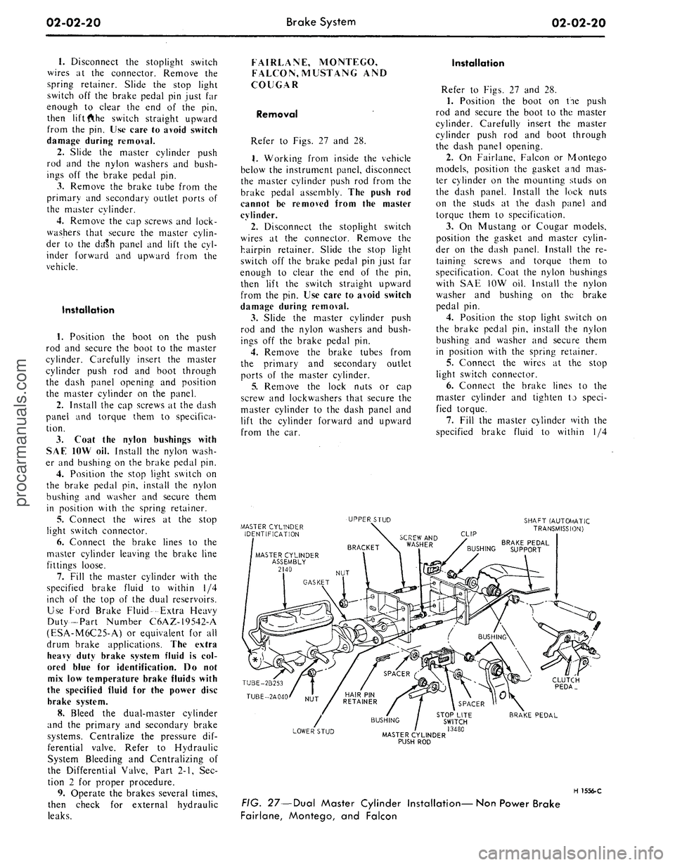
Refer to Figs. 27 and 28.
1.
Working from inside the vehicle
below the instrument panel, disconnect
the master cylinder push rod from the
brake pedal assembly. The push rod
cannot be removed from the master
cylinder.
2.
Disconnect the stoplight switch
wires at the connector. Remove the
hairpin retainer. Slide the stop light
switch off the brake pedal pin just far
enough to clear the end of the pin,
then lift the switch straight upward
from the pin. Use care to avoid switch
damage during removal.
3.
Slide the master cylinder push
rod and the nylon washers and bush-
ings off the brake pedal pin.
4.
Remove the brake tubes from
the primary and secondary outlet
ports of the master cylinder.
5.
Remove the lock nuts or cap
screw and lockwashers that secure the
master cylinder to the dash panel and
lift the cylinder forward and upward
from the car.
Installation
Refer to Figs. 27 and 28.
1.
Position the boot on tie push
rod and secure the boot to the master
cylinder. Carefully insert the master
cylinder push rod and boot through
the dash panel opening.
2.
On Fairlane, Falcon or Montego
models, position the gasket and mas-
ter cylinder on the mounting studs on
the dash panel. Install the lock nuts
on the studs at the dash panel and
torque them to specification.
3.
On Mustang or Cougar models,
position the gasket and master cylin-
der on the dash panel. Install the re-
taining screws and torque them to
specification. Coat the nylon bushings
with SAE 10W oil. Install the nylon
washer and bushing on the brake
pedal pin.
4.
Position the stop light switch on
the brake pedal pin, install the nylon
bushing and washer and secure them
in position with the spring retainer.
5.
Connect the wires at the stop
light switch connector.
6. Connect the brake lines to the
master cylinder and tighten to speci-
fied torque.
7.
Fill the master cylinder with the
specified brake fluid to within 1/4
MASTER CYLINDER
IDENTIFICATION
UPPER STUD
SHAFT (AUTOf/lATIC
TRANSMISSION)
CLIP
BRAKE PEDAL
BUSHING SUPPORT
TUBE-2B253
TUBE-2A040
CLUTCH
PEDA_
LOWER STUD
STOP LITE
SWITCH
/ 13480
MASTER CYLINDER
PUSH ROD
BRAKE PEDAL
H 1556-C
FIG. 27—Dual Master Cylinder Installation—Non Power Brake
Fairlane, Montego, and Falconprocarmanuals.com
Page 43 of 413
02-02-24
Brake
System
02-02-24
proportioning valve to the fender
apron and remove the proportioning
valve.
Installation
1.
Position the proportioning valve
to the fender apron.
2.
Connect the two brake lines at
the proportioning valve. Do not tight-
en.
3.
Install the bolt retaining the pro-
portioning valve to the fender apron.
4.
Tighten the brake line tube nuts
at the proportioning valve to specifica-
tions.
5.
Bleed the brakes and centralize
pressure differential valve.
THUNDERBIRD AND
CONTINENTAL MARK III
Removal
Refer to Fig. 20.
1.
Disconnect the two hydraulic
brake lines at the master cylinder.
2.
Remove the two nuts retaining
the master cylinder to the booster and
remove the master cylinder for clear-
ance.
3.
Disconnect the two brake lines at
the proportioning valve.
4.
Remove the bolt and nut retain-
ing the proportioning valve to the
pressure differential valve bracket and
remove the proportioning valve assem-
bly.
Installation
1.
Transfer the bracket to the new
proportioning valve.
2.
Position the proportioning valve
assembly to the pressure differential
valve bracket.
3.
Connect the two brake lines to
the proportioning valve. Do not tight-
en.
4.
Install the bolt and nut retaining
the proportioning valve to the pressure
differential valve bracket.
5.
Tighten the two brake line tube
nuts at the proportioning valve to
specifications.
6. Position the master cylinder to
the booster and install the nuts retain-
ing the master cylinder to the booster.
7.
Connect the two brake lines at
the master cylinder and tighten the
tube nuts to specifications.
8. Bleed the brakes and centralize
the pressure differential valve.
LINCOLN CONTINENTAL
Removal
Refer to Fig. 21.
1.
Disconnect the two brake lines at
the proportioning valve.
2.
Loosen the bolt and nut on the
bracket retaining the proportioning
valve to the chassis.
3.
Remove the proportioning valve
from the bracket.
Installation
- 1. Position the proportioning valve
in the bracket and connect the two
brake lines. Do not tighten.
2.
Tighten the bolt and nut on the
bracket.
3.
Tighten the tube nuts on the
brake lines at the proportioning valve
to specifications.
4.
Bleed the brakes and centralize
the pressure differential valve.
PRESSURE METERING VALVE—
LINCOLN CONTINENTAL
REMOVAL
Refer to Fig. 21.
1.
Loosen the tube nuts connecting
the inlet and outlet tubes at the me-
tering valve, and remove the tubes.
2.
Remove the two screws retaining
the metering valve to the frame
crossmember, and remove the me-
tering valve. The metering valve is ser-
viced as an assembly only.
INSTALLATION
1.
Position the metering valve to
the frame crossmember, and install
the retaining screws.
2.
Connect the inlet and outlet
tubes to the metering valve, and tight-
en the tube nuts to specification.
BRAKE BOOSTER
REMOVAL
1.
Working from inside the\ vehicle
below the instrument panel, disconnect
the booster push rod from the brake
pedal assembly. To do this, proceed as
follows:
Disconnect the stop light switch
wires at the connector. Remove the
hairpin retainer. Slide the stop light
switch off from the brake pedal pin
just far enough for the switch outer
hole to clear the pin, and then remove
the switch from the pin and booster
push rod. Be careful not to damage
the switch during removal. Slide the
booster push rod and the nylon wash-
ers and bushing off the brake pedal
pin (Figs. 29 thru 33).
2.
Open the hood and remove the
master cylinder from the booster. Se-
cure it to one side without disturbing
the hydraulic lines. It is not necessary
to disconnect the brake lines, but care
should be taken that the brake lines
are not deformed. Permanent defor-
mation of brake lines can lead to tube
failure.
3.
Disconnect the manifold vacuum
hose or hoses from the booster unit.
4.
Remove the booster-to-dash
panel attaching nuts or bolts (Figs. 29
thru 33). Remove the booster and
bracket assembly from the dash panel,
sliding the push rod link out from the
engine side of the dash panel.
5.
On Fairlane, Montego, and Fal-
con models, remove the push rod link
boot from the dash panel.
INSTALLATION
1.
On Fairlane, Montego and Fal-
con models, install the push rod link
boot in the hole in the dash panel as
shown in Fig. 23. Install the four
spacers on the mounting studs.
2.
Mount the booster and bracket
assembly to the dash panel by insert-
ing the push rod or push rod link in
through the hole and boot in the dash
panel. Install the bracket-to-dash
panel attaching lock nuts or bolts
(Figs.
29 thru 33).
3.
Connect the manifold vacuum
hose or hoses to the booster.
4.
Before installing the master cyl-
inder, check the distance from the
outer end of the booster assembly
push rod to master cylinder surface.
Turn the screw in or out to obtain the
specified length. Refer to Part 2-1,
Section 2, Power Brake Master Cylin-
der Push Rod Adjustment. Install the
master cylinder and torque the attach-
ing nuts to specifications.
5.
Working from inside the vehicle
below the instrument panel, connect
the booster push rod link to the brake
pedal assembly. To do this, proceed as
follows:
Install the inner nylon washer, the
booster push rod, and the bushing on
the brake pedal pin. Position the
switch so that it straddles the push
rod with the switch slot on the pedal
pin and the switch outer hole justprocarmanuals.com
Page 58 of 413
02-02-39
Brake System
02-02-39
MAJOR REPAIR OPERATIONS
BRAKE DRUM REFINISHING
Minor scores on a brake drum can
be removed with sandpaper. A drum
that is excessively scored or shows a
total indicator runout of over 0.007
inch should be turned down. Remove
only enough stock to eliminate the
scores and true up the drum. The refi-
nished diameter must not exceed 0.060
inch oversize.
Check the inside diameter of the
brake drum with a brake drum mi-
crometer (Tool FRE-14^1).
If the drum diameter is less than
0.030 inch oversize after refinishing^
standard lining may be installed. If
the drum diameter is 0.030—0.060
inch oversize after refinishing, oversize
lining must be installed.
After a drum is turned down, wipe
the refinished surface with a cloth
soaked in clean denatured alcohol. If
one drum is turned down, the opposite
drum on the same axle should also be
cut down to the same size.
ROTOR REFINISHING
Rotunda Disc Brake Attachment,
FRE-2249-2, is the only recommended
tool to refinish the disc brake rotors.
The step-by-step resurfacing procedure
provided with the tool must be ad-
hered to.
The finished braking surfaces of the
rotor must be flat and parallel within
0.0007 inch; lateral runout must not
exceed 0.003 inch total indicator read-
ing, and the surface finish of the brak-
ing surfaces are to be 80/15 micro
inches. The minimum limiting dimen-
sions (Figs. 11 and 12, Part 2-1) from
the inboard bearing cup to the out-
board rotor face and from the inboard
bearing cup to the inboard rotor face
must be observed when removing ma-
terial from the rotor braking surfaces.
On all models except Lincoln Con-
tinental, the limiting dimensions are to
be measured with a ball and gage bar
(Rotunda Kit FRE-70160).
BRAKE SHOE RELINING
Brake linings that are worn to with-
in 1/32 inch of the rivet head or are
less than 0.030 inch thick (bonded lin-
ing) or have been contaminated with
brake fluid, grease or oil must be re-
placed. Failure to replace worn linings
will result in a scored drum. When it
is necessary to replace linings, they
must also be replaced on the wheel on
the opposite side of the vehicle.
Inspect brake shoes for distortion,
cracks, or looseness. If this condition
exists,
the shoe must be discarded. Do
not attempt to repair a defective brake
shoe.
1.
Wash the brake shoes thoroughly
in a clean solvent. Remove all burrs
or rough spots from the shoes.
2.
Check the inside diameter of the
brake drum with a brake drum mi-
crometer (tool FRE-1431). If the di-
ameter is less than 0.030 inches over-
size,
standard lining may be installed.
If the diameter is 0.030—0.060 inches
oversize, oversize lining should be in-
stalled.
3.
Position the new lining on the
shoe.
Starting in the center, insert and
secure the rivets, working alternately
towards each end. Replacement lin-
ings are ground and no further grind-
ing is required.
4.
Check the clearance between the
shoe and lining. The lining must seat
tightly against the shoe with not more
than 0.008 inch clearance between any
two rivets.
RETAINER - 2B245
DUAL MASTER CYLINDER
DISASSEMBLY
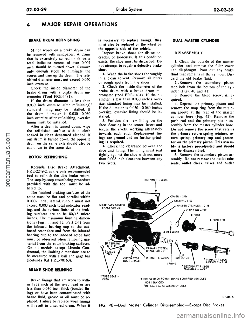
1.
Clean the outside of the master
cylinder and remove the filler cover
and diaphragm. Pour out any brake
fluid that remains in the cylinder. Dis-
card the old brake fluid.
2.*
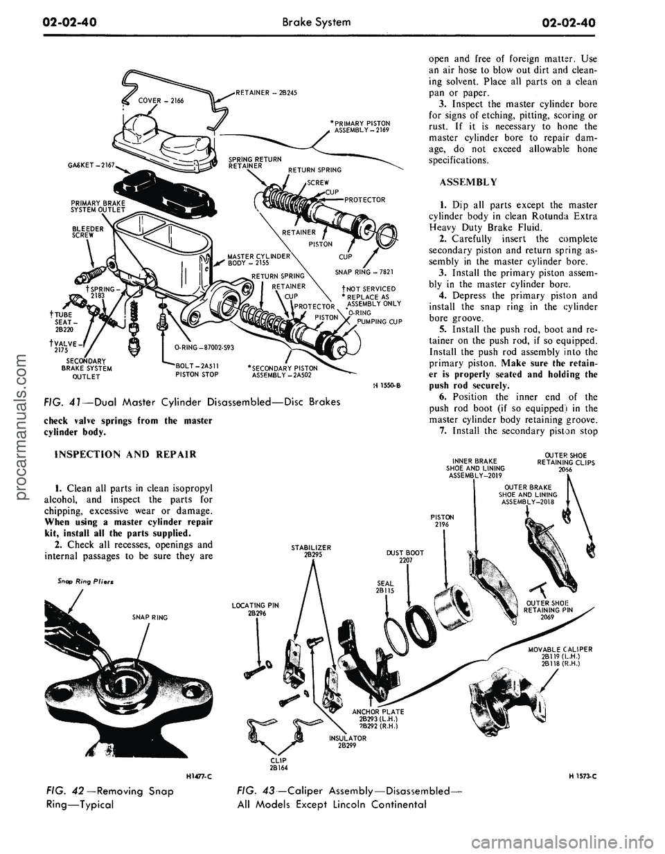
Remove the secondary piston
stop bolt from the bottom of the cyl-
inder (Figs. 40 and 41).
3.
Remove the bleed screw, iL re-
quired.
4.
Depress the primary piston and
remove the snap ring from the retain-
ing groove at the rear of the master
cylinder bore (Fig. 42). Remove the
push rod and the primary piston as-
sembly from the master cylinder bore.
Do not remove the screw that retains
the primary return spring retainer, re-
turn spring, primary cup and protec-
tor on the primary piston. This assem-
bly is factory pre-adjusted and should
not be disassembled.
5.
Remove the secondary piston as-
sembly. Do not remove the outlet tube
seats,
outlet check valves and outlet
SECONDARY SYSTEM
BRAKE OUTLET
COVER -2166
GASKET-2167
MASTER CYLINDER -2155
SNAP RING -7821
BOOT
PUSH ROD
PRIMARY PISTON
ASSEMBLY - 2169
tTUBE SEAT-
2B220
* SECONDARY PISTON
ASSEMBLY - 2A502
• NOT USED ON POWER BRAKE EQUIPPED VEHICLES
fNOT SERVICED
•REPLACE AS AN ASSEMBLY ONLY
H 1499-B
FIG. 40— Dual Master Cylinder Disassembled—Except Disc Brakesprocarmanuals.com
Page 59 of 413
02-02-40
Brake System
02-02-40
RETAINER - 2B245
PRIMARY PISTON
ASSEMBLY-2169
GASKET-2167
RETURN SPRING
RETAINER
\ CUP
\\PROTECTOR
^\i # PISTON
fNOT SERVICED
* REPLACE AS
ASSEMBLY ONLY
*O-RING
PUMPING CUP
tVALVE
2175
SECONDARY
BRAKE SYSTEM
OUTLET
*SECONDARY PISTON
ASSEMBLY-2A502
H 1550-B
FIG. 41—Dual Master Cylinder Disassembled—Disc Brakes
check valve springs from the master
cylinder body.
open and free of foreign matter. Use
an air hose to blow out dirt and clean-
ing solvent. Place all parts on a clean
pan or paper.
3.
Inspect the master cylinder bore
for signs of etching, pitting, scoring or
rust. If it is necessary to hone the
master cylinder bore to repair dam-
age,
do not exceed allowable hone
specifications.
ASSEMBLY
1.
Dip all parts except the master
cylinder body in clean Rotunda Extra
Heavy Duty Brake Fluid.
2.
Carefully insert the complete
secondary piston and return spring as-
sembly in the master cylinder bore.
3.
Install the primary piston assem-
bly in the master cylinder bore.
4.
Depress the primary piston and
install the snap ring in the cylinder
bore groove.
5.
Install the push rod, boot and re-
tainer on the push rod, if so equipped.
Install the push rod assembly into the
primary piston. Make sure the retain-
er is properly seated and holding the
push rod securely.
6. Position the inner end of the
push rod boot (if so equipped) in the
master cylinder body retaining groove.
7.
Install the secondary piston stop
INSPECTION AND REPAIR
1.
Clean all parts in clean isopropyl
alcohol, and inspect the parts for
chipping, excessive wear or damage.
When using a master cylinder repair
kit, install all the parts supplied.
2.
Check all recesses, openings and
internal passages to be sure they are
Snap Ring Pliers
SNAP RING
H1477-C
FIG. 42—Removing Snap
Ring—Typical
INNER BRAKE
SHOE AND LINING
ASSEMBLY-2019
OUTER SHOE
RETAINING CLIPS
2066
STABILIZER
2B295
LOCATING PIN
2B296
ANCHOR PLATE
2B293(L.H.)
2B292 (R.H.)
MOVABLE CALIPER
2B119(L.H.)
2B118(R.H.)
H 1573-C
FIG. 43—Caliper Assembly—Disassembled-
All Models Except Lincoln Continentalprocarmanuals.com