automatic FORD MUSTANG 1969 Volume One Chassis
[x] Cancel search | Manufacturer: FORD, Model Year: 1969, Model line: MUSTANG, Model: FORD MUSTANG 1969Pages: 413, PDF Size: 75.81 MB
Page 6 of 413
01-01-02
Vehicle Identification
01-01-02
VEHICLE WARRANTY NUMBER
The vehicle warranty number is the first line of numbers and
letters appearing on the Warranty Plates (Fig. 1). The Warranty
Plate is riveted to the left front door lock face panel. The first
number indicates the model year. The letter following the model
year number indicates the manufacturing assembly plant. The next
two numbers designate the Body Serial Code followed by a letter
expressing the Engine Code. The group of six digits remaining on
the first line indicate the Consecutive Unit Number.
VEHICLE DATA
The vehicle data appears on the second or lower line on the
Warranty Plate. The first two numbers and a letter identify the
Body Style. A letter or a number appears next indicating the
Exterior Paint Color followed by a number-letter combination
designating the Interior Trim. To the right of this code appears the
Date Code indicating the date the car was manufactured. A two-
digit number next designates the district in which the car was
ordered and may appear in conjunction with a Domestic Special
Order or Foreign Special Order number when applicable. The final
two spaces indicate the Rear Axle Ratio (numbers for regular axles,
letters for locking-types) and the Transmission type (numbers for
manual,
letters for automatic).
OFFICIAL VEHICLE IDENTIFICATION NUMBER
The official Vehicle Identification Number (VIN) for title and
registration purposes is stamped on an aluminum tab that is riveted
to the instrument panel close to the windshield on the driver's side
of the car and is visible from outside (Fig. 2).
MODEL YEAR CODE
The number 9 designates 1969.
ASSEMBLY PLANT CODES
COUGAR
Code
Letter
Code
Letter
A
B
C
D
E
F
G
H
J
K
Atlanta
L
Oakville (Canada)
N
Ontario Truck
P
Dallas
R
.,
Mahwah
S
Dearborn
T
Chicago
U
Lorain
W
Los Angeles
X
Kansas City
Y
Z
Michigan Truck
Norfolk
Twin Cities
San Jose
.
(Pilot). ...Allen Park
Metuchen
Louisville
Wayne
St. Thomas
Wixom
St. Louis
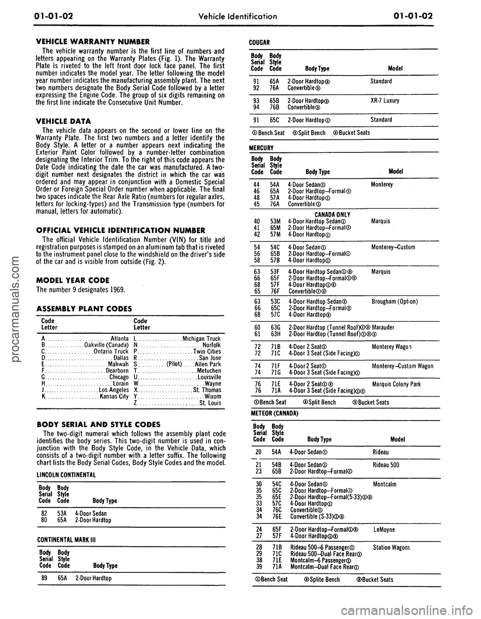
BODY SERIAL AND STYLE CODES
The two-digit numeral which follows the assembly plant code
identifies the body series. This two-digit number is used in con-
junction with the Body Style Code, in the Vehicle Data, which
consists of a two-digit number with a letter suffix. The following
chart lists the Body Serial Codes, Body Style Codes and the model.
LINCOLN CONTINENTAL
Body Body
Serial Style
Code Code Body Type
82
53A
4-Door Sedan
80
65A
2-Door
Hardtop
CONTINENTAL MARK
III
Body Body
Serial Style
Code Code Body Type
89
65A
2-Door
Hardtop
Body
Serial
Code
91
92
93
94
91
Body
Style
Code
65A
76A
65B
76B
65C
® Bench Seat
MERCURY
Body
Serial
Code
44
46
48
45
40
41
42
54
56
58
63
66
68
65
63
66
68
60
61
72
72
74
74
76
76
Body
Style
Code
54A
65A
57A
76A
53M
65M
57M
54C
65B
57B
53F
65F
57 F
76F
53C
65C
57C
63G
63H
71B
71C
71F
71G
71E
71A
©Bench Seat
Body
Type
2-Door
Hardtop©
Convertible©
2-Door
Hardtop©
Convertible®
2-Door
Hardtop®
Model
Standard
XR-7 Luxury
Standard
©Split Bench ©Bucket Seats
Body Type
4-Door Sedan©
2-Door
Hardtop-Formal®
4-Door Hardtop®
Convertible®
CANADA ONLY
4-Door Hardtop Sedan®
2-Door
Hardtop-Formal®
4-Door Hardtop®
4-Door Sedan®
2-Door
Hardtop-Formal®
4-Door Hardtop®
4-Door Hardtop Sedan®©
2-Door
Hardtop-Formal®©
4-Door Hardtop®®
Convertible®®
4-Door Hardtop Sedan©
2-Door
Hardtop-Formal©
4-Door Hardtop©
Model
Monterey
Marquis
Monterey-Custom
Marquis
Brougham (Option)
2-Door
Hardtop (Tunnel Roof)®© Marauder
2-Door
Hardtop (Tunnel Roof)®®©
4-Door 2 Seat®
4-Door 3 Seat (Side Facing)®
4-Door
2
Seat®
4-Door 3 Seat (Side Facing)®
4-Door 2 Seat®©
4-Door 3 Seat (Side Facing)®©
Monterey Wagoi
Monterey-Custom Wagon
Marquis Colony Park
©Split Bench ©Bucket Seats
METEOR (CANADA)
Body
Serial
Code
20
21
23
Body
Style
Code
54A
54B
65B
Body Type
4-Door Sedan®
4-Door Sedan®
2-Door
Hardtop-Formal®
Model
Rideau
Rideau 500
30
54C
4-Door Sedan®
35
65C
2-Door
Hardtop-Formal®
35
65E
2-Door
Hardtop-Formal{5-33)®®
33
57C
4-Door Hardtop®
34
76C
Convertible®
34
76E
Convertible (S-33)®®
Montcalm
24
65F
2-Door
Hardtop-Formal®©
27
57F
4-Door Hardtop®®
LeMoyne
28
71B
Rideau 500-6 Passenger®
29
71C
Rideau 500-Dual Face Rear®
38
71E
Mo ntcalm-6 Passenger®
39
71A
Montcalm-Dual Face Rear®
Station Wagons.
©Bench Seat ©Splite Bench ©Bucket Seatsprocarmanuals.com
Page 8 of 413
01-01-04
Vehicle Identification
01-01-04
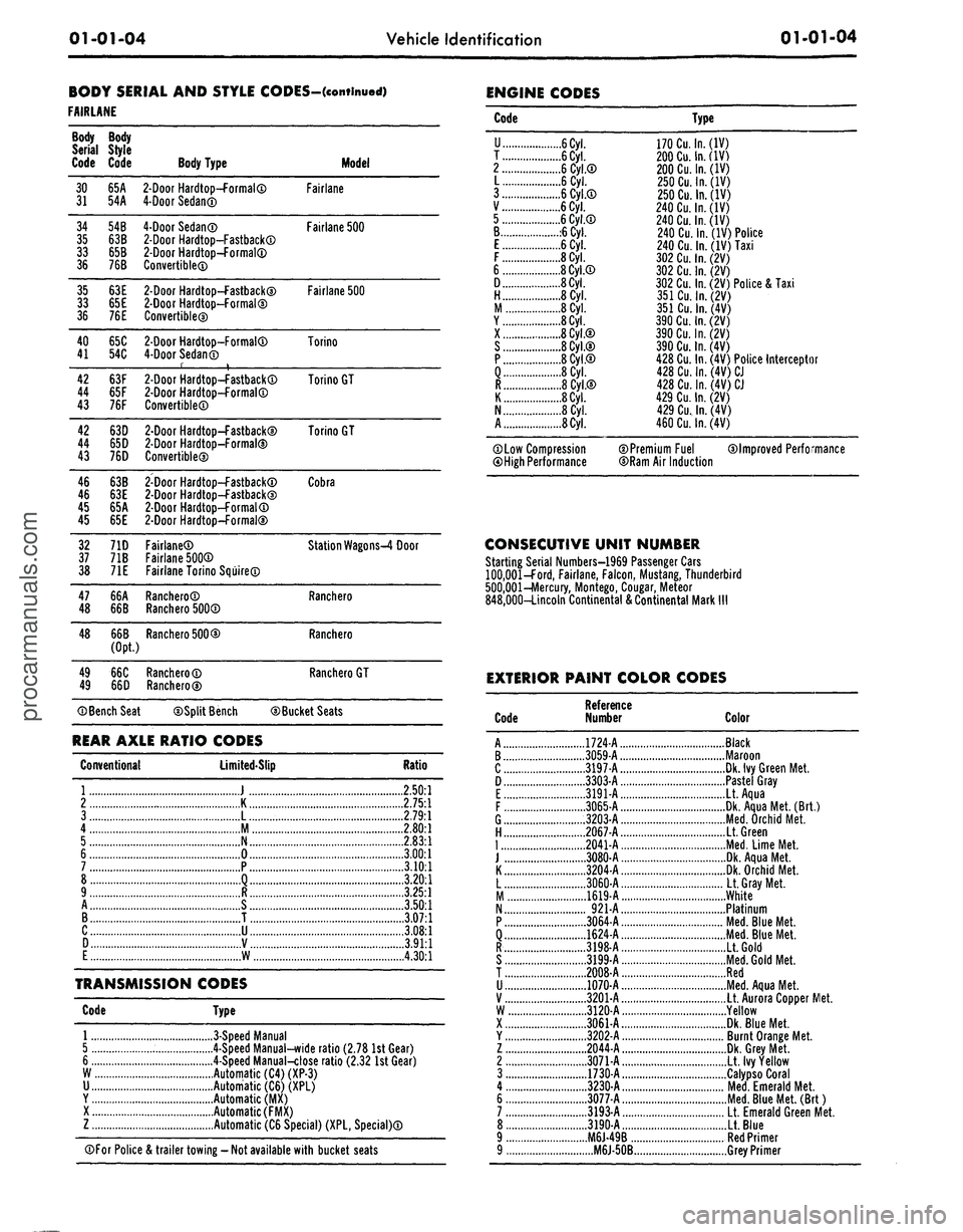
BODY SERIAL AND STYLE CODES-(continued)
FAIRLANE
Body
Serial
Code
30
31
34
35
33
36
35
33
36
40
41
42
44
43
42
44
43
46
46
45
45
32
37
38
47
48
48
49
49
Body
Style
Code
65A
54A
54B
63B
65B
76B
63E
65E
76E
65C
54C
63F
65F
76F
63D
65D
76D
63B
63E
65A
65E
71D
71B
71E
66A
66B
66B
(Opt.)
66C
66D
©Bench Seat
Body Type
2-Door
Hardtop-formal®
4-Door
Sedan®
4-Door
Sedan®
2-Door
Hardtop—Fastback®
2-Door
Hardtop-formal®
Convertible®
2-Door
Hardtop—Fastback©
2-Door
Hardtop-Formal©
Convertible®
2-Door
Hardtop-Formal®
4-Door
Sedan®
r t
2-Door
Hardtop—FastbackCD
2-Door
Hardtop-Formal®
Convertible®
2-Door
Hardtop—Fastback®
2-Door
Hardtop-Formal®
Convertible®
2-Door
Hardtop-Fastback®
2-Door
Hardtop-Fastback®
2-Door
Hardtop-Formal®
2-Door
Hardtop-formal®
Fairlane®
Fairlane 500®
Fairlane Torino Squire®
Ranchero®
Ranchero 500®
Ranchero 500®
Ranchero®
Ranchero®
Model
Fairlane
Fairlane 500
Fairlane 500
Torino
Torino GT
Torino GT
Cobra
Station Wagons-4 Door
Ranchero
Ranchero
Ranchero GT
©Split Bench ©Bucket Seats
REAR AXLE RATIO CODES
Conventional
Limited-Slip
Ratio
1
J
2.50:1
2
K
2.75:1
3
L
2.79:1
4
M 2.801
5
N
2.83:1
6
0
3.00:1
7
P
3.10:1
8
Q
3.20:1
9
R
3.25:1
A
S
3.50:1
B
T
3.07:1
C
U
3.08:1
D
V
3.91:1
E
W
4.30:1
TRANSMISSION CODES
Code Type
1
3-Speed
Manual
5 4-Speed Manual-wide ratio (2.78 1st Gear)
6 4-Speed Manual-close ratio (2.32 1st Gear)
W Automatic (C4) (XP-3)
U Automatic (C6) (XPL)
Y Automatic (MX)
X Automatic (FMX)
Z Automatic (C6 Special) (XPL, Special)®
©For Police & trailer towing
-
Not available with bucket seats
ENGINE CODES
Code
U
6Cyl.
T
6Cyl.
2
6 Cyl.®
L 6 Cyl.
3
6 Cyl CD
V
6
Cyl."
5
.
6 Cyl CD
B .6
Cyl.
E
6
Cyl.
F
8
Cyl.
6 8 Cyl.®
D 8
Cyl.
H 8 Cyl.
M 8 Cyl.
Y 8
Cyl.
X 8 Cyl.©
S 8 Cyl.©
P 8 Cyl.®
8 Cyl.
8 Cyl.®
K 8
Cyl.
N
8
Cyl.
A 8
Cyl.
©Low Compression
©High Performance
Type
170
Cu.
In.
(IV)
200
Cu.
In.
(IV)
200
Cu.
In.
(IV)
250
Cu.
In.
(IV)
250
Cu.
In.
(IV)
240
Cu.
In.
(IV)
240
Cu.
In.
(IV)
240 Cu. In. (IV) Police
240 Cu. In. (IV) Taxi
302
Cu.
In.
(2V)
302
Cu.
In.
(2V)
302 Cu. In. (2V) Police & Taxi
351
Cu.
In.
(2V)
351
Cu.
In.
(4V)
390
Cu.
In.
(2V)
390Cu.ln.(2V)
390
Cu.
In.
(4V)
428 Cu. In. (4V) Police Interceptor
428
Cu.
In.
(4V)
CJ
428
Cu.
In.
(4V)
CJ
429
Cu.
In.
(2V)
429
Cu.
In.
(4V)
460
Cu.
In.
(4V)
©Premium Fuel ©Improved Performance
©Ram Air Induction
CONSECUTIVE UNIT NUMBER
Starting Serial Numbers—1969 Passenger Cars
100,001—Ford, Fairlane, Falcon, Mustang, Thunderbird
500,001 -Mercury, Montego,
Cougar,
Meteor
848,000—Lincoln Continental & Continental Mark
III
EXTERIOR PAINT COLOR CODES
Code
Reference
Number
Color
A
B
c
D
E
F
G
H
|
J
K
L
. .
M
N
p
Q
R
S.
.. .
T
u
v
W
X
Y
z
2.
..
3
4
6.
. .
7
8
..
1724-A
1
3059-A
3197-A
3303-A
3191-A
3065-A
. .
3203-A
..
,.2067-A
2041-A
3080-A
3204-A
3060-A
1619-A
..
921-A
3064-A
1624-A
3198-A
. .
3199-A
2008-A
1070-A
3201-A
3120-A
3061-A
. . .
3202-A
2044-A
3071-A
. .
1730-A
3230-A
.
3077-A
3193-A
3190-A
..M6J-49B..
....M6J-50B.
Black
Maroon
Dk. Ivy Green Met.
Pastel Gray
Lt. Aqua
Dk. Aqua Met. (Brt.)
Med.
Orchid Met.
Lt. Green
Med.
Lime Met.
Dk. Aqua Met.
Dk. Orchid Met.
Lt. Gray Met.
White
Platinum
Med.
Blue Met.
Med.
Blue Met.
Lt. Gold
Med.
Gold Met.
Red
Med.
Aqua Met.
Lt. Aurora Copper IVIet.
Yellow
Dk. Blue Met.
Burnt Orange Met.
Dk. Grey Met.
Lt. Ivy Yellow
Calypso Coral
Med.
Emerald Met.
Med.
Blue Met. (Brt)
Lt. Emerald Green Met.
Lt. Blue
Red Primer
Grey Primerprocarmanuals.com
Page 24 of 413
02-02-05
Brake System
02-02-05
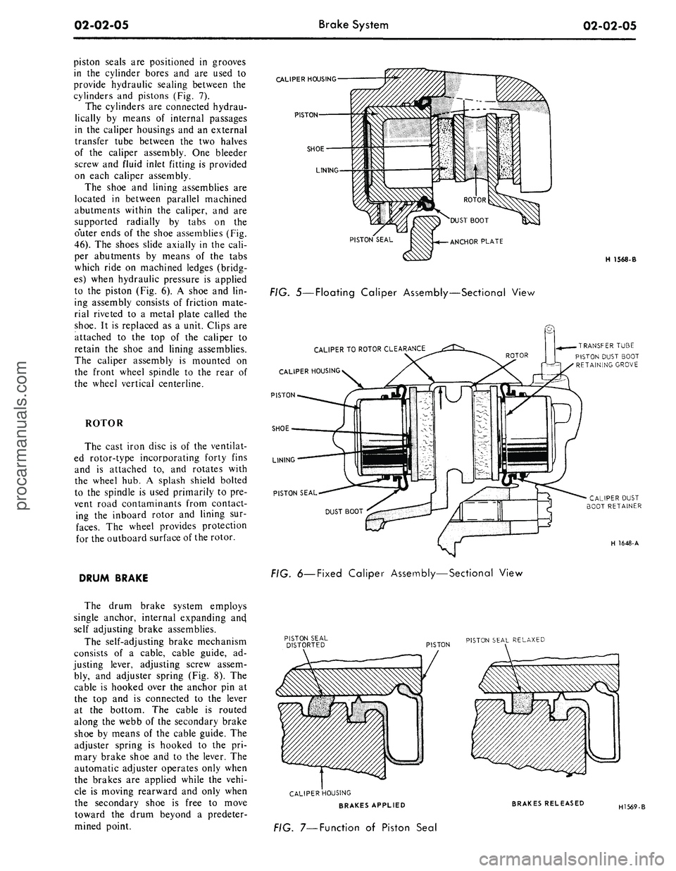
piston seals are positioned in grooves
in the cylinder bores and are used to
provide hydraulic sealing between the
cylinders and pistons (Fig. 7).
The cylinders are connected hydrau-
lically by means of internal passages
in the caliper housings and an external
transfer tube between the two halves
of the caliper assembly. One bleeder
screw and fluid inlet fitting is provided
on each caliper assembly.
The shoe and lining assemblies are
located in between parallel machined
abutments within the caliper, and are
supported radially by tabs on the
o'uter ends of the shoe assemblies (Fig.
46).
The shoes slide axially in the cali-
per abutments by means of the tabs
which ride on machined ledges (bridg-
es) when hydraulic pressure is applied
to the piston (Fig. 6). A shoe and lin-
ing assembly consists of friction mate-
rial riveted to a metal plate called the
shoe.
It is replaced as a unit. Clips are
attached to the top of the caliper to
retain the shoe and lining assemblies.
The caliper assembly is mounted on
the front wheel spindle to the rear of
the wheel vertical centerline.
ROTOR
The cast iron disc is of the ventilat-
ed rotor-type incorporating forty fins
and is attached to, and rotates with
the wheel hub. A splash shield bolted
to the spindle is used primarily to pre-
vent road contaminants from contact-
ing the inboard rotor and lining sur-
faces.
The wheel provides protection
for the outboard surface of the rotor.
DRUM BRAKE
The drum brake system employs
single anchor, internal expanding ancj
self adjusting brake assemblies.
The self-adjusting brake mechanism
consists of a cable, cable guide, ad-
justing lever, adjusting screw assem-
bly, and adjuster spring (Fig. 8). The
cable is hooked over the anchor pin at
the top and is connected to the lever
at the bottom. The cable is routed
along the webb of the secondary brake
shoe by means of the cable guide. The
adjuster spring is hooked to the pri-
mary brake shoe and to the lever. The
automatic adjuster operates only when
the brakes are applied while the vehi-
cle is moving rearward and only when
the secondary shoe is free to move
toward the drum beyond a predeter-
mined point.
CALIPER
HOUSING
PISTON
SHOE
LINING
PISTON SEAL
FIG. 5—Floating Caliper Assembly—Sectional View
CALIPER
TO
ROTOR
CLEARANCE
CALIPER
HOUSING
PISTON
SHOE
LINING
PISTON SEAL
H 1568-B
TRANSFER
TUBE
PISTON DUST BOOT
RETAINING
GROVE
CALIPER
DUST
BOOT
RETAINER
H 1648-A
FIG.
6—Fixed
Caliper Assembly—Sectional View
PISTON
PISTON SEAL
RELAXED
CALIPER
HOUSING
BRAKES APPLIED
FIG. 7—Function of Piston Seal
BRAKES RELEASED
H1569-Bprocarmanuals.com
Page 25 of 413
02-02-06
Brake
System
02-02-06
SHOE GUIDE (ANCHOR
PIN)
PLATE
SHOE GUIDE (ANCHOR
PIN)
PLATE
WASHER
PRIMARY SHOE
-TC
-ANCHOR
SPRING
PARKING
BRAKE LEVER
RETAINING
CLIP
SECONDARY
SHOE
PRIMARY
SHOE
CABLE HOOK
PARKING
BRAKE CABLE
AND HOUSING
PIVOT
NUT
AUTOMATIC
ADJUSTER
SPRING
H
1649-
A
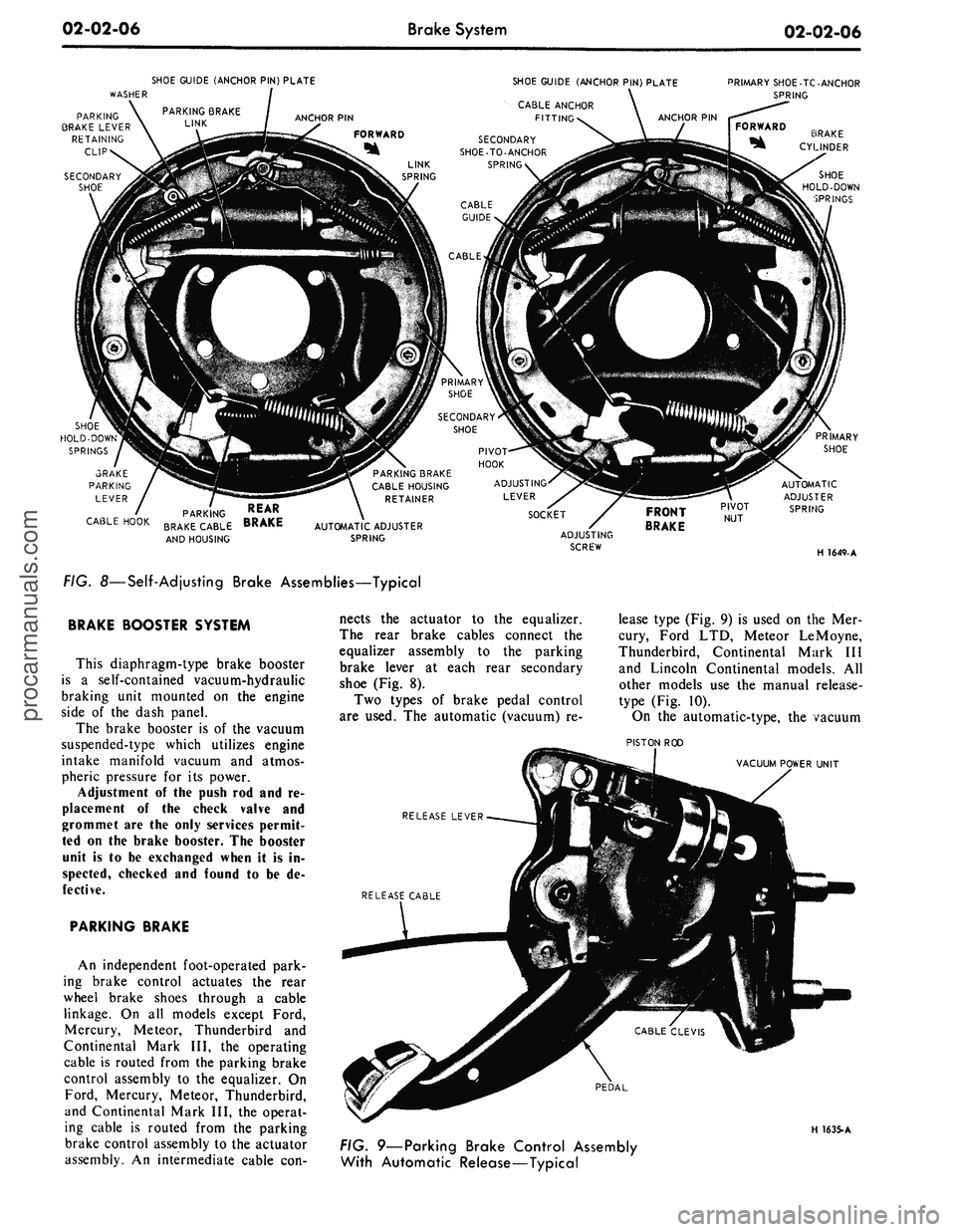
FIG. 8—Self-Adjusting Brake Assemblies—Typical
BRAKE BOOSTER SYSTEM
This diaphragm-type brake booster
is
a
self-contained vacuum-hydraulic
braking unit mounted
on the
engine
side
of the
dash panel.
The brake booster
is of the
vacuum
suspended-type which utilizes engine
intake manifold vacuum
and
atmos-
pheric pressure
for its
power.
Adjustment
of the
push
rod and re-
placement
of the
check valve
and
grommet
are the
only services permit-
ted
on the
brake booster.
The
booster
unit
is to be
exchanged when
it is in-
spected, checked
and
found
to be de-
fective.
PARKING BRAKE
An independent foot-operated park-
ing brake control actuates
the
rear
wheel brake shoes through
a
cable
linkage.
On all
models except Ford,
Mercury, Meteor, Thunderbird
and
Continental Mark
III, the
operating
cable
is
routed from
the
parking brake
control assembly
to the
equalizer.
On
Ford, Mercury, Meteor, Thunderbird,
and Continental Mark
III, the
operat-
ing cable
is
routed from
the
parking
brake control assembly
to the
actuator
assembly.
An
intermediate cable
con-
nects
the
actuator
to the
equalizer.
The rear brake cables connect
the
equalizer assembly
to the
parking
brake lever
at
each rear secondary
shoe
(Fig. 8).
Two types
of
brake pedal control
are used.
The
automatic (vacuum)
re-
lease type
(Fig. 9) is
used
on the Mer-
cury, Ford
LTD,
Meteor LeMoyne,
Thunderbird, Continental Mark
III
and Lincoln Continental models.
All
other models
use the
manual release-
type
(Fig. 10).
On
the
automatic-type,
the
vacuum
PISTON
ROD
VACUUM POWER UNIT
RELEASE LEVER
PEDAL
H 1635-A
FIG. 9—Parking Brake Control Assembly
With Automatic Release—Typicalprocarmanuals.com
Page 26 of 413
02-02-07
Brake System
02-02-07
ANTI-SKID CONTROL SYSTEM
RELEASE PAWL CAM PIN
RELEASE PAWL CAM LEVER
RELEASE CABLE
H
1636-
A
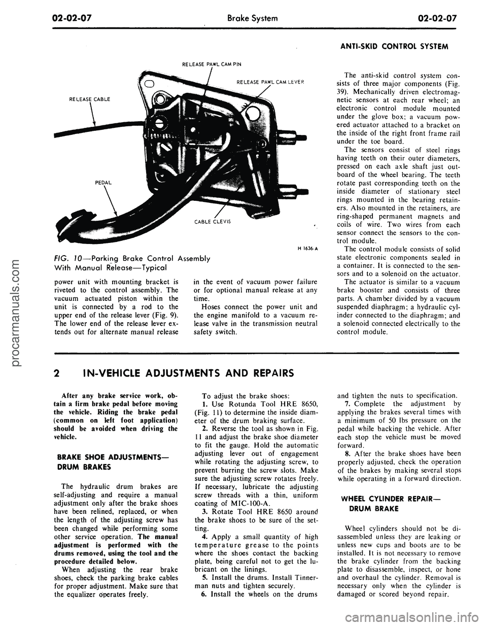
FIG. 10—Parking Brake Control Assembly
With Manual Release—Typical
power unit with mounting bracket is
riveted to the control assembly. The
vacuum actuated piston within the
unit is connected by a rod to the
upper end of the release lever (Fig. 9).
The lower end of the release lever ex-
tends out for alternate manual release
in the event of vacuum power failure
or for optional manual release at any
time.
Hoses connect the power unit and
the engine manifold to a vacuum re-
lease valve in the transmission neutral
safety switch.
The anti-skid control system con-
sists of three major components (Fig.
39).
Mechanically driven electromag-
netic sensors at each rear wheel; an
electronic control module mounted
under the glove box; a vacuum pow-
ered actuator attached to a bracket on
the inside of the right front frame rail
under the toe board.
The sensors consist of steel rings
having teeth on their outer diameters,
pressed on each axle shaft just out-
board of the wheel bearing. The teeth
rotate past corresponding teeth on the
inside diameter of stationary steel
rings mounted in the bearing retain-
ers.
Also mounted in the retainers, are
ring-shaped permanent magnets and
coils of wire. Two wires from each
sensor connect the sensors to the con-
trol module.
The control module consists of solid
state electronic components sealed in
a container. It is connected to the sen-
sors and to a solenoid on the actuator.
The actuator is similar to a vacuum
brake booster and consists of three
parts.
A chamber divided by a vacuum
suspended diaphragm; a hydraulic cyl-
inder connected to the diaphragm; and
a solenoid connected electrically to the
control module.
IN-VEHICLE ADJUSTMENTS AND REPAIRS
After any brake service work, ob-
tain a firm brake pedal before moving
the vehicle. Riding the brake pedal
(common on left foot application)
should be avoided when driving the
vehicle.
BRAKE SHOE ADJUSTMENTS—
DRUM BRAKES
The hydraulic drum brakes are
self-adjusting and require a manual
adjustment only after the brake shoes
have been relined, replaced, or when
the length of the adjusting screw has
been changed while performing some
other service operation. The manual
adjustment is performed with the
drums removed, using the tool and the
procedure detailed below.
When adjusting the rear brake
shoes,
check the parking brake cables
for proper adjustment. Make sure that
the equalizer operates freely.
To adjust the brake shoes:
1.
Use Rotunda Tool HRE 8650,
(Fig. 11) to determine the inside diam-
eter of the drum braking surface.
2.
Reverse the tool as shown in Fig.
11 and adjust the brake shoe diameter
to fit the gauge. Hold the automatic
adjusting lever out of engagement
while rotating the adjusting screw, to
prevent burring the screw slots. Make
sure the adjusting screw rotates freely.
If necessary, lubricate the adjusting
screw threads with a thin, uniform
coating of MIC-100-A.
3.
Rotate Tool HRE 8650 around
the brake shoes to be sure of the set-
ting.
4.
Apply a small quantity of high
temperature grease to the points
where the shoes contact the backing
plate, being careful not to get the lu-
bricant on the linings.
5. Install the drums. Install Tinner-
man nuts and tighten securely.
6. Install the wheels on the drums
and tighten the nuts to specification.
7.
Complete the adjustment by
applying the brakes several times with
a minimum of 50 lbs pressure on the
pedal while backing the vehicle. After
each stop the vehicle must be moved
forward.
8. After the brake shoes have been
properly adjusted, check the operation
of the brakes by making several stops
while operating in a forward direction.
WHEEL CYLINDER REPAIR-
DRUM BRAKE
Wheel cylinders should not be di-
sassembled unless they are leaking or
unless new cups and boots are to be
installed. It is not necessary to remove
the brake cylinder from the backing
plate to disassemble, inspect, or hone
and overhaul the cylinder. Removal is
necessary only when the cylinder is
damaged or scored beyond repair.procarmanuals.com
Page 28 of 413
02-02-09
Brake System
02-02-09
REMOVAL AND INSTALLATION
FRONT BRAKE DRUM
REMOVAL
1.
Raise the vehicle until the wheel
and tire clear the floor. Remove the
wheel cover or hub cap, and remove
the wheel and tire from the drum.
2.
Remove the grease cap from the
hub.
Remove the cotter pin, nut lock,
adjusting nut, and flat washer from
the spindle. Remove the outer bearing
cone and roller assembly.
3.
Pull the drum off the wheel
spindle.
4.
If the drum will not come off,
pry the rubber cover from the brake
backing plate. Insert a narrow screw-
driver through the slot and disengage
the adjusting lever from the adjusting
screw. While holding the adjusting
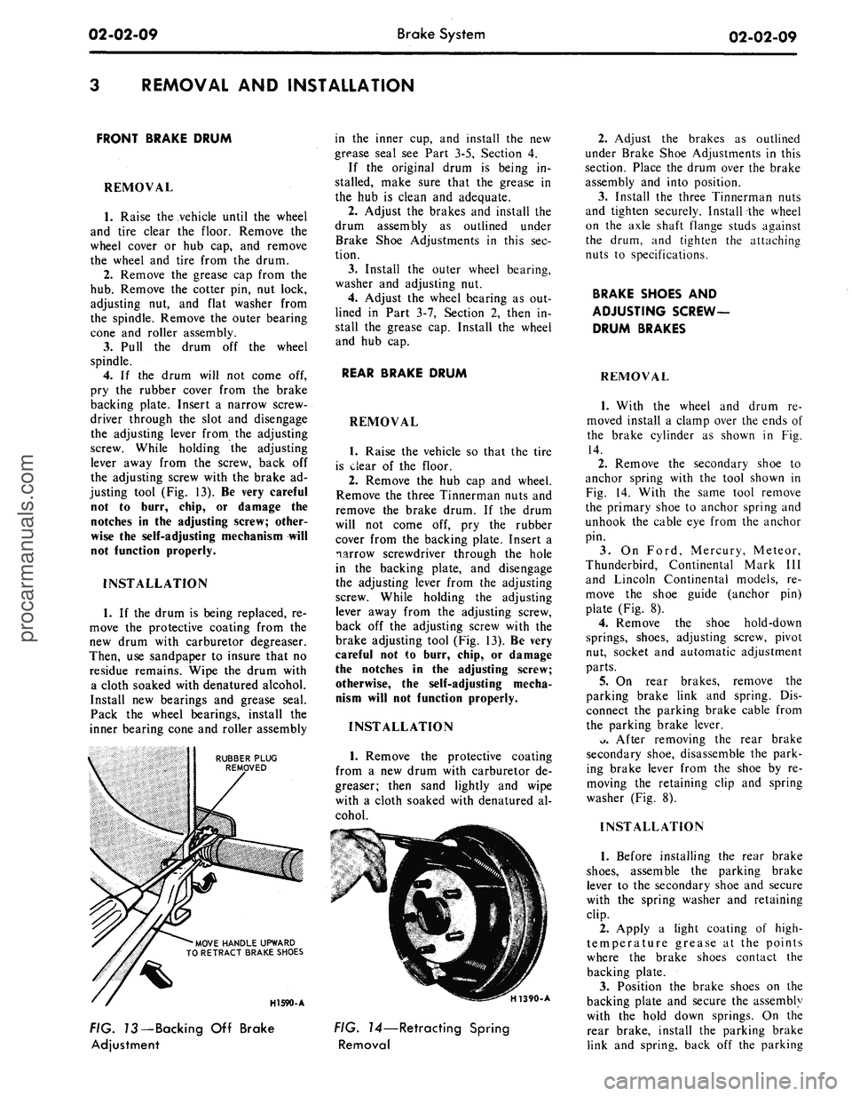
lever away from the screw, back off
the adjusting screw with the brake ad-
justing tool (Fig. 13). Be very careful
not to burr, chip, or damage the
notches in the adjusting screw; other-
wise the self-adjusting mechanism will
not function properly.
INSTALLATION
1.
If the drum is being replaced, re-
move the protective coating from the
new drum with carburetor degreaser.
Then, use sandpaper to insure that no
residue remains. Wipe the drum with
a cloth soaked with denatured alcohol.
Install new bearings and grease seal.
Pack the wheel bearings, install the
inner bearing cone and roller assembly
RUBBER PLUG
REMOVED
'MOVE HANDLE UPWARD
TO RETRACT BRAKE SHOES
in the inner cup, and install the new
grease seal see Part 3-5, Section 4.
If the original drum is being in-
stalled, make sure that the grease in
the hub is clean and adequate.
2.
Adjust the brakes and install the
drum assembly as outlined under
Brake Shoe Adjustments in this sec-
tion.
3.
Install the outer wheel bearing,
washer and adjusting nut.
4.
Adjust the wheel bearing as out-
lined in Part 3-7, Section 2, then in-
stall the grease cap. Install the wheel
and hub cap.
REAR BRAKE DRUM
REMOVAL
1.
Raise the vehicle so that the tire
is clear of the floor.
2.
Remove the hub cap and wheel.
Remove the three Tinnerman nuts and
remove the brake drum. If the drum
will not come off, pry the rubber
cover from the backing plate. Insert a
narrow screwdriver through the hole
in the backing plate, and disengage
the adjusting lever from the adjusting
screw. While holding the adjusting
lever away from the adjusting screw,
back off the adjusting screw with the
brake adjusting tool (Fig. 13). Be very
careful not to burr, chip, or damage
the notches in the adjusting screw;
otherwise, the self-adjusting mecha-
nism will not function properly.
INSTALLATION
1.
Remove the protective coating
from a new drum with carburetor de-
greaser; then sand lightly and wipe
with a cloth soaked with denatured al-
cohol.
HI 590-A
H1390-A
FIG. 73—Backing Off Brake
Adjustment
FIG. 14—Retracting Spring
Removal
2.
Adjust the brakes as outlined
under Brake Shoe Adjustments in this
section. Place the drum over the brake
assembly and into position.
3.
Install the three Tinnerman nuts
and tighten securely. Install the wheel
on the axle shaft flange studs against
the drum, and tighten the attaching
nuts to specifications.
BRAKE SHOES AND
ADJUSTING SCREW-
DRUM BRAKES
REMOVAL
1.
With the wheel and drum re-
moved install a clamp over the ends of
the brake cylinder as shown in Fig.
14.
2.
Remove the secondary shoe to
anchor spring with the tool shown in
Fig. 14. With the same tool remove
the primary shoe to anchor spring and
unhook the cable eye from the anchor
pin.
3.
On Ford, Mercury, Meteor,
Thunderbird, Continental Mark III
and Lincoln Continental models, re-
move the shoe guide (anchor pin)
plate (Fig. 8).
4.
Remove the shoe hold-down
springs, shoes, adjusting screw, pivot
nut, socket and automatic adjustment
parts.
5.
On rear brakes, remove the
parking brake link and spring. Dis-
connect the parking brake cable from
the parking brake lever.
*>.
After removing the rear brake
secondary shoe, disassemble the park-
ing brake lever from the shoe by re-
moving the retaining clip and spring
washer (Fig. 8).
INSTALLATION
1.
Before installing the rear brake
shoes,
assemble the parking brake
lever to the secondary shoe and secure
with the spring washer and retaining
clip.
2.
Apply a light coating of high-
temperature grease at the points
where the brake shoes contact the
backing plate.
3.
Position the brake shoes on the
backing plate and secure the assembly
with the hold down springs. On the
rear brake, install the parking brake
link and spring, back off the parkingprocarmanuals.com
Page 29 of 413
02-02-10
Brake System
02-02-10
brake adjustment then connect the
parking brake cable to the parking
brake lever (Fig. 8).
4.
Install the shoe guide (anchor
pin) plate on the anchor pin when so
equipped.
5.
Place the cable eye over the an-
chor pin with the crimped side toward
the backing plate.
6. Install the primary shoe to an-
chor spring (Fig. 15).
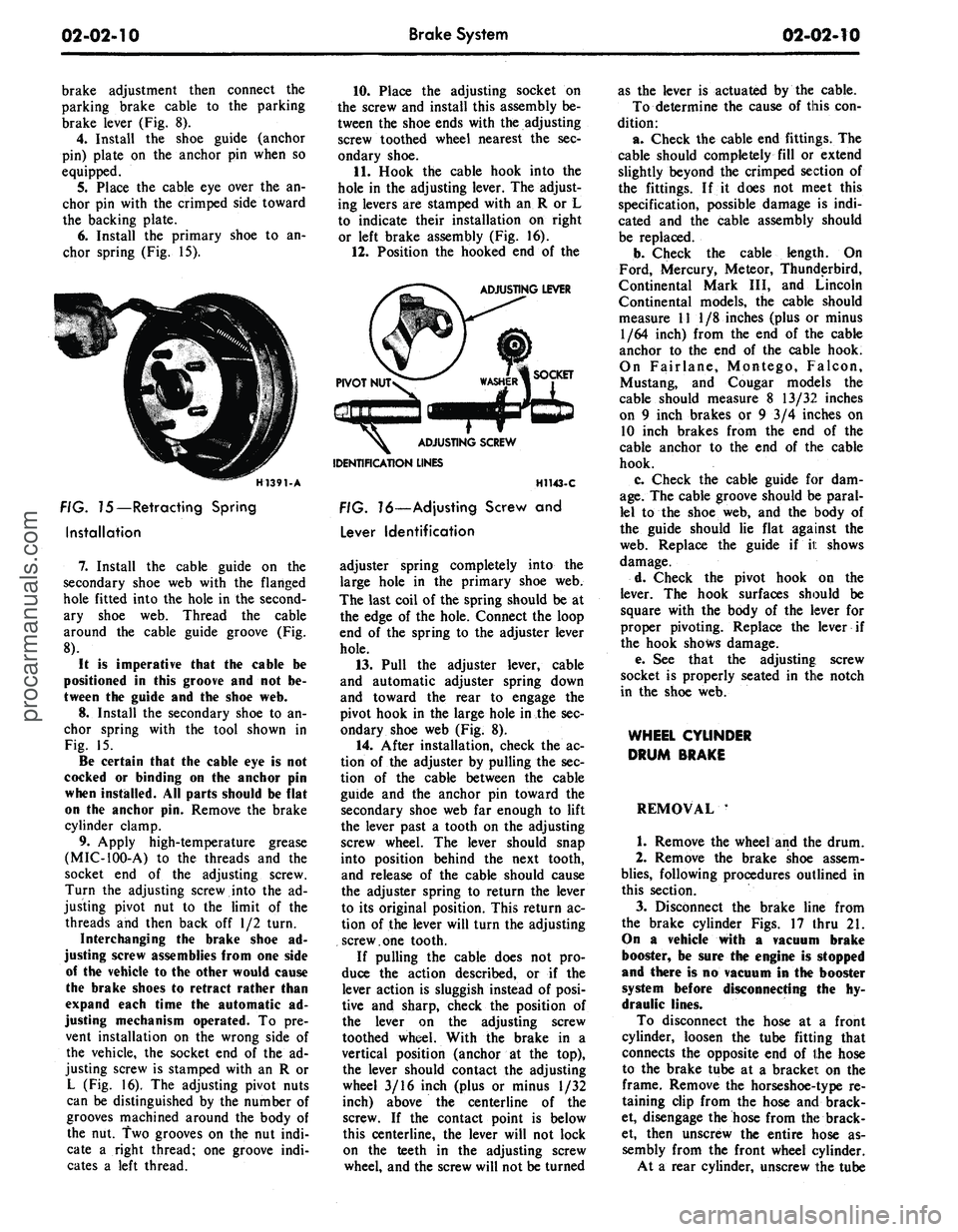
H1391-A
FIG. 75—Retracting Spring
Installation
7.
Install the cable guide on the
secondary shoe web with the flanged
hole fitted into the hole in the second-
ary shoe web. Thread the cable
around the cable guide groove (Fig.
8).
It
is
imperative that
the
cable
be
positioned
in
this groove
and not be-
tween
the
guide
and the
shoe
web.
8.
Install the secondary shoe to an-
chor spring with the tool shown in
Fig. 15.
Be certain that
the
cable
eye is not
cocked
or
binding
on the
anchor
pin
when installed.
All
parts should
be
flat
on
the
anchor
pin.
Remove
the
brake
cylinder clamp.
9. Apply high-temperature grease
(MIC-100-A) to the threads and the
socket end of the adjusting screw.
Turn the adjusting screw into the ad-
justing pivot nut to the limit of the
threads and then back off 1/2 turn.
Interchanging
the
brake shoe
ad-
justing screw assemblies from
one
side
of
the
vehicle
to the
other would cause
the brake shoes
to
retract rather than
expand each time
the
automatic
ad-
justing mechanism operated.
To pre-
vent installation on the wrong side of
the vehicle, the socket end of the ad-
justing screw is stamped with an R or
L (Fig. 16). The adjusting pivot nuts
can be distinguished by the number of
grooves machined around the body of
the nut. Two grooves on the nut indi-
cate a right thread; one groove indi-
cates a left thread.
10.
Place the adjusting socket on
the screw and install this assembly be-
tween the shoe ends with the adjusting
screw toothed wheel nearest the sec-
ondary shoe.
11.
Hook the cable hook into the
hole in the adjusting lever. The adjust-
ing levers are stamped with an R or L
to indicate their installation on right
or left brake assembly (Fig. 16).
12.
Position the hooked end of the
ADJUSTING LEVER
IDENTIFICATION LINES
H1143-C
FIG. 16—Adjusting Screw
and
Lever Identification
adjuster spring completely into the
large hole in the primary shoe web.
The last coil of the spring should be at
the edge of the hole. Connect the loop
end of the spring to the adjuster lever
hole.
13.
Pull the adjuster lever, cable
and automatic adjuster spring down
and toward the rear to engage the
pivot hook in the large hole in the sec-
ondary shoe web (Fig. 8).
14.
After installation, check the ac-
tion of the adjuster by pulling the sec-
tion of the cable between the cable
guide and the anchor pin toward the
secondary shoe web far enough to lift
the lever past a tooth on the adjusting
screw wheel. The lever should snap
into position behind the next tooth,
and release of the cable should cause
the adjuster spring to return the lever
to its original position. This return ac-
tion of the lever will turn the adjusting
screw.one tooth.
If pulling the cable does not pro-
duce the action described, or if the
lever action is sluggish instead of posi-
tive and sharp, check the position of
the lever on the adjusting screw
toothed wheel. With the brake in a
vertical position (anchor at the top),
the lever should contact the adjusting
wheel 3/16 inch (plus or minus 1/32
inch) above the centerline of the
screw. If the contact point is below
this centerline, the lever will not lock
on the teeth in the adjusting screw
wheel, and the screw will not be turned
as the lever is actuated by the cable.
To determine the cause of this con-
dition:
a. Check the cable end fittings. The
cable should completely fill or extend
slightly beyond the crimped section of
the fittings. If it does not meet this
specification, possible damage is indi-
cated and the cable assembly should
be replaced.
b.
Check the cable length. On
Ford, Mercury, Meteor, Thunderbird,
Continental Mark III, and Lincoln
Continental models, the cable should
measure 11 1/8 inches (plus or minus
1/64 inch) from the end of the cable
anchor to the end of the cable hook.
On Fairlane, Montego, Falcon,
Mustang, and Cougar models the
cable should measure 8 13/32 inches
on 9 inch brakes or 9 3/4 inches on
10 inch brakes from the end of the
cable anchor to the end of the cable
hook.
c. Check the cable guide for dam-
age.
The cable groove should be paral-
lel to the shoe web, and the body of
the guide should lie flat against the
web.
Replace the guide if it shows
damage.
d. Check the pivot hook on the
lever. The hook surfaces should be
square with the body of the lever for
proper pivoting. Replace the lever if
the hook shows damage.
e. See that the adjusting; screw
socket is properly seated in the notch
in the shoe web.
WHEEL CYLINDER
DRUM BRAKE
REMOVAL '
1.
Remove the wheel and the drum.
2.
Remove the brake shoe assem-
blies,
following procedures outlined in
this section.
3.
Disconnect the brake line from
the brake cylinder Figs. 17 thru 21.
On
a
vehicle with
a
vacuum brake
booster,
be
sure
the
engine
is
stopped
and there
is no
vacuum
in the
booster
system before disconnecting
the hy-
draulic lines.
To disconnect the hose at a front
cylinder, loosen the tube fitting that
connects the opposite end of the hose
to the brake tube at a bracket on the
frame. Remove the horseshoe-type re-
taining clip from the hose and brack-
et, disengage the hose from the brack-
et, then unscrew the entire hose as-
sembly from the front wheel cylinder.
At a rear cylinder, unscrew the tubeprocarmanuals.com
Page 40 of 413
02-02-21
Brake System
02-02-21
INSTALLATION
CLUTCH ASSIST
SPRING
MASTER CYLINDER
2140
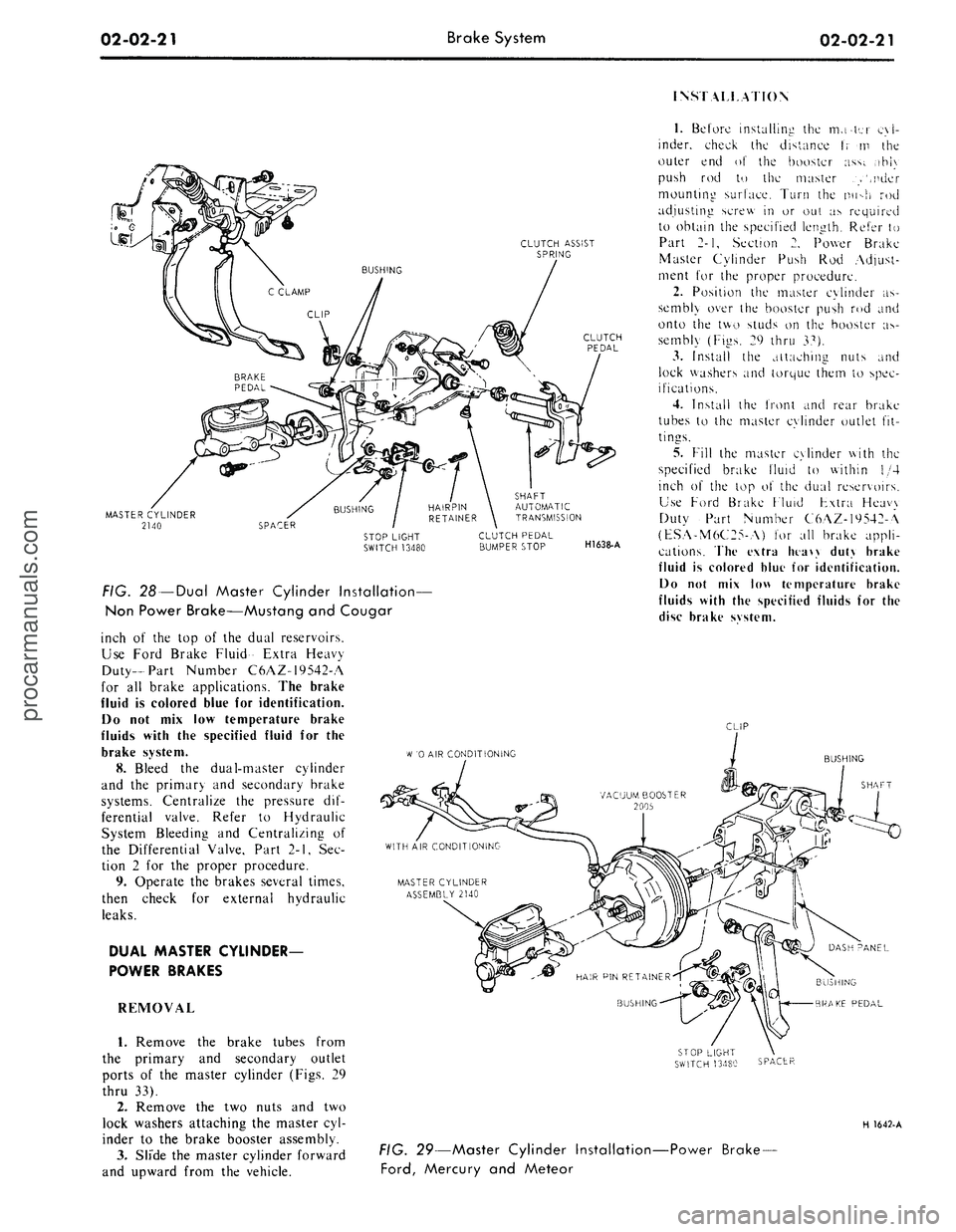
FIG. 28 —Dual Master Cylinder Installation—
Non Power Brake—Mustang and Cougar
inch of the top of the dual reservoirs.
Use Ford Brake Fluid- Extra Heavy
Duty-Part Number C6AZ-19542-A
for all brake applications. The brake
fluid is colored blue for identification.
Do not mix low temperature brake
fluids with the specified fluid for the
brake system.
8. Bleed the dual-master cylinder
and the primary and secondary brake
systems. Centralize the pressure dif-
ferential valve. Refer to Hydraulic
System Bleeding and Centralizing of
the Differential Valve, Part 2-1, Sec-
tion 2 for the proper procedure.
9. Operate the brakes several times,
then check for external hydraulic
leaks.
DUAL MASTER CYLINDER-
POWER BRAKES
REMOVAL
1.
Remove the brake tubes from
the primary and secondary outlet
ports of the master cylinder (Figs. 29
thru 33).
2.
Remove the two nuts and two
lock washers attaching the master cyl-
inder to the brake booster assembly.
3.
Slide the master cylinder forward
and upward from the vehicle.
SHAFT
AUTOMATIC
TRANSMISSION
CLUTCH PEDAL
BUMPER STOP
H1638-A
1.
Before installing the mater cyl-
inder, check the distance t; m the
outer end of the booster ass;. ,ihi\
push rod to the master .>',nder
mounting surface. Turn the nu->h rod
adjusting screw in or out as required
to obtain the specified length. Refer to
Part 2-1, Section 2. Power Brake
Master Cylinder Push Rod Adjust-
ment for the proper procedure.
2.
Position the master cylinder as-
sembly over the booster push rod and
onto the two studs on the booster as-
sembly (Figs. 29 thru 37).
3.
Install the attaching nuts and
lock washers and torque them to spec-
ifications.
4.
Install the front and rear brake
tubes to the master cylinder outlet fit-
tings.
5.
Fill the master cylinder with the
specified brake fluid to within 1/4
inch of the top o\ the dual reservoirs.
Use Ford Brake Fluid Fxtra Heavy
Duty Part Number C6AZ-19542-A
(ESA-M6C25-A) for all brake appli-
cations. The extra htaw duty brake
fluid is colored blue for identification.
Do not mix low temperature brake
fluids with the specified fluids for the
disc brake svstem.
CLIP
W
'0 AIR CONDITIONING
BUSHING
SHAFT
BUSHING
BRAKE PEDAL
SPACER
H 1642-A
FIG. 29—Master Cylinder Installation-
Ford,
Mercury and Meteor
-Power Brake-procarmanuals.com
Page 41 of 413
02-02-22
Brake System
02-02-22
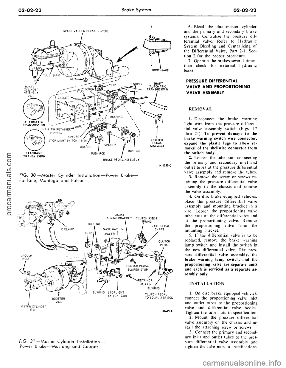
BRAKE VACUUM BOOSTER -2005
AUTOMATIC I
TRANSMISSION
HAIR PIN RETAINER
330699-S2
SPACER
STOP LIGHT SWITCH-13480
STANDARD
TRANSMISSION
BUSHING
BUSHING
PUSH ROD
BRAKE PEDAL ASSEMBLY
CLUTCH
PEDAL
ASSEMBLY
H 1557-C
FIG. 30—Master Cylinder Installation—Power Brake-
Fairlane, Montego and Falcon
ASSIST
SPRING BRACKET CLUTCH ASSIST
\ SPRING
BRAKE PEDAL
SHAFT
CLUTCH
PEDAL
CLUTCH PEDAL
TO EQUALIZER ROD
HI643-
A
FIG. 31—Master Cylinder Installation-
Power Brake—Mustang and Cougar
6. Bleed the dual-master cylinder
and the primary and secondary brake
systems. Centralize the pressure dif-
ferential valve. Refer to H>draulic
System Bleeding and Centralizing of
the Differential Valve, Part 2-1, Sec-
tion 2 for the proper procedure.
7.
Operate the brakes several times,
then check for external hydraulic
leaks.
PRESSURE DIFFERENTIAL
VALVE AND PROPORTIONING
VALVE ASSEMBLY
REMOVAL
1.
Disconnect the brake warning
light wire from the pressure differen-
tial valve assembly switch (Figs. 17
thru 21). To prevent damage to the
brake warning switch wire connector,
expand the plastic lugs to allow re-
moval of the shellwire connector from
the switch body.
2.
Loosen the tube nuts connecting
the primary and secondary inlet and
outlet tubes at the pressure differential
valve assembly and remove the tubes.
3.
Remove the screw or screws re-
taining the pressure differential valve
assembly to the chassis and remove
the valve assembly.
4.
On disc brake equipped vehicles,
place the pressure differential valve
assembly and mounting bracket in a
vise.
Loosen the proportioning valve
tube nuts at the differential valve and
at the proportioning valve. Remove
the proportioning valve from the
mounting bracket.
5.
If the differential valve is to be
replaced, remove the brake warning
lamp switch and install the switch in
the new differential valve. The pres-
sure differential valve assembly, the
brake warning lamp switch, and the
proportioning valve are separate units
and each is serviced as a separate as-
sembly only.
INSTALLATION
1.
On disc brake equipped vehicles,
connect the proportioning valve inlet
and outlet tubes to the proportioning
valve and differential valve bodies.
Tighten the tube nuts to specification.
2.
Mount the pressure differential
valve assembly on the chassis and in-
stall the attaching screw or screws.
3.
Connect the primary and second-
ary inlet and outlet tubes to the pres-
sure differential valve assembly and
tighten the tube nuts to specifications.procarmanuals.com
Page 45 of 413
02-02-26
Brake System
02-02-26
14.
Remove the clutch pedal assist
spring.
15.
On non-power brakes, remove
the retainer clip from the clutch and
brake pedal shaft, then remove the
clutch pedal and shaft assembly, the
brake pedal assembly, and the bush-
ings from the pedal support bracket.
On power brakes, remove the retainer
nut from the brake pedal shaft then
remove the pedal shaft, the brake
pedal assembly and the bushings from
the pedal support bracket.
Installation
1. Apply a coating of SAE 10 en-
gine oil to the bushings and locate all
bushings in their proper places on the
clutch and brake pedal assemblies.
2.
On non-power brakes, position
the brake pedal to the pedal support
bracket, then install the clutch pedal
and shaft assembly through the sup-
port bracket and brake pedal assem-
bly. On power brakes position the
brake pedal to the pedal support
bracket, then install the pedal shaft
and nut.
3.
Install the clutch pedal assist
spring and pivot the clutch pedal
against its bumper stop. Secure the
pedal to the stop with a small C-
clamp as shown in Figs. 28 and 31.
4.
Position the pedal support
bracket assembly to the dash panel,
and to the steering column retainer
studs.
5.
Align the pedal support bracket
holes with the holes in the dash panel
and install the two attaching sheet
metal screws. On power brakes install
the nuts on the brake booster studs.
6. Install the two cap screws at-
taching the pedal support bracket to
the upper cowl bracket.
7. Install the cap screw attaching
the pedal support bracket to the top
inner cowl bracket (Figs. 28 and 31).
8. Install the inner nylon washer,
the master cylinder push rod, and the
bushing on the brake pedal pin. Posi-
tion the stop light switch so that it
straddles the push rod with the switch
slot on the pedal pin and the switch
outer hole just clearing the pin. Slide
the switch completely onto the pin,
and install the outer nylon washer as
shown in Figs. 28 and 31. Secure
these parts to the pin with the
self-
locking retainer.
9. Connect the stop light switch
wires to the connector.
10.
Connect the clutch pedal-
to-equalizer rod to the clutch pedal
assembly with the bushing and the
spring clip retainer. Apply SAE 10
engine oil to the bushing. Remove the
C-clamp from the clutch pedal.
11.
Working from the engine side
of the dash panel, on non-power
brakes, install the two cap screws at-
taching the pedal support bracket to
the dash panel. Then install the two
screws attaching the master cylinder
to the dash panel. On power brakes
install the cap screws retaining the
brake booster to the dash panel.
12.
Install the steering column.
Refer to Part 3-4, Section 2 for pro-
cedure.
13.
Adjust the clutch pedal free
play (Group 5) to specification, if re-
quired.
14.
Check the Brake Pedal Free
Height and Travel Measurements
(Part 2-1, Section 1).
15.
Connect the ground cable to the
battery.
FAIRLANE, MONTEGO,
FALCON, MUSTANG
AND COUGAR-
AUTOMATIC TRANSMISSION
Removal
1. Disconnect the stop light switch
wires at the connector.
2.
Remove the self-locking pin and
slide the stop light switch off the
brake pedal pin just far enough for
the switch outer hole to clear the pin.
Then lower the switch away from the
pin. Slide the master cylinder or
booster push rod and the nylon wash-
ers and bushing off from the brake
pedal pin (Figs. 27, 28, 30 and 31).
3.
On all vehicles except Mustang
and Cougar with power brakes, re-
move the self-locking pin and washer
from the brake pedal shaft, then re-
move the shaft, the brake pedal as-
sembly and the bushings from the
pedal support bracket. On Mustang
and Cougar vehicles with power
brakes, remove the locknut and bolt
from the pedal. Remove the pedal as-
sembly from the support bracket (Fig.
3).
Installation
1. Apply a coating of SAE 10 en-
gine oil to the bushings and locate all
the bushings in their proper places on
the pedal assembly and pedal support
bracket (Figs. 27, 28, 30 and 31).
2.
Position the brake pedal assem-
bly to the support bracket, then install
the pedal shaft or bolt through the
support bracket and brake pedal as-
sembly. Install the retainer or locknut.
3.
Install the inner nylon washer,
the master cylinder or booster push
rod, and the bushing on the brake
pedal pin. Position the switch so that
it straddles the push rod with the
switch slot on the pedal pin, and the
switch outer hole just clearing the pin.
Slide the switch completely onto the
pin, and install the outer nylon washer
as shown in Figs. 27, 28, 30 and 31.
Secure these parts to the pin with the
self-locking pin.
4.
Connect the stop light switch
wires to the connector, and install the
wires in the retaining clip.
Check the Brake Pedal Free Height
and Travel Measurements, Part 2,
Section 1.
THUNDERBIRD
AND
CONTINENTAL MARK
III
Removal
1.
Loosen the booster mounting
nuts.
2.
Disconnect the stop light switch
wires at the connector.
3.
Remove the hairpin retainer.
Slide the stop light switch off from
the brake pedal pin just far enough
for
the
switch outer hole
to
clear
the
pin,
and then lift the switch straight
upward from the pin. Slide the master
cylinder push rod and the nylon wash-
ers and bushing off from the brake
pedal pin (Fig. 32).
4.
Remove the pivot bolt and nut
that holds the pedal to the pedal sup-
port bracket. Remove the brake pedal
assembly from the pedal support
bracket, and remove the bushings.
Installation
1. Apply a coating of SAE 10 en-
gine oil to the bushings and locate all
the bushings in their proper places on
the pedal assembly (Fig. 32).
2.
Install the brake pedal assembly
and bushings to the support bracket,
and then install the pivot bolt through
the support bracket and brake pedal
assembly. Install the pivot bolt nut
and torque to specifications.
3.
Install the inner nylon washer,
the master cylinder push rod, and the
bushing on the brake pedal pin. Posi-
tion the switch so that it straddles the
push rod with the switch slot on the
pedal pin and the switch outer hole
just clearing the pin. Slide the switch
completely onto the pin, install the
outer nylon washer as shown in Fig.
32.
Secure these parts to the pin with
the hairpin retainer.procarmanuals.com