checking oil FORD MUSTANG 1969 Volume One Chassis
[x] Cancel search | Manufacturer: FORD, Model Year: 1969, Model line: MUSTANG, Model: FORD MUSTANG 1969Pages: 413, PDF Size: 75.81 MB
Page 151 of 413
03-08-07
Ford Design Integral Power Steering Gear
03-08-07
Press Ram
Tool-
T65P.3524-A1
G1362-A
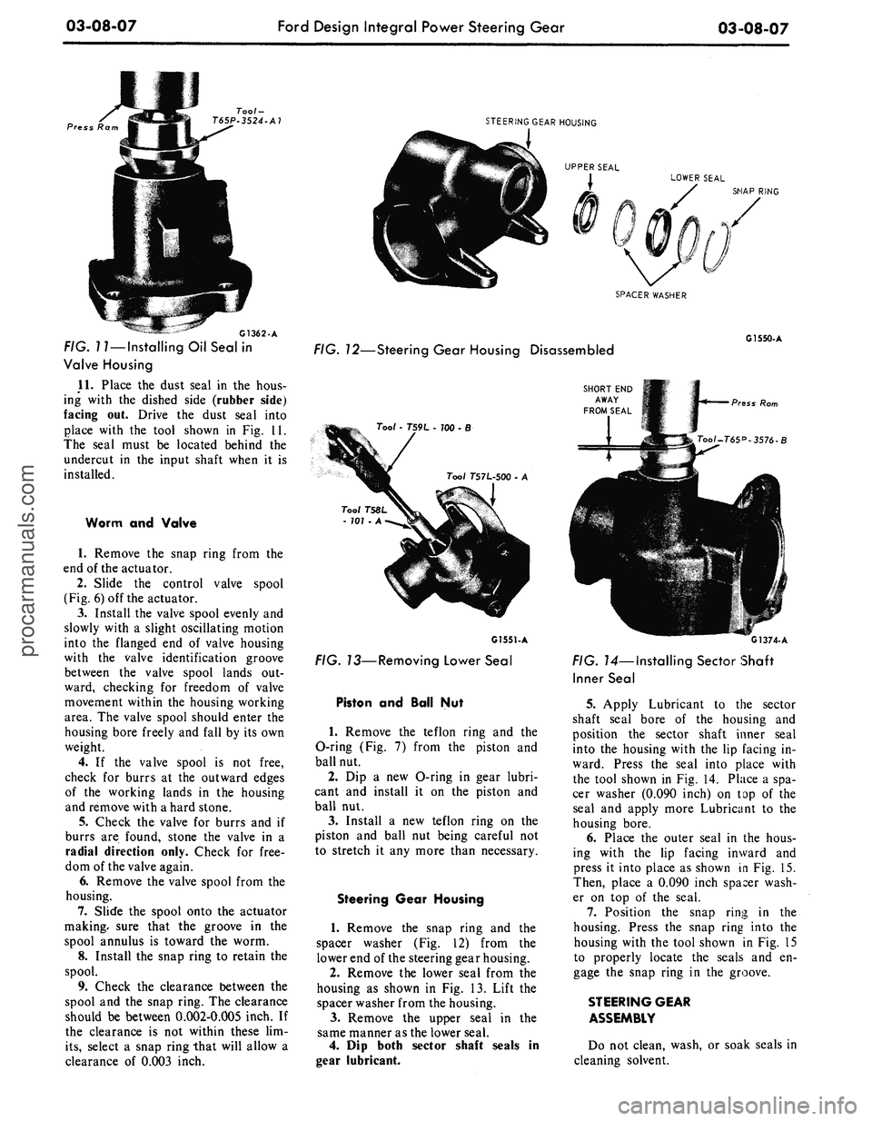
FIG.
17—Installing
Oil Seal in
Valve Housing
11.
Place the dust seal in the hous-
ing with the dished side (rubber side)
facing out. Drive the dust seal into
place with the tool shown in Fig. 11.
the seal must be located behind the
undercut in the input shaft when it is
installed.
Worm and Valve
1.
Remove the snap ring from the
end of the actuator.
2.
Slide the control valve spool
(Fig. 6) off the actuator.
3.
Install the valve spool evenly and
slowly with a slight oscillating motion
into the flanged end of valve housing
with the Valve identification groove
between the valve spool lands out-
ward, checking for freedom of valve
movement within the housing working
area. The valve spool should enter the
housing bore freely and fall by its own
weight.
4.
If the valve spool is not free,
check for burrs at the outward edges
of the working lands in the housing
and remove with a hard stone.
5.
Check the valve for burrs and if
burrs are found, stone the valve in a
radial direction only. Check for free-
dom of the valve again.
6. Remove the valve spool from the
housing.
7.
Slide the spool onto the actuator
making, sure that the groove in the
spool annulus is toward the worm.
8. Install the snap ring to retain the
spool.
9. Check the clearance between the
spool and the snap ring. The clearance
should be between 0.002-0.005 inch. If
the clearance is not within these lim-
its,
select a snap ring that will allow a
clearance of 0.003 inch.
STEERING GEAR HOUSING
J
UPPER SEAL
I LOWER SEAL
SNAP RING
SPACER WASHER
FIG. 12—Steering Gear Housing Disassembled
Tool - T59L - 100-B
Tool T57L-500 - A
G1551-A
FIG. 13—Removing Lower Seal
Piston and Ball Nut
1.
Remove the teflon ring and the
O-ring (Fig. 7) from the piston and
ball nut.
2.
Dip a new O-ring in gear lubri-
cant and install it on the piston and
ball nut.
3.
Install a new teflon ring on the
piston and ball nut being careful not
to stretch it any more than necessary.
Steering Gear Housing
1.
Remove the snap ring and the
spacer washer (Fig. 12) from the
lower end of the steering gear housing.
2.
Remove the lower seal from the
housing as shown in Fig. 13. Lift the
spacer washer from the housing.
3.
Remove the upper seal in the
same manner as the lower seal.
4.
Dip both sector shaft seals in
gear lubricant.
SHORT END
AWAY
FROM SEAL
G1550-A
Press Rom
G1374-A
FIG. 14—Installing Sector Shaft
Inner Seal
5. Apply Lubricant to the sector
shaft seal bore of the housing and
position the sector shaft inner seal
into the housing with the lip facing in-
ward. Press the seal into place with
the tool shown in Fig. 14. Place a spa-
cer washer (0.090 inch) on top of the
seal and apply more Lubricant to the
housing bore.
6. Place the outer seal in the hous-
ing with the lip facing inward and
press it into place as shown in Fig. 15.
Then, place a 0.090 inch spacer wash-
er on top of the seal.
7.
Position the snap ring in the
housing. Press the snap ring into the
housing with the tool shown in Fig. 15
to properly locate the seals and en-
gage the snap ring in the groove.
STEERING GEAR
ASSEMBLY
Do not clean, wash, or soak seals in
cleaning solvent.procarmanuals.com
Page 187 of 413
03-13-08
Specifications
03-13-08
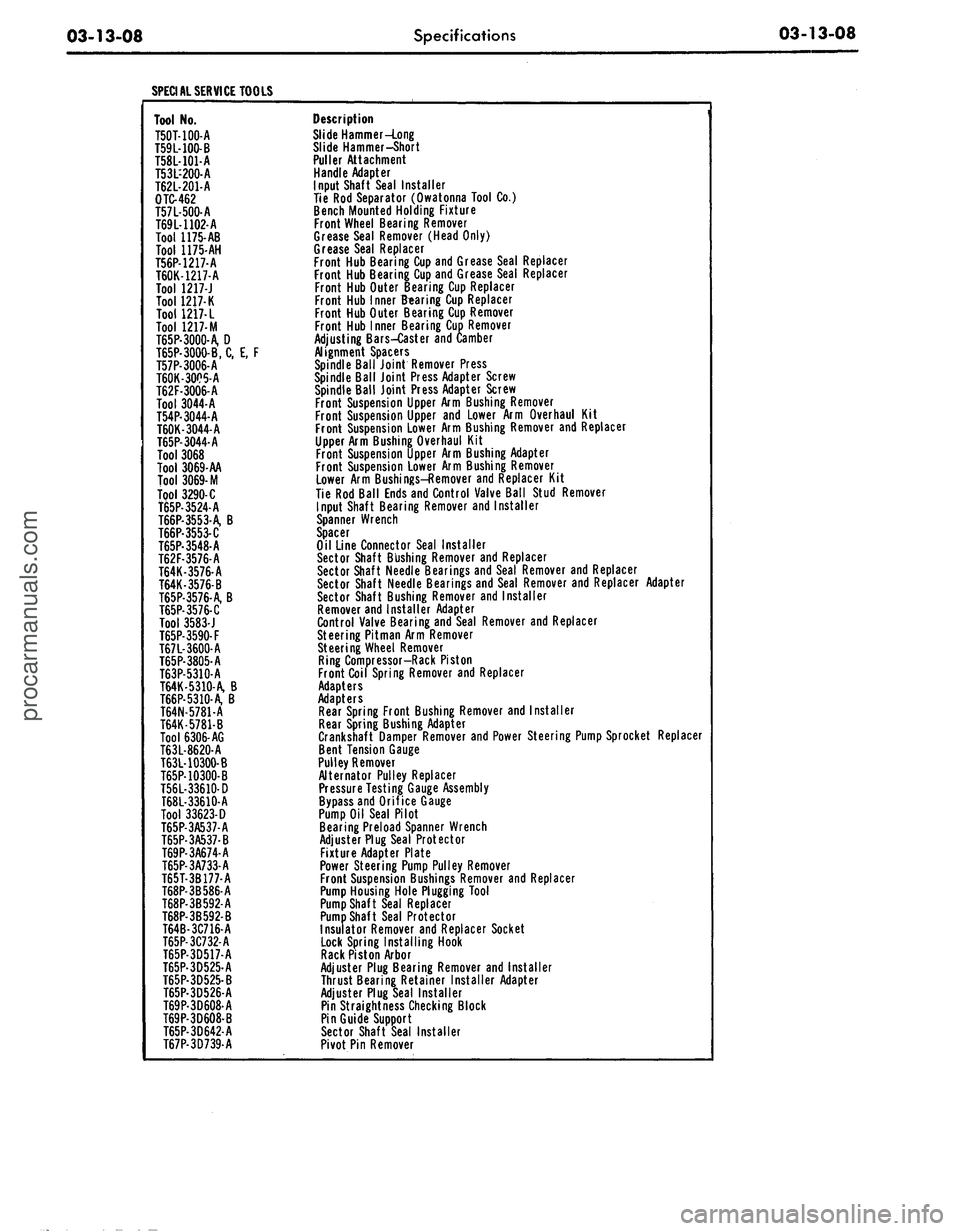
SPECIAL SERVICE TOOLS
Tool No.
T50T-100-A
T59L-100-B
T58L-101-A
T53L-200-A
T62L-201-A
OTC-462
T57L-500-A
T69L-1102-A
Tool 1175-AB
Tool 1175-AH
T56P-1217-A
T60K-1217-A
Tool 1217-J
Tool 1217-K
Tool
1217- L
Tool 1217-M
T65P-3000-A, D
T65P-3000-B, C, E, F
T57P-3006-A
T60K-3005-A
T62F-3006-A
Tool 3044-A
T54P-3044-A
T60K-3044-A
T65P-3044-A
Tool 3068
Tool 3069-AA
Tool
3069-
M
Tool 3290-C
T65P-3524-A
T66P-3553-A, B
T66P-3553-C
T65P-3548-A
T62F-3576-A
T64K-3576-A
T64K-3576-B
T65P-3576-A, B
T65P-3576-C
Tool 3583-J
T65P-3590-F
T67L-3600-A
T65P-3805-A
T63P-5310-A
T64K-5310-A, B
T66P-5310-A, B
T64N-5781-A
T64K-5781-B
Tool 6306-AG
T63L-8620-A
T63L-10300-B
T65P-10300-B
T56L-33610-D
T68L-33610-A
Tool 33623-D
T65P-3A537-A
T65P-3A537-B
T69P-3A674-A
T65P-3A733-A
T65T-3B177-A
T68P-3B586-A
T68P-3B592-A
T68P-3B592-B
T64B-3C716-A
T65P-3C732-A
T65P-3D517-A
T65P-3D525-A
T65P-3D525-B
T65P-3D526-A
T69P-3D608-A
T69P-3D608-B
T65P-3D642-A
T67P-3D739-A
Description
Slide Hammer-Long
Slide Hammer-Short
Puller Attachment
Handle Adapter
Input Shaft Seal Installer
Tie Rod Separator (Owatonna Tool Co.)
Bench Mounted Holding Fixture
Front Wheel Bearing Remover
Grease Seal Remover (Head Only)
Grease Seal Replacer
Front Hub Bearing Cup and Grease Seal Replacer
Front Hub Bearing Cup and Grease Seal Replacer
Front Hub Outer Bearing Cup Replacer
Front Hub Inner Bearing Cup Replacer
Front Hub Outer Bearing Cup Remover
Front Hub Inner Bearing Cup Remover
Adjusting Bars-Caster and Camber
Alignment Spacers
Spindle Ball Joint Remover Press
Spindle Ball Joint Press Adapter Screw
Spindle Ball Joint Press Adapter Screw
Front Suspension Upper Arm Bushing Remover
Front Suspension Upper and Lower Arm Overhaul Kit
Front Suspension Lower Arm Bushing Remover and Replacer
Upper Arm Bushing Overhaul Kit
Front Suspension Upper Arm Bushing Adapter
Front Suspension Lower Arm Bushing Remover
Lower Arm Bushings-Remover and Replacer Kit
Tie Rod Ball Ends and Control Valve Ball Stud Remover
Input Shaft Bearing Remover and Installer
Spanner Wrench
Spacer
Oil Line Connector Seal Installer
Sector Shaft Bushing Remover and Replacer
Sector Shaft Needle Bearings and Seal Remover and Replacer
Sector Shaft Needle Bearings and Seal Remover and Replacer Adapter
Sector Shaft Bushing Remover and Installer
Remover and Installer Adapter
Control Valve Bearing and Seal Remover and Replacer
Steering Pitman Arm Remover
Steering Wheel Remover
Ring Compressor-Rack Piston
Front Coil Spring Remover and Replacer
Adapters
Adapters
Rear Spring Front Bushing Remover and Installer
Rear Spring Bushing Adapter
Crankshaft Damper Remover and Power Steering Pump Sprocket Replacer
Bent Tension Gauge
Pulley Remover
Alternator Pulley Replacer
Pressure Testing Gauge Assembly
Bypass and Orifice Gauge
Pump Oil Seal Pilot
Bearing Preload Spanner Wrench
Adjuster Plug Seal Protector
Fixture Adapter Plate
Power Steering Pump Pulley Remover
Front Suspension Bushings Remover and Replacer
Pump Housing Hole Plugging Tool
Pump Shaft Seal Replacer
Pump Shaft Seal Protector
Insulator Remover and Replacer Socket
Lock Spring Installing Hook
Rack Piston Arbor
Adjuster Plug Bearing Remover and Installer
Thrust Bearing Retainer Installer Adapter
Adjuster Plug Seal Installer
Pin Straightness Checking Block
Pin Guide Support
Sector Shaft Seal Installer
Pivot Pin Removerprocarmanuals.com
Page 194 of 413
04-01-07
General Axle Service
04-01-07
Tool-4201-
C
Tool-6565 USED WITH BRACKET
FROM Too/^*207-C
FLANGE
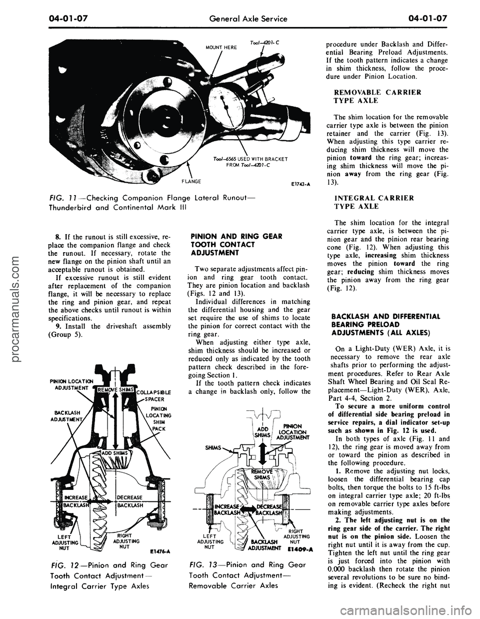
E1743-A
procedure under Backlash and Differ-
ential Bearing Preload Adjustments.
If the tooth pattern indicates a change
in shim thickness, follow the proce-
dure under Pinion Location.
REMOVABLE CARRIER
TYPE AXLE
The shim location for the removable
carrier type axle is between the pinion
retainer and the carrier (Fig. 13).
When adjusting this type carrier re-
ducing shim thickness will move the
pinion toward the ring gear; increas-
ing shim thickness will move the pi-
nion away from the ring gear (Fig.
13).
FIG. 11—Checking Companion Flange Lateral Runout—
Thunderbird and Continental Mark III
INTEGRAL CARRIER
TYPE AXLE
8. If the runout is still excessive, re-
place the companion flange and check
the runout. If necessary, rotate the
new flange on the pinion shaft until an
acceptable runout is obtained.
If excessive runout is still evident
after replacement of the companion
flange, it will be necessary to replace
the ring and pinion gear, and repeat
the above checks until runout is within
specifications.
9. Install the driveshaft assembly
(Group 5).
PINION LOCATION
ADJUSTMENT
BACKLASH
ADJUSTMENT,
LEFT
ADJUSTING
NUT
E1476-A
FIG. 12—Pinion and Ring Gear
Tooth Contact Adjustment
—
Integral Carrier Type Axles
PINION AND RING GEAR
TOOTH CONTACT
ADJUSTMENT
Two separate adjustments affect pin-
ion and ring gear tooth contact.
They are pinion location and backlash
(Figs.
12 and 13).
Individual differences in matching
the differential housing and the gear
set require the use of shims to locate
the pinion for correct contact with the
ring gear.
When adjusting either type axle,
shim thickness should be increased or
reduced only as indicated by the tooth
pattern check described in the fore-
going Section 1.
If the tooth pattern check indicates
a change in backlash only, follow the
PINION
LOCATION
ADJUSTMENT
SHIMS
LEFT
ADJUSTING
NUT
RIGHT
ADJUSTING
BACKLASH NUT
ADJUSTMENT El 409-A
FIG. 13—Pinion and Ring Gear
Tooth Contact Adjustment—
Removable Carrier Axles
The shim location for the integral
carrier type axle, is between the pi-
nion gear and the pinion rear bearing
cone (Fig. 12). When adjusting this
type axle, increasing shim thickness
moves the pinion toward the ring
gear; reducing shim thickness moves
the pinion away from the ring gear
(Fig. 12).
BACKLASH AND DIFFERENTIAL
BEARING PRELOAD
ADJUSTMENTS (ALL AXLES)
On a Light-Duty (WER) Axle, it is
necessary to remove the rear axle
shafts prior to performing the adjust-
ment procedures. Refer to Rear Axle
Shaft Wheel Bearing and Oil Seal Re-
placement—Light-Duty (WER), Axle,
Part 4-4, Section 2.
To secure a more uniform control
of differential side bearing preload in
service repairs, a dial indicator set-up
such as shown in Fig. 12 is used.
In both types of axle (Fig. 11 and
12),
the ring gear is moved away from
or toward the pinion as described in
the following procedure.
1.
Remove the adjusting nut locks,
loosen the differential bearing cap
bolts,
then torque the bolts to 15 ft-lbs
on integral carrier type axle; 20 ft-lbs
on removable carrier type axles before
making adjustments.
2.
The left adjusting nut is on the
ring gear side of the carrier. The right
nut is on the pinion side. Loosen the
right nut until it is away from the cup.
Tighten the left nut until the ring gear
is just forced into the pinion with
0.000 backlash then rotate the pinion
several revolutions to be sure no bind-
ing is evident. (Recheck the right nutprocarmanuals.com
Page 196 of 413
04-01-09
General Axle Service
04-01-09
CLEANING AND INSPECTION
INSPECTION BEFORE
DISASSEMBLY OF CARRIER
(ALL AXLES)
The differential case or carrier
should be inspected before any parts
are removed from it. These inspec-
tions can help to find the cause of the
trouble and to determine the correc-
tions needed.
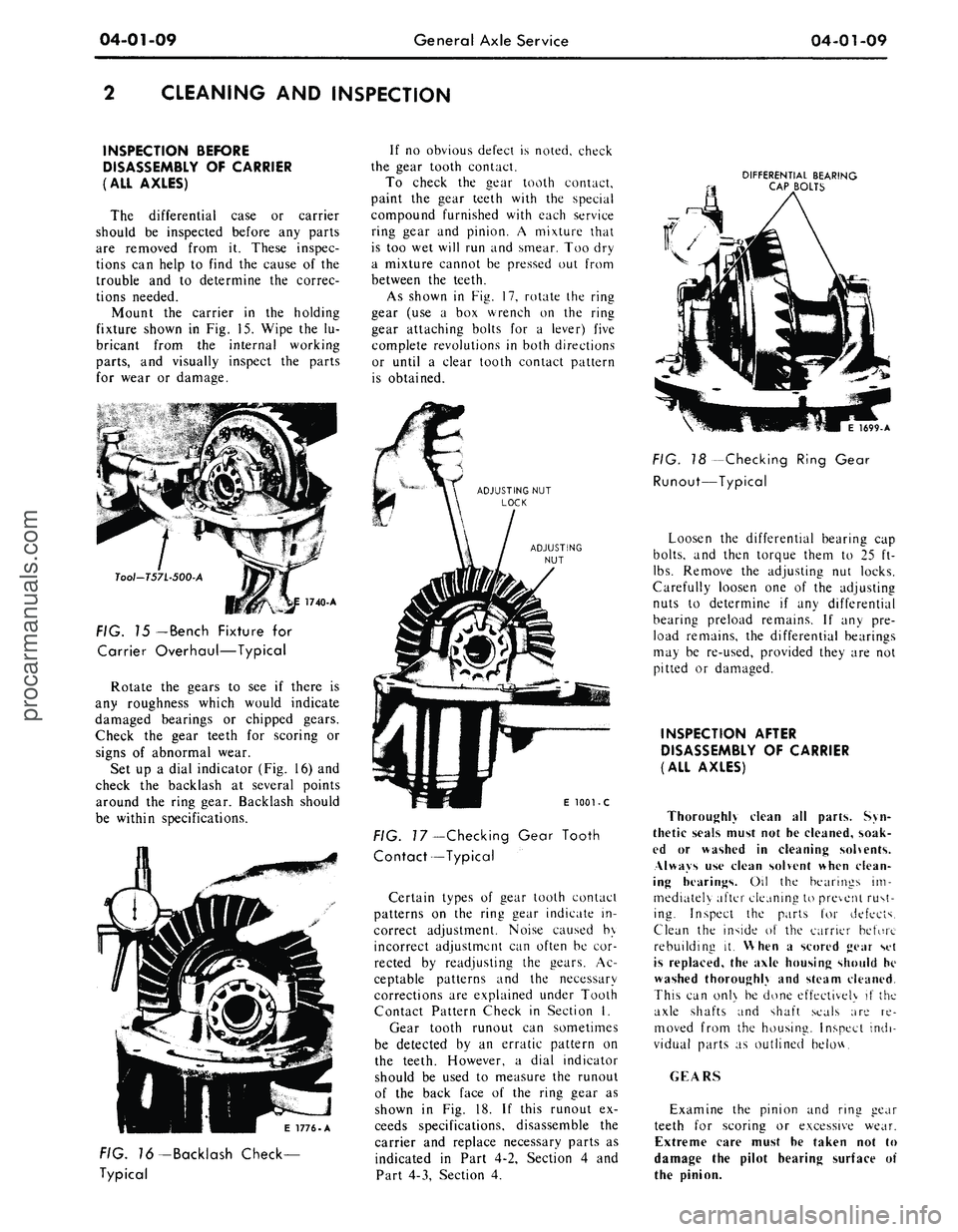
Mount the carrier in the holding
fixture shown in Fig. 15. Wipe the lu-
bricant from the internal working
parts,
and visually inspect the parts
for wear or damage.
Tool-T57L-500-A
FIG. 15
— Bench
Fixture for
Carrier Overhaul—Typical
Rotate the gears to see if there is
any roughness which would indicate
damaged bearings or chipped gears.
Check the gear teeth for scoring or
signs of abnormal wear.
Set up a dial indicator (Fig. 16) and
check the backlash at several points
around the ring gear. Backlash should
be within specifications.
If no obvious defect is noted, check
the gear tooth contact.
To check the gear tooth contact,
paint the gear teeth with the special
compound furnished with each service
ring gear and pinion. A mixture that
is too wet will run and smear. Too dry
a mixture cannot be pressed out from
between the teeth.
As shown in Fig. 17, rotate the ring
gear (use a box wrench on the ring
gear attaching bolts for a lever) five
complete revolutions in both directions
or until a clear tooth contact pattern
is obtained.
DIFFERENTIAL BEARING
CAP BOLTS
E 1776-A
FIG. 76-Backlash Check-
Typical
E
1001 - C
FIG.
7
7—Checking Gear Tooth
Contact—Typical
Certain types of gear tooth contact
patterns on the ring gear indicate in-
correct adjustment. Noise caused by
incorrect adjustment can often be cor-
rected by readjusting the gears. Ac-
ceptable patterns and the necessary
corrections are explained under Tooth
Contact Pattern Check in Section I.
Gear tooth runout can sometimes
be detected by an erratic pattern on
the teeth. However, a dial indicator
should be used to measure the runout
of the back face of the ring gear as
shown in Fig. 18. If this runout ex-
ceeds specifications, disassemble the
carrier and replace necessary parts as
indicated in Part 4-2, Section 4 and
Part 4-3, Section 4.
1699-A
FIG. 18 -Checking Ring Gear
Runout—Typical
Loosen the differential bearing cap
bolts,
and then torque them to 25 ft-
lbs.
Remove the adjusting nut locks.
Carefully loosen one of the adjusting
nuts to determine if any differential
bearing preload remains. If any pre-
load remains, the differential bearings
may be re-used, provided they are not
pitted or damaged.
INSPECTION AFTER
DISASSEMBLY OF CARRIER
(ALL AXLES)
Thoroughly clean all parts. Syn-
thetic seals must not he cleaned, soak-
ed or washed in cleaning solvents.
Always use clean solvent when clean-
ing hearings. Oil the bearings im-
mediately after cleaning to prevent rust-
ing. Inspect the parts for defects.
Clean the inside of the carrier before
rebuilding it. When a scored gear set
is replaced, the axle housing should he
washed thoroughly and steam cleaned.
This can onl\ be done effectively if the
axle shafts and shaft seals are re-
moved from the housing. Inspect indi-
vidual parts as outlined below.
GEARS
Examine the pinion and ring gear
teeth for scoring or excessive wear.
Extreme care must he taken not to
damage the pilot hearing surface of
the pinion.procarmanuals.com
Page 216 of 413
04-02-19
Rear Axle — Removable Carrier Type
04-02-19
POINTER RESTING ON
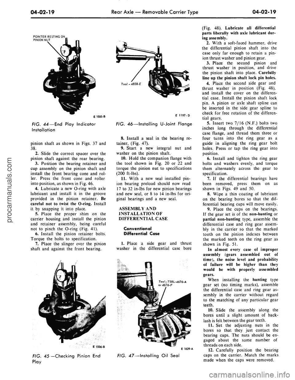
PINION NUT
E 1505-B
FIG.
44
— End Play Indicator
Installation
pinion shaft as shown in Figs. 37 and
38.
2.
Slide the correct spacer over the
pinion shaft against the rear bearing.
3.
Position the bearing retainer and
cup assembly on the pinion shaft and
install the front bearing cone and rol-
ler. Press the front cone and roller
into position, as shown in Fig. 46.
4.
Lubricate a new O-ring with axle
lubricant and install it in the groove
provided in the pinion retainer. Be
careful not to twist the O-ring. Install
it by snapping it into place.
5.
Place the proper shim on the
carrier housing and install the pinion
and retainer assembly, being careful
not to pinch the O-ring (Fig. 41).
6. Install the pinion retainer bolts.
Torque the bolts to specification.
7.
Place the slinger over the pinion
shaft and against the front bearing.
Tool - 4858-
E
E 1197-D
FIG. 46—Installing
U-Joint
Flange
8. Install a seal in the bearing re-
tainer, (Fig. 47).
9. Start a new integral nut and
washer on the pinion shaft.
10.
Hold the companion flange with
the tool shown in Fig. 20 or 22 and
torque the pinion nut to specifications
(200 ft-lbs).
11.
With a new seal installed pin-
ion bearing preload should now read
17 to 32 in-lbs for new pinion bearings
and new seal, or 8 to 14 in-lbs for ori-
ginal bearings and a new seal.
ASSEMBLY AND
INSTALLATION OF
DIFFERENTIAL CASE
Conventional
Differential Case
1.
Place a side gear and thrust
washer in the differential case bore
E 1506-B
E 1629-A
FIG. 45— Checking Pinion End
Play
FIG. 47—Installing Oil Seal
(Fig. 48). Lubricate all differential
parts liberally with axle lubricant dur-
ing assembly.
2.
With a soft-faced hammer, drive
the differential pinion shaft into the
case only far enough to retain a pin-
ion thrust washer and pinion gear.
3.
Place the second pinion and
thrust washer in position, and drive
the pinion shaft into place. Carefully
line up the pinion shaft lock pin holes.
4.
Place the second side gear and
thrust washer in position (Fig. 48),
and install the cover on the differen-
tial case. Install the pinion shaft lock
pin. A pinion or axle shaft spline can
be inserted in the side gear spline to
check for free rotation of the differen-
tial gears.
5.
Insert two 7/16 (N.F.) bolts two
inches long through the differential
case flange, and thread them three or
four turns into the ring gear as a
guide in aligning the ring gear bolt
holes.
Press or tap the ring gear into
position.
6. Install and tighten the ring gear
bolts and washers evenly, and torque
them alternately across the gear to
specification.
7.
If the differential bearings have
been removed, press them on as
shown in Figs. 49 and 50.
8. Wipe a thin coating of lubricant
on the bearing bores so that the dif-
ferential bearing cups will move easily.
9. Place the cups on the bearings.
If the gear set is of the non-hunting or
partial non-hunting type, assemble the
differential case and ring gear assem-
bly in the carrier so that the marked
tooth on the pinion indexes between
the marked teeth on the ring gear as
shown in Fig. 51.
In almost every case of improper
assembly (gears assembled out of
time),
the noise level and probability
of failure will be higher than they
would be with properly assembled
gears.
When installing the hunting type
gear set (no timing marks), assemble
the differential case and ring gear as-
sembly in the carrier without regard
to the matching of any particular gear
teeth.
10.
Slide the assembly along the
bores until a slight amount of back-
lash is felt between the gear teeth.
11.
Set the adjusting nuts in the
bores so that they just contact the
bearing cups. The nuts should be en-
gaged about the same number of
threads on each side.
12.
Carefully position the bearing
caps on the carrier. Match the marks
made when the caps were removed.procarmanuals.com
Page 224 of 413
04-03-04
Rear Axles — Integral Carrier Type
04-03-04
1.
Remove the wheel cover, wheel
and tire from the brake drum.
2.
Remove the Tinnerman nuts that
secure the brake drum to the axle
housing flange, and then remove the
drum from the flange.
3.
Working through the hole pro-
vided in each axle shaft flange, re-
move the nuts that secure the wheel
bearing retainer plate. Then pull the
axle shaft assembly out of the axle
housing (Fig. 2). The brake backing
plate must, not be dislodged. Install
one nut to hold the plate in place after
the axle shaft is removed.
4.
If the rear wheel bearing is to be
replaced, loosen the inner retainer
ring by nicking it deeply with a cold
chisel in several places (Fig. 3). It will
then slide off easily.
5.
Remove the bearing from the
axle shaft with the tool shown in Fig.
4 or 5. If the push-puller operation
shown in Fig. 5 is used, be sure that
the puller arms contact the flat sur-
face of the axle shaft flange rather
than the bolt heads. Also with this
method, be careful not to damage or
burr the oil seal journal as the bearing
breaks loose.
6. Whenever a rear axle shaft is re-
placed the oil seal must be replaced.
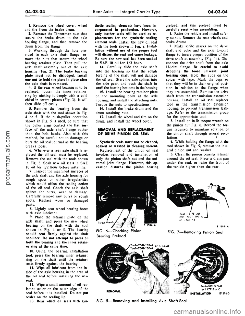
Remove the seal with the tools shown
in Fig. 8. Soak new oil seals in SAE
10 oil for 1/2 hour before installing.
7.
Inspect the machined surfaces of
the axle shaft and the axle housing for
rough spots or other irregularities
which would affect the sealing action
of the oil seal. Check the axle shaft
splines for burrs, wear or damage.
Carefully remove any burrs or rough
spots.
Replace worn or damaged
parts.
8. Lightly coat wheel bearing bores
with axle lubricant.
9. Place the retainer plate on the
axle shaft, and press the new wheel
bearing on the shaft with the tool
shown in Fig. 4 or 5. The bearing
should seat firmly against the shaft
shoulder. Do not attempt to press on
both the bearing and the inner retain-
er ring at the same time.
10.
Using the bearing installation
tool, press the bearing inner retainer
ring on the shaft until the retainer
seats firmly against the bearing.
11.
Wipe all lubricant from the in-
side of the axle housing in the area of
the oil seal before installing the new
seal.
12.
Wipe a small amount of oil res-
istant sealer on the outer edge of the
seal before it is installed. Do not put
sealer on the sealing lip.
13.
Rear wheel oil seals with syn-
thetic sealing elements have been in-
corporated in production. However,
only leather seals will be used as re-
placements for the synthetic sealing
element seals. Install the new oil seal
with the tools shown in Fig. 8. Instal-
lation without use of the proper tool
will distort the seal and cause leakage.
Be sure the new seal has been soaked
in SAE 10 oil for 1/2 hour.
14.
Carefully slide the axle shaft
into the housing so that the rough
forging of the shaft will not damage
the oil seal. Start the axle splines into
the side gear, and push the shaft in
until the bearing bottoms in the housing.
15.
Install the bearing retainer plate
on the mounting bolts at the axle
housing, and install the attaching nuts.
Torque the nuts to specifications.
16.
Install the brake drum and the
drum retaining nuts.
17.
Install the wheel and tire on the
drum, and install the wheel cover.
REMOVAL AND REPLACEMENT
OF DRIVE PINION OIL SEAL
Synthetic seals must not be cleaned,
soaked or washed in cleaning solvent.
Replacement of the pinion oil seal
involves removal and installation of
only the pinion shaft nut and the uni-
versal joint flange. However, this op-
eration disturbs the pinion bearing
preload, and this preload must be
carefully reset when assembling.
1.
Raise the vehicle and install safe-
ty stands. Remove the rear wheels and
brake drums.
2.
Make scribe marks on the drive
shaft end yoke and the axle U-joint
flange to insure proper position of the
drive shaft at assembly (Fig. 14). Dis-
connect the drive shaft from the axle
U-joint flange. Be careful to avoid
dropping the loose universal joint
bearing cups. Hold the cups on the
spider with tape. Mark the cups so
that they will be in their original posi-
tion in relation to the flange when
they are assembled. Remove the drive
shaft from the transmission extension
housing. Install an oil seal replacer
tool in the transmission extension
housing to prevent transmission leak-
age.
Refer to the transmission group
for the appropriate tool.
3.
Install an in-lb torque wrench on
the pinion nut Fig. 6. Record the tor-
que required to maintain rotation of
the pinion shaft through several revo-
lutions. \
4.
While holding the flange with the
tool shown in Fig. 9, remove the inte-
gral pinion nut and washer.
5.
Clean the pinion bearing retainer
around the oil seal. Place a drain pan
under the seal, or raise the front of
the vehicle higher than the rear.
KJ
E
I582-A
Tool - 1175-AB
and T50T-100-A
^___ or
J
775-
AE
Torque Wrench
^ mm i e
icot
A
E 1681-A
FIG. 6—Checking Pinion FiG 7_Removing
pjnjon
Sea,
Bearing Preload
,Tool-T58L-101-A or U75-AE
Tool-T50T-100-A
REMOVAL
Tool-60K-1177-B
or 1177-BorC
INSTALLATION E1214-D
FIG. 8—Removing and Installing Axle Shaft Sealprocarmanuals.com
Page 238 of 413
04-04-07
Rear Axle — Ford Light-Duty (WER)
04-04-07
RUNOUT CHECK
E 1573-A
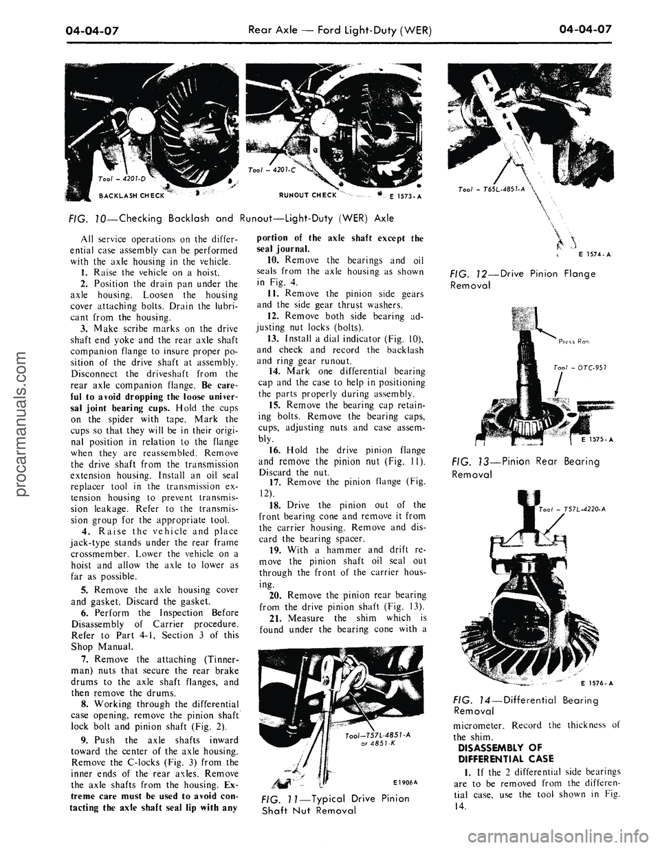
FIG. 70—Checking Backlash and Runout—Light-Duty (WER) Axle
All service operations on the differ-
ential case assembly can be performed
with the axle housing in the vehicle.
1.
Raise the vehicle on a hoist.
2.
Position the drain pan under the
axle housing. Loosen the housing
cover attaching bolts. Drain the lubri-
cant from the housing.
3.
Make scribe marks on the drive
shaft end yoke and the rear axle shaft
companion flange to insure proper po-
sition of the drive shaft at assembly.
Disconnect the driveshaft from the
rear axle companion flange. Be care-
ful to avoid dropping the loose univer-
sal joint bearing cups. Hold the cups
on the spider with tape. Mark the
cups so that they will be in their origi-
nal position in relation to the flange
when they are reassembled. Remove
the drive shaft from the transmission
extension housing. Install an oil seal
replacer tool in the transmission ex-
tension housing to prevent transmis-
sion leakage. Refer to the transmis-
sion group for the appropriate tool.
4.
Raise the vehicle and place
jack-type stands under the rear frame
crossmember. Lower the vehicle on a
hoist and allow the axle to lower as
far as possible.
5.
Remove the axle housing cover
and gasket. Discard the gasket.
6. Perform the Inspection Before
Disassembly of Carrier procedure.
Refer to Part 4-1, Section 3 of this
Shop Manual.
7.
Remove the attaching (Tinner-
man) nuts that secure the rear brake
drums to the axle shaft flanges, and
then remove the drums.
8. Working through the differential
case opening, remove the pinion shaft
lock bolt and pinion shaft (Fig. 2).
9. Push the axle shafts inward
toward the center of the axle housing.
Remove the C-locks (Fig. 3) from the
inner ends of the rear axles. Remove
the axle shafts from the housing. Ex-
treme care must be used to avoid con-
tacting the axle shaft seal lip with any
portion of the axle shaft except the
seal journal.
10.
Remove the bearings and oil
seals from the axle housing as shown
in Fig. 4.
11.
Remove the pinion side gears
and the side gear thrust washers.
12.
Remove both side bearing ad-
justing nut locks (bolts).
13.
Install a dial indicator (Fig. 10),
and check and record the backlash
and ring gear runout.
14.
Mark one differential bearing
cap and the case to help in positioning
the parts properly during assembly.
15.
Remove the bearing cap retain-
ing bolts. Remove the bearing caps,
cups,
adjusting nuts and case assem-
bly.
16.
Hold the drive pinion flange
and remove the pinion nut (Fig. 11).
Discard the nut.
17.
Remove the pinion flange (Fig.
12).
18.
Drive the pinion out of the
front bearing cone and remove it from
the carrier housing. Remove and dis-
card the bearing spacer.
19.
With a hammer and drift re-
move the pinion shaft oil seal out
through the front of the carrier hous-
ing.
20.
Remove the pinion rear bearing
from the drive pinion shaft (Fig. 13).
21.
Measure the shim which is
found under the bearing cone with a
Tool-T57L-485T-A
or 4851-K
El 906A
Tool
-
T6SL-485UA
\
E 1574-A
FIG. 12—Drive Pinion Flange
Removal
1575-A
FIG. 13—Pinion Rear Bearing
Removal
00/
- T57L-4220-A
FIG. 11—Typical Drive Pinion
Shaft Nut Removal
E 1576-A
FIG. 14—Differential Bearing
Removal
micrometer. Record the thickness of
the shim.
DISASSEMBLY OF
DIFFERENTIAL CASE
1.
If the 2 differential side bearings
are to be removed from the differen-
tial case, use the tool shown in Fig.
14.procarmanuals.com
Page 240 of 413
04-04-09
Rear Axle — Ford Light-Duty (WER)
04-04-09
case several revolutions in each direc-
tion while the bearings are loaded to
seat the bearings in their cups. This
step is important.
5. Again loosen the right nut to re-
lease the preload. Check to see that
the left nut contacts the bearing cup.
Using the dial indicator set-up shown
in Fig. 13, Part 4-1, adjust the preload
to 0.008 to 0.012 case spread for new
bearings or 0.005 to 0.008 for the
original bearings, if re-used.
6. Check the runout of the differen-
tial case flange with a dial indicator.
If the runout does not now exceed
specifications, install a new ring gear,
if the runout still exceeds specifica-
tions,
the ring gear is true and the
trouble is due to either a defective
casting or worn bearings.
7.
Remove the differential case
from the carrier and remove the side
bearings from the case.
8. Install new bearings on the case
hubs,
and again install the differential
assembly in the carrier without the
ring gear.
9. Check the case runout again with
the new bearings. If the runout is now
within limits, the old bearings were
excessively worn. Use the new bear-
ings for assembly. If the runout is still
excessive, the case is defective and
should be replaced.
ASSEMBLY OF AXLE
Refer to Part 4-1 of this Shop
Manual for Cleaning and Inspection
procedures before starting assembly
operations.
ASSEMBLY OF
DIFFERENTIAL CASE
1.
Place the ring gear on the differ-
ential case. Install the retaining bolts
and torque them to specification.
2.
If the differential bearings were
removed, press them on as shown in
Fig. 17.
3.
Insert the pinion gear shaft lock
bolt into the case (loosely).
INSTALLATION OF DRIVE
PINION AND
DIFFERENTIAL CASE
1.
Place the shim(s) and pinion rear
bearing cone on the pinion shaft.
Press the bearing and shim(s) firmly
against the pinion shaft shoulder (Fig.
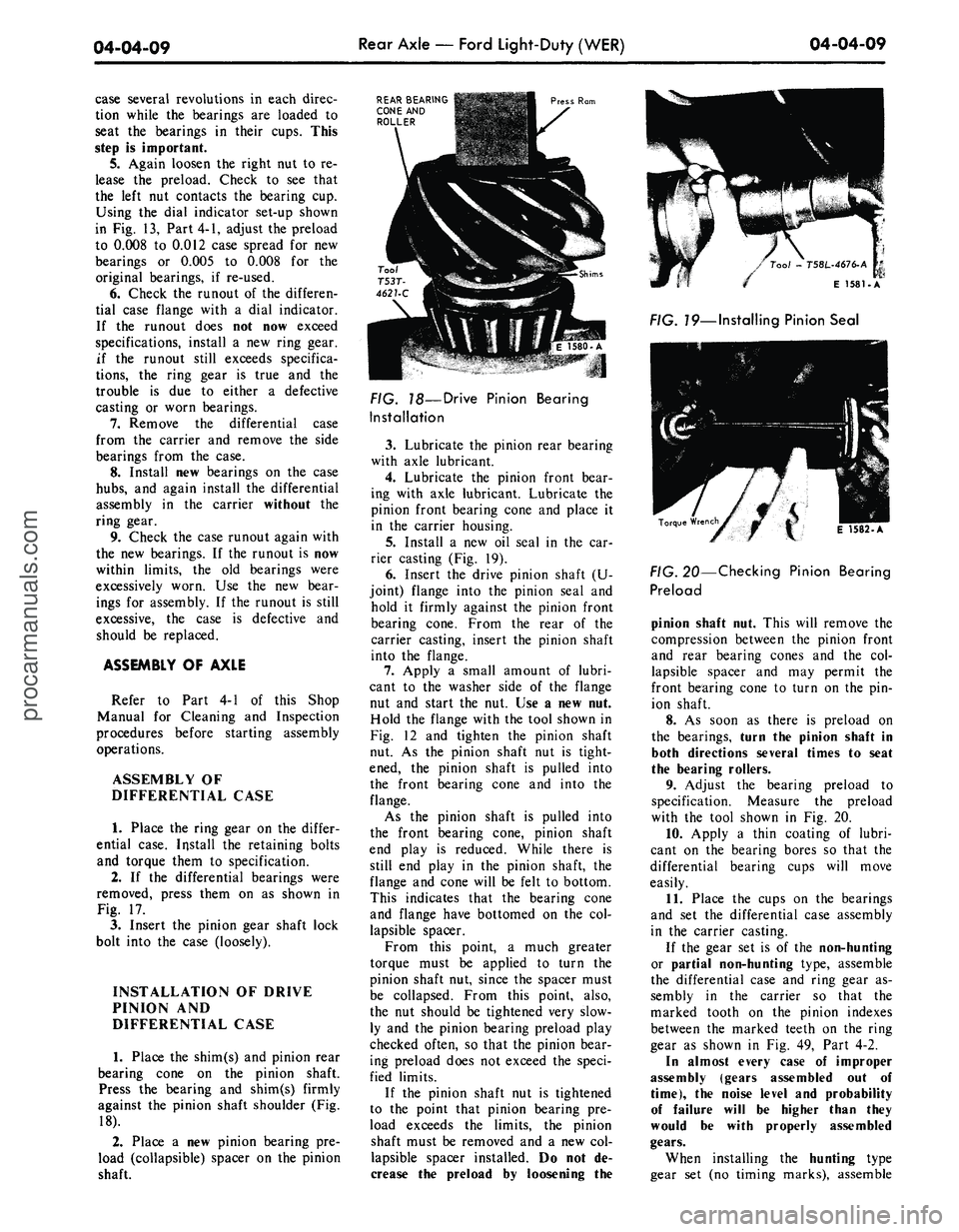
18).
2.
Place a new pinion bearing pre-
load (collapsible) spacer on the pinion
shaft.
REAR BEARING
CONE AND
ROLLER
Press Ram
FIG. 18—Drive Pinion Bearing
Installation
3.
Lubricate the pinion rear bearing
with axle lubricant.
4.
Lubricate the pinion front bear-
ing with axle lubricant. Lubricate the
pinion front bearing cone and place it
in the carrier housing.
5.
Install a new oil seal in the car-
rier casting (Fig. 19).
6. Insert the drive pinion shaft (U-
joint) flange into the pinion seal and
hold it firmly against the pinion front
bearing cone. From the rear of the
carrier casting, insert the pinion shaft
into the flange.
7.
Apply a small amount of lubri-
cant to the washer side of the flange
nut and start the nut. Use a new nut.
Hold the flange with the tool shown in
Fig. 12 and tighten the pinion shaft
nut. As the pinion shaft nut is tight-
ened, the pinion shaft is pulled into
the front bearing cone and into the
flange.
As the pinion shaft is pulled into
the front bearing cone, pinion shaft
end play is reduced. While there is
still end play in the pinion shaft, the
flange and cone will be felt to bottom.
This indicates that the bearing cone
and flange have bottomed on the col-
lapsible spacer.
From this point, a much greater
torque must be applied to turn the
pinion shaft nut, since the spacer must
be collapsed. From this point, also,
the nut should be tightened very slow-
ly and the pinion bearing preload play
checked often, so that the pinion bear-
ing preload does not exceed the speci-
fied limits.
If the pinion shaft nut is tightened
to the point that pinion bearing pre-
load exceeds the limits, the pinion
shaft must be removed and a new col-
lapsible spacer installed. Do not de-
crease the preload by loosening the
/
Tool
-
T58L-4676-A
/ E
1581-A
FIG. 19—Installing Pinion Seal
E 1582-A
FIG. 20—Checking Pinion Bearing
Preload
pinion shaft nut. This will remove the
compression between the pinion front
and rear bearing cones and the col-
lapsible spacer and may permit the
front bearing cone to turn on the pin-
ion shaft.
8. As soon as there is preload on
the bearings, turn the pinion shaft in
both directions several times to seat
the bearing rollers.
9. Adjust the bearing preload to
specification. Measure the preload
with the tool shown in Fig. 20.
10.
Apply a thin coating of lubri-
cant on the bearing bores so that the
differential bearing cups will move
easily.
11.
Place the cups on the bearings
and set the differential case assembly
in the carrier casting.
If the gear set is of the non-hunting
or partial non-hunting type, assemble
the differential case and ring gear as-
sembly in the carrier so that the
marked tooth on the pinion indexes
between the marked teeth on the ring
gear as shown in Fig. 49, Part 4-2.
In almost every case of improper
assembly (gears assembled out of
time),
the noise level and probability
of failure will be higher than they
would be with properly assembled
gears.
When installing the hunting type
gear set (no timing marks), assembleprocarmanuals.com
Page 245 of 413
04-05-04
Specifications
04-05-04
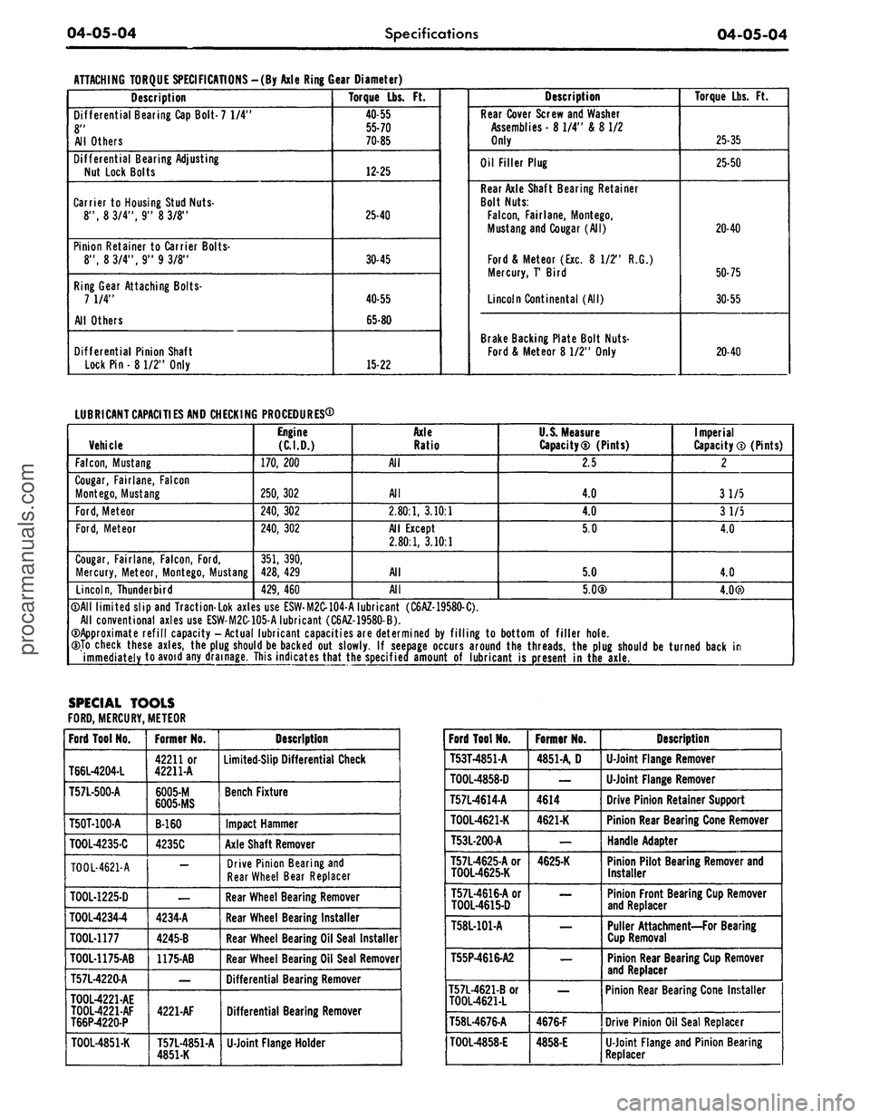
ATTACHING TORQUE SPECIFICATIONS -(By Axle Ring Gear Diameter)
Description
Differential Bearing Cap Bolt- 7 1/4"
8"
All Others
Differential Bearing Adjusting
Nut Lock Bolts
Carrier
to
Housing Stud Nuts-
8", 8 3/4", 9" 8 3/8"
Pinion Retainer
to
Carrier Bolts-
8", 8 3/4", 9" 9 3/8"
Ring Gear Attaching Bolts-
7 1/4"
All Others
Differential Pinion Shaft
Lock Pin
•
8 1/2" Only
Torque Lbs.
Ft.
40-55
55-70
70-85
12-25
25-40
30-45
40-55
65-80
15-22
Description
Rear Cover Screw and Washer
Assemblies
-8
1/4" &
8
1/2
Only
Oil Filler Plug
Rear Axle Shaft Bearing Retainer
Bolt Nuts:
Falcon,
Fairlane, Montego,
Mustang and Cougar (All)
Ford & Meteor (Exc.
8 1/2" R.G.)
Mercury,
T
Bird
Lincoln Continental (All)
Brake Backing Plate Bolt Nuts-
Ford & Meteor
8
1/2" Only
Torque Lbs.
Ft.
25-35
25-50
20-40
50-75
30-55
20-40
LUBRICANT
CAPACITIES
AND CHECKING PROCEDURES®
Vehicle
Falcon,
Mustang
Cougar, Fairlane, Falcon
Montego, Mustang
Ford,
Meteor
Ford,
Meteor
Cougar, Fairlane, Falcon, Ford,
Mercury, Meteor, Montego, Mustang
Lincoln,
Thunderbird
Engine
(C.I.D.)
170,
200
250,
302
240,
302
240,
302
351,
390,
428,
429
429,
460
Axle
Ratio
All
All
2.80:1,
3.10:1
All Except
2.80:1,
3.10:1
All
All
U.S. Measure
Capacity® (Pints)
2.5
4.0
4.0
5.0
5.0
5.0©
Imperial
Capacity
CD
(Pints)
2
31/5
3 1/5
4.0
4.0
4.0©
©All limited slip and Traction-Lok axles use ESW-M2C-104-A lubricant (C6AZ-19580-C).
All conventional axles use ESW-M2C-105-A lubricant (C6AZ-19580-B).
©Approximate refill capacity-Actual lubricant capacities are determined
by
filling
to
bottom
of
filler hole.
©To check these axles, the plug should be backed
out
slowly.
If
seepage occurs around the threads, the plug should
be
turned back
in
immediately to avoid any drainage. This indicates that the specified amount
of
lubricant
is
present
in
the axle.
SPECIAL TOOLS
FORD,
MERCURY, METEOR
Ford Tool No.
T66L-4204-L
T57L-500-A
T50T-100-A
TOOL-4235-C
T00L-4621-A
TOOL-1225-D
T00L42344
TOOL-1177
TOOL-U75-AB
T57L4220-A
T00L4221-AE
T00L-4221-AF
T66P-4220-P
TOOL-4851-K
Former No.
42211 or
42211-A
6005-M
6005-MS
B-160
4235C
—
—
4234-A
4245-B
1175-AB
—
4221-AF
T57L-4851-A
4851-K
Description
Limited-Slip Differential Check
Bench Fixture
Impact Hammer
Axle Shaft Remover
Drive Pinion Bearing and
Rear Wheel Bear Replacer
Rear Wheel Bearing Remover
Rear Wheel Bearing Installer
Rear Wheel Bearing Oil Seal Installer
Rear Wheel Bearing Oil Seal Remover
Differential Bearing Remover
Differential Bearing Remover
U-Joint
Flange Holder
Ford Tool No.
T53T4851-A
T00L4858-D
T57L4614-A
T00L4621-K
T53L-200-A
T57L-4625-A or
T00L4625-K
T57L4616-A or
T00L4615-D
T58L-101-A
T55P4616-A2
T57L4621-B or
T00L4621-L
T58L4676-A
T00L4858-E
Former No.
4851-A, D
—
4614
4621-K
—
4625-K
—
—
—
—
4676-F
4858-E
Description
U-Joint
Flange Remover
U-Joint
Flange Remover
Drive Pinion Retainer Support
Pinion Rear Bearing Cone Remover
Handle Adapter
Pinion Pilot Bearing Remover and
Installer
Pinion Front Bearing Cup Remover
and Replacer
Puller Attachment—For Bearing
Cup Removal
Pinion Rear Bearing Cup Remover
and Replacer
Pinion Rear Bearing Cone Installer
Drive Pinion Oil Seal Replacer
U-Joint
Flange and Pinion Bearing
Replacerprocarmanuals.com
Page 295 of 413
07-01-04
General Transmission Service
07-01-04
taching bolts to the proper torque. If
necessary, replace the gasket.
Check the fluid filler tube connec-
tion at the transmission case or pan.
If leakage is found here, install a new
O-ring or tighten the fitting to the
specified torque.
Check the fluid lines and fittings
between the transmission and the
cooler in the radiator tank for loose-
ness,
wear, or damage. If leakage can-
not be stopped by tightening a fitting,
replace the damaged parts.
Check the engine coolant in the ra-
diator. If transmission fluid is present
in the coolant, the cooler in the radia-
tor is probably leaking.
The cooler can be further checked
for leaks by disconnecting the lines
from the cooler fittings and applying
50-75 psi air pressure to the fittings.
Remove the radiator cap to relieve the
pressure build at the exterior of the oil
cooler tank. If the cooler is leaking
and will not hold this pressure the
cooler must be replaced. Cooler re-
placement is described in the Cooling
System Section of Group 11.
If leakage is found at either the
downshift control lever shaft or the
manual lever shaft, replace either or
both seals.
Inspect the pipe plug on the left
side of the transmission case at the
front. If the plug shows leakage, tor-
que the plug to specifications. If tight-
ening does not stop the leaks, replace
the plug. On a C6 transmission, a TV
pressure plug is also provided on the
right rear side of the case.
When converter drain plugs leak,
remove drain plugs with a six-point
wrench. Coat the threads with FoMo-
Co Perfect Seal Sealing Compound or
its equivalent, and install the plugs.
Torque the drain plugs to specifica-
tion. Fluid leakage from the converter
housing may be caused by engine oil
leaking past the rear main bearing or
from oil gallery plugs, or power steer-
ing oil leakage from steering system.
Be sure to determine the exact cause
of the leak before repair procedures
are started.
Oil-soluble aniline or fluorescent dyes
premixed at the rate of 1/2 teaspoon
of dye powder to 1/2 pint of transmis-
sion fluid have proved helpful in locat-
ing the source of the fluid leakage.
Such dyes may be used to determine
whether an engine oil or transmission
fluid leak is present or if the fluid in
the oil cooler leaks into the engine
coolant system. A black light, how-
ever, must be used with the fluorescent
dye solution.
DISHED OR
FLAT WASHER
" O.D.,
a" STEEL PLATE
5/8"X \W,
DRILL TO SUIT
HEX. HEAD SCREW
3/8"-24 X Vl
HEX. NUT W—
24
WELD
TOGETHER
WING
NUT
>/2"_13
THREAD
CHAIN,
10"
LONG
RUBBER PLUG
1
Vi" DIA. X 2"
LONG Vl"
HOLE THRU
APPROXIMATELY
40 DUROMETER
FLAT WASHER
Vs" O.D.
PLUG
VALVE
STANDARD BOLT
W-13
X 4Vl"
LONG SQUARE
THREAD
END
REMOVE HEAD
AND WELD
TO
WASHER
STANDARD 1/8" FITTING-87971-S FOR
RETAPPED DRAIN PLUG THREADS-USE
1/4" OVERSIZE FITTING-87973-S
D 1067-B
WELD TOGETHER
SECURELY—MUST
NOT LEAK
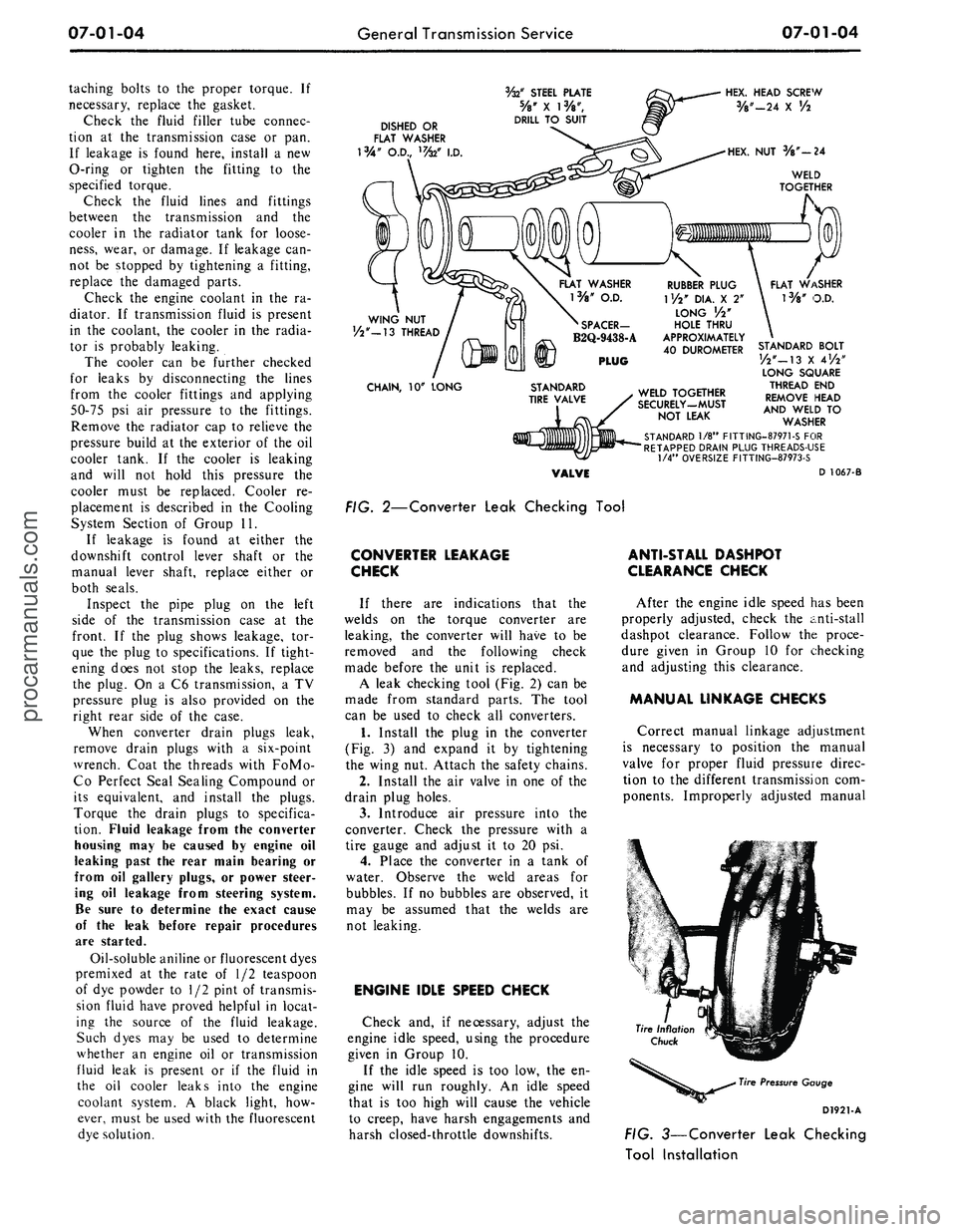
FIG. 2—Converter Leak Checking Tool
CONVERTER LEAKAGE
CHECK
If there are indications that the
welds on the torque converter are
leaking, the converter will have to be
removed and the following check
made before the unit is replaced.
A leak checking tool (Fig. 2) can be
made from standard parts. The tool
can be used to check all converters.
1.
Install the plug in the converter
(Fig. 3) and expand it by tightening
the wing nut. Attach the safety chains.
2.
Install the air valve in one of the
drain plug holes.
3.
Introduce air pressure into the
converter. Check the pressure with a
tire gauge and adjust it to 20 psi.
4.
Place the converter in a tank of
water. Observe the weld areas for
bubbles. If no bubbles are observed, it
may be assumed that the welds are
not leaking.
ENGINE IDLE SPEED CHECK
Check and, if necessary, adjust the
engine idle speed, using the procedure
given in Group 10.
If the idle speed is too low, the en-
gine will run roughly. An idle speed
that is too high will cause the vehicle
to creep, have harsh engagements and
harsh closed-throttle downshifts.
ANTI-STALL DASHPOT
CLEARANCE CHECK
After the engine idle speed has been
properly adjusted, check the anti-stall
dashpot clearance. Follow the proce-
dure given in Group 10 for checking
and adjusting this clearance.
MANUAL LINKAGE CHECKS
Correct manual linkage adjustment
is necessary to position the manual
valve for proper fluid pressure direc-
tion to the different transmission com-
ponents. Improperly adjusted manual
Tire Pressure Gauge
D1921-A
FIG. 3—Converter Leak Checking
Tool Installationprocarmanuals.com