check engine FORD MUSTANG 1969 Volume One Chassis
[x] Cancel search | Manufacturer: FORD, Model Year: 1969, Model line: MUSTANG, Model: FORD MUSTANG 1969Pages: 413, PDF Size: 75.81 MB
Page 12 of 413
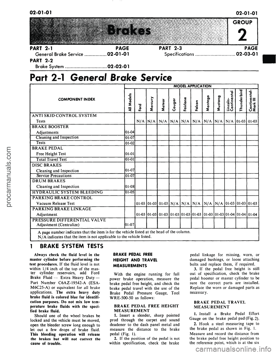
02-01-01
02-01-01
GROUP
2
PART
2-1
PAGE
General Brake Service 02-01-01
PART
2-2
Brake System 02-02-01
PART
2-3
Specifications
PAGE
02-03-01
Part
2-1
General Brake Service
COMPONENT INDEX
ANTI SKID CONTROL SYSTEM
Tests
BRAKE BOOSTER
Adjustments
Cleaning
and
Inspection
Tests
BRAKE PEDAL
Free Height Test
Total Travel Test
DISC BRAKES
Cleaning
and
Inspection
Service Precautions
DRUM BRAKES
Cleaning
and
Inspection
HYDRAULIC SYSTEM BLEEDING
PARKING BRAKE CONTROL
Vacuum Release Test
PARKING BRAKE LINKAGE
Adjustment
PRESSURE DIFFERENTIAL VALVE
Adjustment (Centralize)
MODEL APPLICATION
All
Models
01-04
01-07
01-02
01-01
01-01
01-07
01-07
01-08
01-05
01-07
Ford
N/A
01-03
01-03
Mercury
N/A
01-03
01-03
Meteor
N/A
01-03
01-03
Cougar
N/A
N/A
01-03
Fairlane
N/A
N/A
01-03
F
alcon
N/A
N/A
01-03
Montego
N/A
N/A
01-03
Mustang
N/A
N/A
01-03
Lincoln-
Continental
N/A
01-03
01-04
Thunderbird
01-03
01-03
01-04
Continental-
Mark III
01-03
01-03
01-04
A page number indicates that the item
is for the
vehicle listed
at
the head
of the
column.
N/A indicates that the item
is not
applicable
to
the vehicle listed.
1 BRAKE SYSTEM TESTS
Always check
the
fluid level
in the
master cylinder before performing
the
test procedures.
If the
fluid level
is not
within
1/4
inch
of the top of the mas-
ter cylinder reservoirs,
add
Ford
Brake Fluid
—
Extra Heavy Duty —
Part Number C6AZ-19542-A
(ESA-
M6C25-A)
or
equivalent
for all
brake
applications.
The
extra heavy duty
brake fluid
is
colored blue
for
identifi-
cation purposes.
Do not mix low tem-
perature brake fluids with
the
speci-
fied brake fluid.
Should
one of the
wheel brakes
be
locked
and the
vehicle must
be
moved,
open
the
bleeder screw long enough
to
let
out a few
drops
of
brake fluid.
This bleeding operation will release
the brakes
but
will
not
correct
the
cause
of
trouble.
BRAKE PEDAL FREE
HEIGHT
AND
TRAVEL
MEASUREMENTS
With
the
engine running
for
full
power brake operation, measure
the
brake pedal free height,
and
check
the
brake pedal travel with
the use of the
Brake Pedal Pressure Gauge, Tool
WRE-5OO-5O
as
follows:
BRAKE PEDAL FREE HEIGHT
MEASUREMENT
1.
Insert
a
slender, sharp pointed
prod through
the
carpet
and
sound
deadener
to the
dash panel metal
and
measure
the
distance
to the
brake
pedal
(Fig. 1).
2.
If the
position
of the
pedal
is not
within specification, check
the
brake
pedal linkage
for
missing, worn,
or
damaged bushings,
or
loose attaching
bolts
and
replace them,
if
required.
3.
If the
pedal free height
is
still
out
of
specification, check
the
brake
pedal booster
or
master cylinder
to be
sure
the
correct parts
are
installed.
Replace
the
worn
or
damaged parts
as
necessary.
BRAKE PEDAL TRAVEL
MEASUREMENT
1.
Install
a
Brake Pedal Effort
Gauge
on the
brake pedal
pad
(Fig. 2).
2.
Hook
a
steel measuring tape
to
the brake pedal
as
shown
in Fig. 1.
Measure
and
record
the
distance from
the brake pedal free height position
to
the reference point, which
is at the six
procarmanuals.com
Page 13 of 413
02-01-02
Brakes
02*01-02
STEERING
WHEEL RIW
TOEBOARD
OR
DASH
METAL
CHECKING
POINTS
STEERING
COLUMN-
STEEL
MEASURING TAPE
VEHICLE
FORD,
MERCURY AND METEOR
FORD,
MERCURY AND METEOR
FORD,
MERCURY AND METEOR
FORD,
MERCURY AND METEOR
FAIRLANE,
MONTEGO AND FALCON
FAIRLANE,
MONTEGO AND FALCON
MUSTANG
AND COUGAR
MUSTANG
AND COUGAR
THUNDERBIRD
CONTINENTAL
MARK III
LINCOLN
CONTINENTAL
TYPE
NON-POWER
DRUM
POWER
DRUM & DISC
NON-POWER
DISC
POLICE
POWER DISC
NON-POWER
DRUM
POWER
DISC
NON-POWER
DRUM
POWER
DISC
POWER
DISC
POWER
DISC
POWER
DISC
PEDAL
FREE
HEIGHT-A
8.09-7.17
6.18-5.99
8.65-7.82
7.58-6.72
8.13-6.91
7.25-5.71
7.49-6.43
6.25-5.56
PEDAL
FREE
HEIGHT-B"
5.96-5.04
5.96-5.04
6.50-5.50
PEDAL
TRAVEL-C
3.10
3.27
2.18
3.27
2.90
2.35
2.58
1.75
3.00
3.00
2.25
NOTE:AgB
DIMENSION TO BE MEASURED TO SHEET METAL
C
DIMENSION TO BE MEASURED PARALLEL TO THE VERTICAL CENTERLINE OF THE
STEERING
COLUMN WITH A 50 POUND LOAD APPLIED TO THE CENTERLINE OF THE
BRAKE
PEDAL PAD. (CHECKS ON POWER BRAKE VEHICLES MADE WITH ENGINE RUNNING
H1630-A
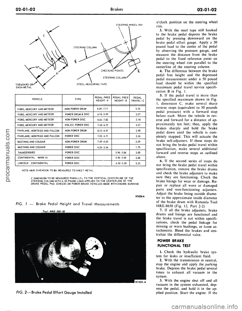
FIG. 1 — Brake Pedal Height and Travel Measurements
Tool-WRE-l
HI525-A
FIG.
2—Brake Pedal Effort Gauge Installed
o'clock position on the steering wheel
rim.
3.
With the steel tape still hooked
to the brake pedal depress the brake
pedal by pressing downward on the
brake pedal effort gauge. Apply a 50
pound load to the center of the pedal
by observing the pressure gauge, and
measure the distance from the brake
pedal to the fixed reference point on
the steering wheel rim parallel to the
centerline of the steering column.
4.
The difference between the brake
pedal free height and the depressed
pedal measurement under a 50 pound
load should be within the specified
maximum pedal travel service specifi-
cation B in Fig. I.
5.
If the pedal travel is more than
the specified maximum shown in Fig.
1,
dimension C, make several sharp
reverse stops (equivalent to 50 pounds
pedal pressure) with a forward stop
before each. Move the vehicle in rev-
erse and forward for a distance of ap-
proximately ten feet; then, apply the
brakes sharply and hold the brake
pedal down until the vehicle is com-
pletely stopped. This will actuate the
brake self-adjusters. If these stops do
not bring the brake pedal travel within
specification, make several additional
forward and reverse stops as outlined
above.
6. If the second series of stops do
not bring the brake pedal travel within
specification, remove the brake drums
and check the brake adjusters to make
sure they are functioning. Check the
brake linings for wear or damage. Re-
pair or replace all worn or damaged
parts and non-functioning adjusters.
Adjust the brake lining outside diame-
ter to the approximate inside diameter
of the brake drum with Rotunda Tool
HRE-8650 (Fig. 12, Part 2-2).
7.
If all the brake adjusters, brake
drums and linings are functional and
the brake travel is not within specifi-
cations, check the pedal linkage for
missing or worn bushings, or loose at-
tachments. Bleed the brakes and cen-
tralize the differential valve.
POWER BRAKE
FUNCTIONAL TEST
1.
Check the hydraulic brake sys-
tem for leaks or insufficient fluid.
2.
With the transmission in neutral,
stop the engine and apply the parking
brake. Depress the brake pedal several
times to exhaust all vacuum in the
system.
3.
With the engine shut off and all
vacuum in the system exhausted, dep-
ress the pedal, and hold it in the ap-
plied position. Start the engine If theprocarmanuals.com
Page 14 of 413
02-01-03
Brakes
02-01-03
vacuum system is operating, the pedal
will tend to fall away under foot pres-
sure and less pressure will be required
to hold the pedal in the applied posi-
tion. If no action is felt, the vacuum
booster system is not functioning.
If the brake pedal movement feels
spongy, bleed the hydraulic system to
remove air from the system. Refer to
Hydraulic System Bleeding, Part 1,
Section 2.
VACUUM TESTS—VACUUM
RELEASE PARKING BRAKES
Visually check the operation of the
brake linkage as the brake pedal is
depressed. Then, check the operation
of the brake linkage when the manual
release lever is activiated. These
checks should indicate whether the
manual parking brake control linkage
is operating properly or requires re-
pair or adjustment due to inability of
the parking brake to hold against
moderate vehicle movement. Perform
tests of the parking brake system and
controls after making certain the link-
age and manual controls operate
properly.
When testing a parking brake vacu-
um release system, a minimum of 10
inches of vacuum (Hg.) should be
available at all points where vacuum is
applied. This can be checked with a
Rotunda Fuel Pump Tester Gauge
(ARE345) and two Distributor Tester
hose adapters (Marked Q) connected
together with a coupling. This allows
the Fuel Pump Tester Gauge hose to
be adapted to any other vacuum hose
or rubber connector in the vacuum
systems.
Failure to maintain 10 inches of
vacuum (Hg.) during vacuum system
tests could be caused by a loose hose
connection, resulting in a vacuum
leak. When checking for vacuum be-
tween two points, trace the hose along
the entire routing to be sure it is not
crossed with another hose and con-
nected to the wrong connection.
All of the vacuum parking brake
control checks are to be performed
with the engine running at idle speed.
Leaks in the parking brake hoses or
a disconnected or improperly con-
nected hose can usually be found by
listening for a hissing sound along the
hose routings. Under no circumstances
should air pressure be applied to the
vacuum system as the actuator dia-
phragm in the parking brake vacuum
motor may be damaged.
1.
Start the engine and run it at
idle speed. With the transmission shift
control in neutral, depress the parking
brake pedal to apply the parking
brake. Move the transmission shift
control to D range and observe the
parking brake pedal to see that the
pedal moves upward and the parking
brake releases. If the parking brake
releases, the parking brake vacuum
control is working properly.
2.
If the parking brake does not re-
lease, test for vacuum at the steering
column neutral switch port in the
junction block, vacuum lines and the
parking brake release vacuum motor.
Use the Rotunda Vacuum and Fuel
Pump Tester 345. This can be accom-
plished by removing the hose from
each component and attaching it to
the vacuum gauge. Connect two dis-
tributor tester vacuum hose adapters
together with a coupling as a connec-
tor to attach the gauge. A minimum
of ten inches of vacuum is required to
actuate the parking brake vacuum
motor. Do not remove any of the vac-
uum hoses from the junction block
unless the junction block is being re-
placed, as the plastic nipples are thin
and very brittle and damage may re-
sult. If a minimum reading is not
present when checking each of the
aforementioned components, they
must be replaced.
ROAD TEST
A road test should be conducted
only when the operator is sure the
brakes will stop the vehicle.
If the road test reveals one or more
problem conditions, correct all mal-
functions of the vacuum system, brake
booster and hydraulic system prior to
removing brake drums, brake calipers,
brake shoes and linings or backing
plates.
ANTI-SKID CONTROL
SYSTEM TESTS
No adjustments or repairs are to be
performed on the skid control system.
Damaged or worn parts are to be re-
placed.
Refer to Ford Car and Truck Diag-
nosis Manual for Testing procedures.
COMMON ADJUSTMENTS AND REPAIRS
PARKING BRAKE LINKAGE
ADJUSTMENT
FORD, MERCURY, METEOR,
FAIRLANE, MONTEGO,
FALCON, MUSTANG
AND COUGAR
Check the parking brake cables
when the brakes are fully released. If1
the cables are loose, adjust them as
follows:
1.
Fully release the parking brake
pedal by pulling the release lever.
2.
Depress the parking brake pedal
until it is engaged in the first notch of
the control. On a vacuum release
brake, the first notch will be approxi-
mately two inches of pedal travel.
3.
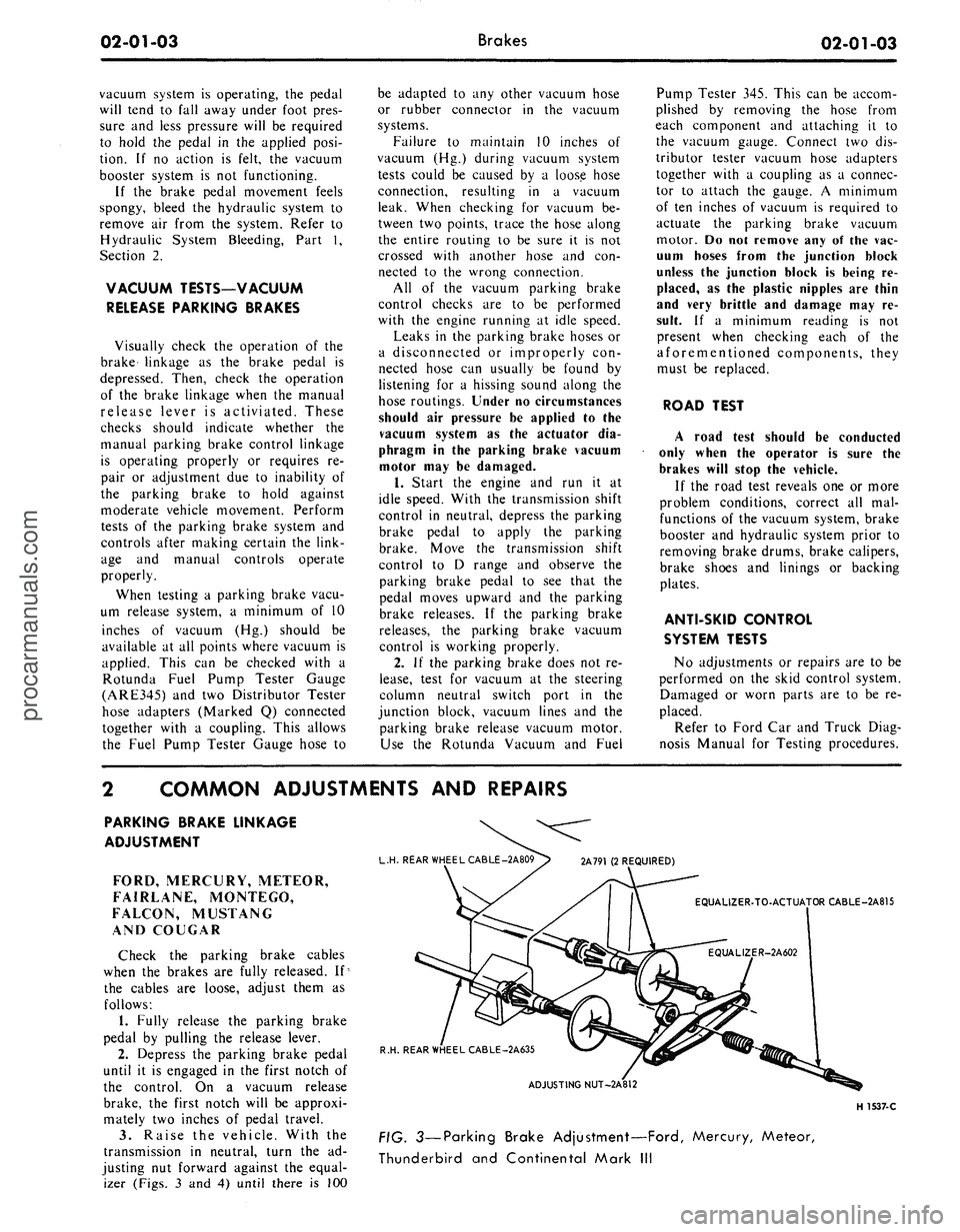
Raise the vehicle. With the
transmission in neutral, turn the ad-
justing nut forward against the equal-
izer (Figs. 3 and 4) until there is 100
L.H. REAR WHEEL CABLE -2A809> 2A791 (2 REQUIRED)
EQUALIZER-TO-ACTUATOR CABLE-2A815
R.H. REAR WHEEL CABLE-2A635
ADJUSTING NUT-2A812
H 1537-C
FIG. 3—Parking Brake Adjustment—Ford, Mercury, Meteor,
Thunderbird and Continental Mark IIIprocarmanuals.com
Page 15 of 413
02-01-04
Brakes
02-01-04
ft-lb breakaway torque.
The
breaka-
way torque
is the
torque required
to
turn
the
rear wheels
the
direction
of
forward rotation with
a
torque wrench
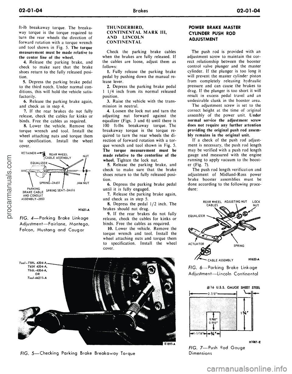
and tool shown
in Fig. 5. The
torque
measurement must
be
made relative
to
the center line
of the
wheel.
4.
Release
the
parking brake,
and
check
to
make sure that
the
brake
shoes return
to the
fully released posi-
tion.
5.
Depress
the
parking brake pedal
to
the
third notch. Under normal
con-
ditions, this will hold
the
vehicle satis-
factorily.
6. Release
the
parking brake again,
and check
as in
step
4.
7.
If the
rear brakes
do not
fully
release, check
the
cables
for
kinks
or
binds.
Free
the
cables
as
required.
8. Lower
the
vehicle. Remove
the
torque wrench
and
tool. Install
the
wheel attaching nuts
and
torque them
to specification. Install
the
wheel
cover.
RETAINER-*^ REAR WHEEL
(CABLE ASSEMBLY
EQUALIZER
NUT
PARKING
BRAKE CABLE
AND CONDUIT
ASSEMBLY-2853
SPRING-2A651
SPRING SEAT-2A616
JAM NUT
H1631-A
FIG. 4—Parking Brake Linkage
Adjustment—Fairlane, Montego,
Falcon,
Mustang
and
Cougar
THUNDERBIRD,
CONTINENTAL MARK
III,
AND LINCOLN
CONTINENTAL
Check
the
parking brake cables
when
the
brakes
are
fully released.
If
the cables
are
loose, adjust them
as
follows:
1.
Fully release
the
parking brake
pedal
by
pushing down
the
manual
re-
lease lever.
2.
Depress
the
parking brake pedal
1
1/4
inch from
its
normal released
position.
3.
Raise
the
vehicle with
the
trans-
mission
in
neutral.
4.
Loosen
the
lock
nut and
turn
the
adjusting
nut
forward against
the
equalizer (Figs.
3 and 6)
until there
is
100 ft-lbs breakaway torque.
The
breakaway torque
is the
torque
re-
quired
to
turn
the
rear wheels
the di-
rection
of
forward rotation with
a tor-
que wrench
and
tool shown
in Fig. 5.
The torque measurement must
be
made relative
to the
centerline
of the
wheel. Tighten
the
lock
nut.
5.
Release
the
parking brake,
and
check
to
make sure that
the
brake
shoes return
to the
fully released posi-
tion.
6. Depress
the
parking brake pedal
until
it is
fully engaged.
7.
Release
the
parking brake again,
and check
as in
step
5.
8. Depress
the
pedal
1/2
inch.
The
brakes should
not
drag.
9.
If the
rear brakes
do not
fully
release, check
the
cables
for
kinks
or
binds.
Free
the
cables
as
required.
10.
Lower
the
vehicle. Remove
the
torque wrench
and
tool. Install
the
wheel attaching nuts
and
torque them
to specification. Install
the
wheel
cover.
Tool-T59L
4204-A,
T65K
4204-A,
T66L-4204-A,
OR
Tool-4421UA
E1897-A
POWER BRAKE MASTER
CYLINDER PUSH
ROD
ADJUSTMENT
The push
rod is
provided with
an
adjustment screw
to
maintain
the cor-
rect relationship between
the
booster
control valve plunger
and the
master
cylinder.
If the
plunger
is too
long
it
will prevent
the
master cylinder piston
from completely releasing hydraulic
pressure
and can
cause
the
brakes
to
drag.
If the
plunger
is too
short
it
will
result
in
excess pedal travel
and an
undesirable clunk
in the
booster area.
The adjustment screw
is set to the
correct height
at the
time
of
original
assembly
of the
power unit. Under
normal service
the
adjustment screw
does
not
require
any
further attention
providing
the
original push
rod
assem-
bly remains
in the
original unit.
If
a
check
of the
push
rod
adjust-
ment
is
necessary,
the
push
rod
length
may
be
verified with
a
push
rod
length
gauge
and
measured with
the
engine
running
to
apply vacuum
to the
boost-
er (Fig.
7).
The push
rod
length verification
and
adjustment
of
Midland-Ross power
brake booster assemblies must
be
done according
to the
following proce-
dure:
REAR WHEEL ADJUSTING NUT
CABLES
EQUALIZER
SPRING
CABLE ASSEMBLY H1632-A
FIG. 6—Parking Brake Linkage
Adjustment—Lincoln Continental
FIG. 5—Checking Parking Brake Breakaway Torque
#16
U.J
\
0.980"
0.995"
FIG. 7—Push
Dimensions
>.S. GAUGE SHEET
i
1
STEEL
H1087-E
Rod Gaugeprocarmanuals.com
Page 25 of 413
02-02-06
Brake
System
02-02-06
SHOE GUIDE (ANCHOR
PIN)
PLATE
SHOE GUIDE (ANCHOR
PIN)
PLATE
WASHER
PRIMARY SHOE
-TC
-ANCHOR
SPRING
PARKING
BRAKE LEVER
RETAINING
CLIP
SECONDARY
SHOE
PRIMARY
SHOE
CABLE HOOK
PARKING
BRAKE CABLE
AND HOUSING
PIVOT
NUT
AUTOMATIC
ADJUSTER
SPRING
H
1649-
A
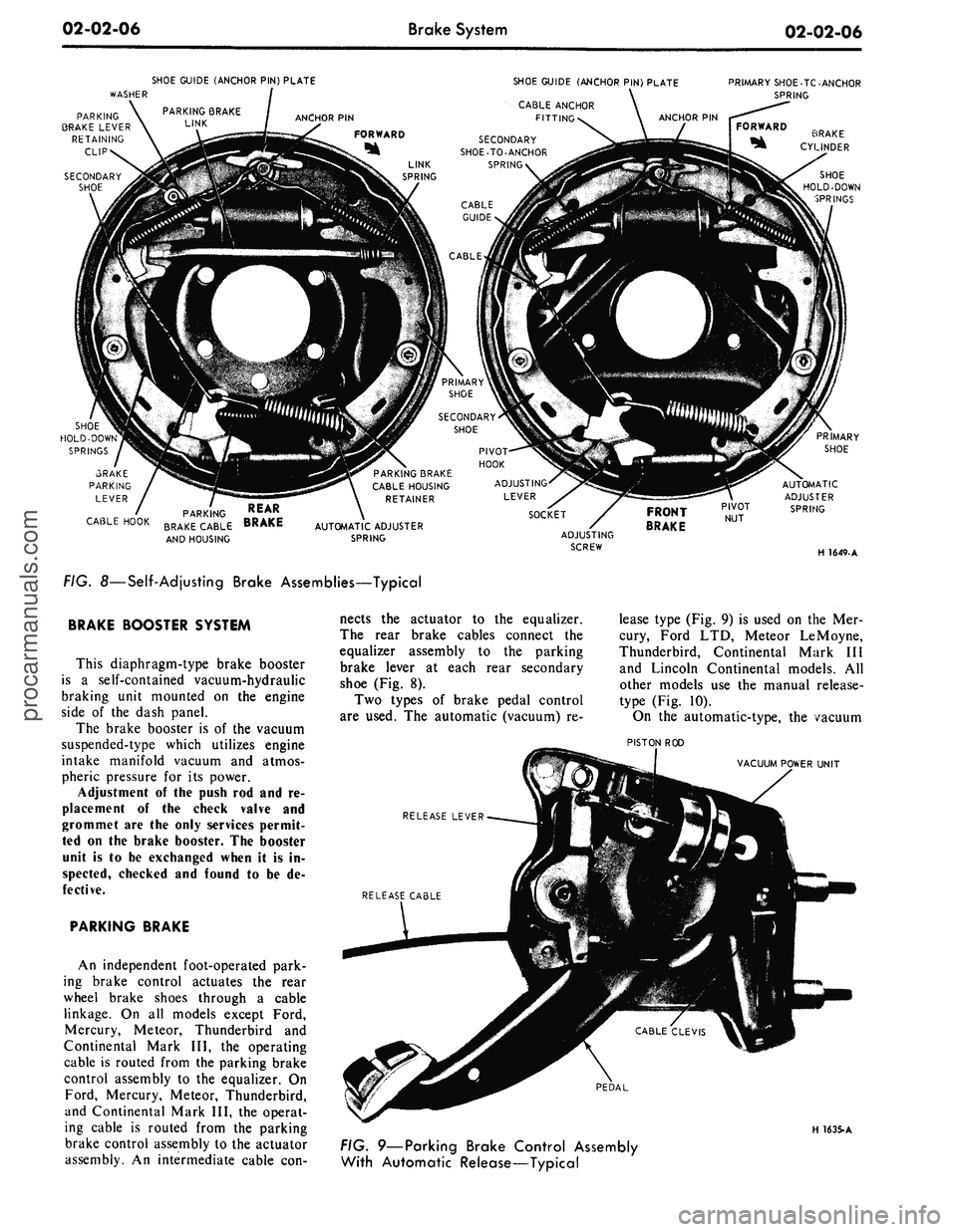
FIG. 8—Self-Adjusting Brake Assemblies—Typical
BRAKE BOOSTER SYSTEM
This diaphragm-type brake booster
is
a
self-contained vacuum-hydraulic
braking unit mounted
on the
engine
side
of the
dash panel.
The brake booster
is of the
vacuum
suspended-type which utilizes engine
intake manifold vacuum
and
atmos-
pheric pressure
for its
power.
Adjustment
of the
push
rod and re-
placement
of the
check valve
and
grommet
are the
only services permit-
ted
on the
brake booster.
The
booster
unit
is to be
exchanged when
it is in-
spected, checked
and
found
to be de-
fective.
PARKING BRAKE
An independent foot-operated park-
ing brake control actuates
the
rear
wheel brake shoes through
a
cable
linkage.
On all
models except Ford,
Mercury, Meteor, Thunderbird
and
Continental Mark
III, the
operating
cable
is
routed from
the
parking brake
control assembly
to the
equalizer.
On
Ford, Mercury, Meteor, Thunderbird,
and Continental Mark
III, the
operat-
ing cable
is
routed from
the
parking
brake control assembly
to the
actuator
assembly.
An
intermediate cable
con-
nects
the
actuator
to the
equalizer.
The rear brake cables connect
the
equalizer assembly
to the
parking
brake lever
at
each rear secondary
shoe
(Fig. 8).
Two types
of
brake pedal control
are used.
The
automatic (vacuum)
re-
lease type
(Fig. 9) is
used
on the Mer-
cury, Ford
LTD,
Meteor LeMoyne,
Thunderbird, Continental Mark
III
and Lincoln Continental models.
All
other models
use the
manual release-
type
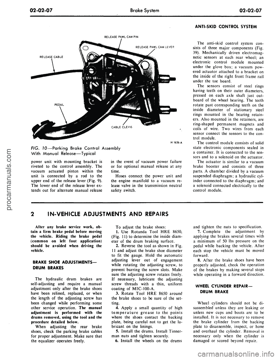
(Fig. 10).
On
the
automatic-type,
the
vacuum
PISTON
ROD
VACUUM POWER UNIT
RELEASE LEVER
PEDAL
H 1635-A
FIG. 9—Parking Brake Control Assembly
With Automatic Release—Typicalprocarmanuals.com
Page 26 of 413
02-02-07
Brake System
02-02-07
ANTI-SKID CONTROL SYSTEM
RELEASE PAWL CAM PIN
RELEASE PAWL CAM LEVER
RELEASE CABLE
H
1636-
A
FIG. 10—Parking Brake Control Assembly
With Manual Release—Typical
power unit with mounting bracket is
riveted to the control assembly. The
vacuum actuated piston within the
unit is connected by a rod to the
upper end of the release lever (Fig. 9).
The lower end of the release lever ex-
tends out for alternate manual release
in the event of vacuum power failure
or for optional manual release at any
time.
Hoses connect the power unit and
the engine manifold to a vacuum re-
lease valve in the transmission neutral
safety switch.
The anti-skid control system con-
sists of three major components (Fig.
39).
Mechanically driven electromag-
netic sensors at each rear wheel; an
electronic control module mounted
under the glove box; a vacuum pow-
ered actuator attached to a bracket on
the inside of the right front frame rail
under the toe board.
The sensors consist of steel rings
having teeth on their outer diameters,
pressed on each axle shaft just out-
board of the wheel bearing. The teeth
rotate past corresponding teeth on the
inside diameter of stationary steel
rings mounted in the bearing retain-
ers.
Also mounted in the retainers, are
ring-shaped permanent magnets and
coils of wire. Two wires from each
sensor connect the sensors to the con-
trol module.
The control module consists of solid
state electronic components sealed in
a container. It is connected to the sen-
sors and to a solenoid on the actuator.
The actuator is similar to a vacuum
brake booster and consists of three
parts.
A chamber divided by a vacuum
suspended diaphragm; a hydraulic cyl-
inder connected to the diaphragm; and
a solenoid connected electrically to the
control module.
IN-VEHICLE ADJUSTMENTS AND REPAIRS
After any brake service work, ob-
tain a firm brake pedal before moving
the vehicle. Riding the brake pedal
(common on left foot application)
should be avoided when driving the
vehicle.
BRAKE SHOE ADJUSTMENTS—
DRUM BRAKES
The hydraulic drum brakes are
self-adjusting and require a manual
adjustment only after the brake shoes
have been relined, replaced, or when
the length of the adjusting screw has
been changed while performing some
other service operation. The manual
adjustment is performed with the
drums removed, using the tool and the
procedure detailed below.
When adjusting the rear brake
shoes,
check the parking brake cables
for proper adjustment. Make sure that
the equalizer operates freely.
To adjust the brake shoes:
1.
Use Rotunda Tool HRE 8650,
(Fig. 11) to determine the inside diam-
eter of the drum braking surface.
2.
Reverse the tool as shown in Fig.
11 and adjust the brake shoe diameter
to fit the gauge. Hold the automatic
adjusting lever out of engagement
while rotating the adjusting screw, to
prevent burring the screw slots. Make
sure the adjusting screw rotates freely.
If necessary, lubricate the adjusting
screw threads with a thin, uniform
coating of MIC-100-A.
3.
Rotate Tool HRE 8650 around
the brake shoes to be sure of the set-
ting.
4.
Apply a small quantity of high
temperature grease to the points
where the shoes contact the backing
plate, being careful not to get the lu-
bricant on the linings.
5. Install the drums. Install Tinner-
man nuts and tighten securely.
6. Install the wheels on the drums
and tighten the nuts to specification.
7.
Complete the adjustment by
applying the brakes several times with
a minimum of 50 lbs pressure on the
pedal while backing the vehicle. After
each stop the vehicle must be moved
forward.
8. After the brake shoes have been
properly adjusted, check the operation
of the brakes by making several stops
while operating in a forward direction.
WHEEL CYLINDER REPAIR-
DRUM BRAKE
Wheel cylinders should not be di-
sassembled unless they are leaking or
unless new cups and boots are to be
installed. It is not necessary to remove
the brake cylinder from the backing
plate to disassemble, inspect, or hone
and overhaul the cylinder. Removal is
necessary only when the cylinder is
damaged or scored beyond repair.procarmanuals.com
Page 29 of 413
02-02-10
Brake System
02-02-10
brake adjustment then connect the
parking brake cable to the parking
brake lever (Fig. 8).
4.
Install the shoe guide (anchor
pin) plate on the anchor pin when so
equipped.
5.
Place the cable eye over the an-
chor pin with the crimped side toward
the backing plate.
6. Install the primary shoe to an-
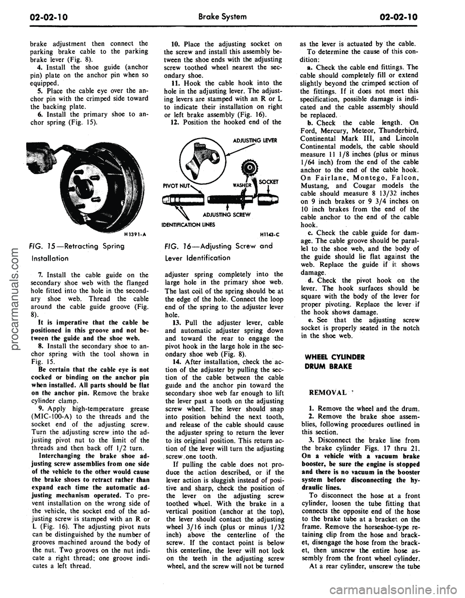
chor spring (Fig. 15).
H1391-A
FIG. 75—Retracting Spring
Installation
7.
Install the cable guide on the
secondary shoe web with the flanged
hole fitted into the hole in the second-
ary shoe web. Thread the cable
around the cable guide groove (Fig.
8).
It
is
imperative that
the
cable
be
positioned
in
this groove
and not be-
tween
the
guide
and the
shoe
web.
8.
Install the secondary shoe to an-
chor spring with the tool shown in
Fig. 15.
Be certain that
the
cable
eye is not
cocked
or
binding
on the
anchor
pin
when installed.
All
parts should
be
flat
on
the
anchor
pin.
Remove
the
brake
cylinder clamp.
9. Apply high-temperature grease
(MIC-100-A) to the threads and the
socket end of the adjusting screw.
Turn the adjusting screw into the ad-
justing pivot nut to the limit of the
threads and then back off 1/2 turn.
Interchanging
the
brake shoe
ad-
justing screw assemblies from
one
side
of
the
vehicle
to the
other would cause
the brake shoes
to
retract rather than
expand each time
the
automatic
ad-
justing mechanism operated.
To pre-
vent installation on the wrong side of
the vehicle, the socket end of the ad-
justing screw is stamped with an R or
L (Fig. 16). The adjusting pivot nuts
can be distinguished by the number of
grooves machined around the body of
the nut. Two grooves on the nut indi-
cate a right thread; one groove indi-
cates a left thread.
10.
Place the adjusting socket on
the screw and install this assembly be-
tween the shoe ends with the adjusting
screw toothed wheel nearest the sec-
ondary shoe.
11.
Hook the cable hook into the
hole in the adjusting lever. The adjust-
ing levers are stamped with an R or L
to indicate their installation on right
or left brake assembly (Fig. 16).
12.
Position the hooked end of the
ADJUSTING LEVER
IDENTIFICATION LINES
H1143-C
FIG. 16—Adjusting Screw
and
Lever Identification
adjuster spring completely into the
large hole in the primary shoe web.
The last coil of the spring should be at
the edge of the hole. Connect the loop
end of the spring to the adjuster lever
hole.
13.
Pull the adjuster lever, cable
and automatic adjuster spring down
and toward the rear to engage the
pivot hook in the large hole in the sec-
ondary shoe web (Fig. 8).
14.
After installation, check the ac-
tion of the adjuster by pulling the sec-
tion of the cable between the cable
guide and the anchor pin toward the
secondary shoe web far enough to lift
the lever past a tooth on the adjusting
screw wheel. The lever should snap
into position behind the next tooth,
and release of the cable should cause
the adjuster spring to return the lever
to its original position. This return ac-
tion of the lever will turn the adjusting
screw.one tooth.
If pulling the cable does not pro-
duce the action described, or if the
lever action is sluggish instead of posi-
tive and sharp, check the position of
the lever on the adjusting screw
toothed wheel. With the brake in a
vertical position (anchor at the top),
the lever should contact the adjusting
wheel 3/16 inch (plus or minus 1/32
inch) above the centerline of the
screw. If the contact point is below
this centerline, the lever will not lock
on the teeth in the adjusting screw
wheel, and the screw will not be turned
as the lever is actuated by the cable.
To determine the cause of this con-
dition:
a. Check the cable end fittings. The
cable should completely fill or extend
slightly beyond the crimped section of
the fittings. If it does not meet this
specification, possible damage is indi-
cated and the cable assembly should
be replaced.
b.
Check the cable length. On
Ford, Mercury, Meteor, Thunderbird,
Continental Mark III, and Lincoln
Continental models, the cable should
measure 11 1/8 inches (plus or minus
1/64 inch) from the end of the cable
anchor to the end of the cable hook.
On Fairlane, Montego, Falcon,
Mustang, and Cougar models the
cable should measure 8 13/32 inches
on 9 inch brakes or 9 3/4 inches on
10 inch brakes from the end of the
cable anchor to the end of the cable
hook.
c. Check the cable guide for dam-
age.
The cable groove should be paral-
lel to the shoe web, and the body of
the guide should lie flat against the
web.
Replace the guide if it shows
damage.
d. Check the pivot hook on the
lever. The hook surfaces should be
square with the body of the lever for
proper pivoting. Replace the lever if
the hook shows damage.
e. See that the adjusting; screw
socket is properly seated in the notch
in the shoe web.
WHEEL CYLINDER
DRUM BRAKE
REMOVAL '
1.
Remove the wheel and the drum.
2.
Remove the brake shoe assem-
blies,
following procedures outlined in
this section.
3.
Disconnect the brake line from
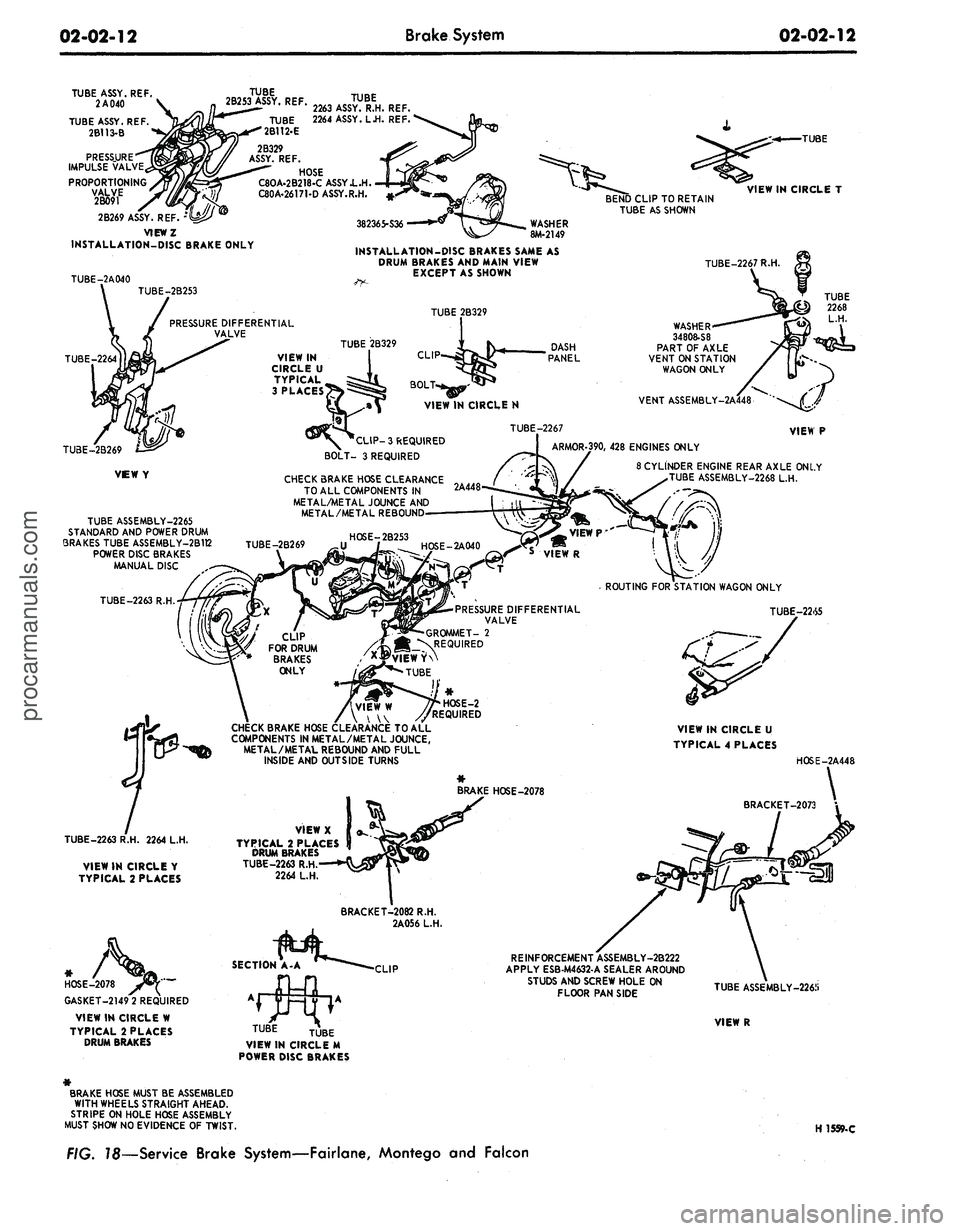
the brake cylinder Figs. 17 thru 21.
On
a
vehicle with
a
vacuum brake
booster,
be
sure
the
engine
is
stopped
and there
is no
vacuum
in the
booster
system before disconnecting
the hy-
draulic lines.
To disconnect the hose at a front
cylinder, loosen the tube fitting that
connects the opposite end of the hose
to the brake tube at a bracket on the
frame. Remove the horseshoe-type re-
taining clip from the hose and brack-
et, disengage the hose from the brack-
et, then unscrew the entire hose as-
sembly from the front wheel cylinder.
At a rear cylinder, unscrew the tubeprocarmanuals.com
Page 31 of 413
02-02-12
Brake System
02-02-12
TUBE ASSY. REF.
2 A 040
TUBE ASSY. REF.
2B113-B
PRESSURE
IMPULSE VALVE
PROPORTIONING
TUBE
>Y.
2B253 ASSY REF TUBE
/W W '
Kth#
2263 ASSY. R.H. REF.
TUBE
2B112-E
2264 ASSY. L.H. REF.
2B329
ASSY. REF.
HOSE
C8OA-2B218-C ASSY.L.H.
C80A-26171-D ASSY.R.H.
2B269 ASSY. REF.
VIEWZ
INSTALLATION-DISC BRAKE ONLY
BEND CLIP TO RETAIN
TUBE AS SHOWN
-TUBE
VIEW IN CIRCLE T
382365-S36
WASHER
8M-2149
TUBE-2A040
INSTALLATION-DISC BRAKES SAME AS
DRUM BRAKES AND MAIN VIEW
EXCEPT AS SHOWN
TUBE-2267 R.H.
TUBE-2B253
TUBE 2B329
PRESSURE DIFFERENTIAL
VALVE
TUBE 2B329
VIEW IN
CIRCLE U
TYPICAL ^,
CES^^
CLI
BOLT-
VIEW IN CIRCLE N
WASHER
34808-S8
PART OF AXLE
VENT ON STATION
WAGON ONLY
VENT ASSEMBLY
TUBE ASSEMBLY-2265
STANDARD AND POWER DRUM
3RAKES TUBE ASSEMBLY-2B1T2
POWER DISC BRAKES
MANUAL DISC
TUBE-2263 R.H.
3 REQUIRED
BOLT- 3 REQUIRED
CHECK BRAKE HOSE CLEARANCE „
TO ALL COMPONENTS IN
2A448"
METAL/METAL JOUNCE AND
METAL/METAL REBOUND-
TUBE-2267
ARMOR-390, 428 ENGINES ONLY
8 CYLINDER ENGINE REAR AXLE ONLY
TUBE ASSEMBLY-2268 L.H.
PRESSURE DIFFERENTIAL
VALVE
- GROMMET- 2
jl^REQUIRED
EWYN
TUBE
VIEW P
ROUTING FOR STATION WAGON ONLY
TUBE-22.S5
TUBE-2263 R.H. 2264 L.H.
VIEW IN CIRCLE Y
TYPICAL 2 PLACES
CHECK BRAKE HOSE CLEARANCE TO ALL
COMPONENTS IN METAL/METAL JOUNCE,
METAL/METAL REBOUND AND FULL
INSIDE AND OUTSIDE TURNS
VIEWX
TYPICAL 2 PLACES
DRUM BRAKES
TUBE-2263 R.H
2264 L.H.
VIEW IN CIRCLE U
TYPICAL 4 PLACES
HOSE-2A448
BRAKE HOSE-2078
GASKET-2149 2 REQUIRED
VIEW IN CIRCLE W
TYPICAL 2 PLACES
DRUM BRAKES
LIP
REINFORCEMENT ASSEMBLY-2B222
APPLY ESB-M4632-A SEALER AROUND
STUDS AND SCREW HOLE ON
FLOOR PAN SIDE
TUBE
TUBE ASSEMBLY-226J)
VIEW R
TUBE
VIEW IN CIRCLE M
POWER DISC BRAKES
BRAKE HOSE MUST BE ASSEMBLED
WITH WHEELS STRAIGHT AHEAD.
STRIPE ON HOLE HOSE ASSEMBLY
MUST SHOW NO EVIDENCE OF TWIST.
H 1559-C
—Service Brake
System—Fairlane,
Montego
and
Falconprocarmanuals.com
Page 43 of 413
02-02-24
Brake
System
02-02-24
proportioning valve to the fender
apron and remove the proportioning
valve.
Installation
1.
Position the proportioning valve
to the fender apron.
2.
Connect the two brake lines at
the proportioning valve. Do not tight-
en.
3.
Install the bolt retaining the pro-
portioning valve to the fender apron.
4.
Tighten the brake line tube nuts
at the proportioning valve to specifica-
tions.
5.
Bleed the brakes and centralize
pressure differential valve.
THUNDERBIRD AND
CONTINENTAL MARK III
Removal
Refer to Fig. 20.
1.
Disconnect the two hydraulic
brake lines at the master cylinder.
2.
Remove the two nuts retaining
the master cylinder to the booster and
remove the master cylinder for clear-
ance.
3.
Disconnect the two brake lines at
the proportioning valve.
4.
Remove the bolt and nut retain-
ing the proportioning valve to the
pressure differential valve bracket and
remove the proportioning valve assem-
bly.
Installation
1.
Transfer the bracket to the new
proportioning valve.
2.
Position the proportioning valve
assembly to the pressure differential
valve bracket.
3.
Connect the two brake lines to
the proportioning valve. Do not tight-
en.
4.
Install the bolt and nut retaining
the proportioning valve to the pressure
differential valve bracket.
5.
Tighten the two brake line tube
nuts at the proportioning valve to
specifications.
6. Position the master cylinder to
the booster and install the nuts retain-
ing the master cylinder to the booster.
7.
Connect the two brake lines at
the master cylinder and tighten the
tube nuts to specifications.
8. Bleed the brakes and centralize
the pressure differential valve.
LINCOLN CONTINENTAL
Removal
Refer to Fig. 21.
1.
Disconnect the two brake lines at
the proportioning valve.
2.
Loosen the bolt and nut on the
bracket retaining the proportioning
valve to the chassis.
3.
Remove the proportioning valve
from the bracket.
Installation
- 1. Position the proportioning valve
in the bracket and connect the two
brake lines. Do not tighten.
2.
Tighten the bolt and nut on the
bracket.
3.
Tighten the tube nuts on the
brake lines at the proportioning valve
to specifications.
4.
Bleed the brakes and centralize
the pressure differential valve.
PRESSURE METERING VALVE—
LINCOLN CONTINENTAL
REMOVAL
Refer to Fig. 21.
1.
Loosen the tube nuts connecting
the inlet and outlet tubes at the me-
tering valve, and remove the tubes.
2.
Remove the two screws retaining
the metering valve to the frame
crossmember, and remove the me-
tering valve. The metering valve is ser-
viced as an assembly only.
INSTALLATION
1.
Position the metering valve to
the frame crossmember, and install
the retaining screws.
2.
Connect the inlet and outlet
tubes to the metering valve, and tight-
en the tube nuts to specification.
BRAKE BOOSTER
REMOVAL
1.
Working from inside the\ vehicle
below the instrument panel, disconnect
the booster push rod from the brake
pedal assembly. To do this, proceed as
follows:
Disconnect the stop light switch
wires at the connector. Remove the
hairpin retainer. Slide the stop light
switch off from the brake pedal pin
just far enough for the switch outer
hole to clear the pin, and then remove
the switch from the pin and booster
push rod. Be careful not to damage
the switch during removal. Slide the
booster push rod and the nylon wash-
ers and bushing off the brake pedal
pin (Figs. 29 thru 33).
2.
Open the hood and remove the
master cylinder from the booster. Se-
cure it to one side without disturbing
the hydraulic lines. It is not necessary
to disconnect the brake lines, but care
should be taken that the brake lines
are not deformed. Permanent defor-
mation of brake lines can lead to tube
failure.
3.
Disconnect the manifold vacuum
hose or hoses from the booster unit.
4.
Remove the booster-to-dash
panel attaching nuts or bolts (Figs. 29
thru 33). Remove the booster and
bracket assembly from the dash panel,
sliding the push rod link out from the
engine side of the dash panel.
5.
On Fairlane, Montego, and Fal-
con models, remove the push rod link
boot from the dash panel.
INSTALLATION
1.
On Fairlane, Montego and Fal-
con models, install the push rod link
boot in the hole in the dash panel as
shown in Fig. 23. Install the four
spacers on the mounting studs.
2.
Mount the booster and bracket
assembly to the dash panel by insert-
ing the push rod or push rod link in
through the hole and boot in the dash
panel. Install the bracket-to-dash
panel attaching lock nuts or bolts
(Figs.
29 thru 33).
3.
Connect the manifold vacuum
hose or hoses to the booster.
4.
Before installing the master cyl-
inder, check the distance from the
outer end of the booster assembly
push rod to master cylinder surface.
Turn the screw in or out to obtain the
specified length. Refer to Part 2-1,
Section 2, Power Brake Master Cylin-
der Push Rod Adjustment. Install the
master cylinder and torque the attach-
ing nuts to specifications.
5.
Working from inside the vehicle
below the instrument panel, connect
the booster push rod link to the brake
pedal assembly. To do this, proceed as
follows:
Install the inner nylon washer, the
booster push rod, and the bushing on
the brake pedal pin. Position the
switch so that it straddles the push
rod with the switch slot on the pedal
pin and the switch outer hole justprocarmanuals.com
Page 44 of 413
02-02-25
Brake System
02-02-25
clearing the pin. Slide the switch com-
pletely onto the pin, and install the
nylon washer as shown in Figs. 29
thru 33. Be careful not to bend or de-
form the switch. Secure these parts to
the pin with the hairpin retainer. Con-
nect the stop light switch wires to the
connector, and install the wires in the
retaining clip.
BRAKE PEDAL
FORD, MERCURY
AND METEOR
Removal
1.
Disconnect the stop light switch
wires at the connector.
2.
Remove the hairpin retainer.
Slide the stop light switch off the
brake pedal pin just far enough for
the switch outer hole to clear the pin,
and then lift the switch straight up-
ward from the pin. Be careful not to
damage the switch during removal.
Slide the master cylinder or booster
push rod and the nylon washers and
bushing off the brake pedal pin (Figs.
26 and 29).
3.
Remove the hairpin type retainer
and washer from the brake pedal
shaft, then remove the shaft, the brake
pedal and the bushings from the pedal
support bracket.
Installation
1.
Apply a coating of SAE 10 En-
gine oil to the bushings and locate
bushings in their proper places on the
pedal assembly and pedal support
bracket (Figs. 26 and 29).
2.
Position the brake pedal assem-
bly to the support bracket, then install
the pedal shaft through the support
bracket and brake pedal assembly. In-
stall the retainer.
3.
Install the inner nylon washer,
the master cylinder or booster push
rod, and the bushing on the brake
pedal pin. Position the switch so that
it straddles the push rod with the
switch slot on the pedal pin and the
switch outer hole just clearing the pin.
Slide the switch completely onto the
pin, and install the nylon washer as
shown in Figs. 26 and 29. Be careful
not to bend or deform the switch. Se-
cure these parts to the pin with the
hairpin retainer.
4.
Connect the stop light switch
wires to the connector, and install the
wires in the retaining clip.
5.
Check the Brake Pedal Free
Height and Travel Measurements,
Part 2-1, Section 1.
FAIRLANE, MONTEGO AND
FALCON—MANUAL-SHIFT
TRANSMISSION
Removal
1.
Remove the clutch pedal assist
spring.
2.
Disconnect the clutch pedal-
to-equalizer rod at the clutch pedal by
removing the retainer and bushing.
3.
Disconnect the stop light switch
wires at the connector.
4.
Remove the switch retainer, and
slide the stop light switch off the
brake pedal pin just far enough for
the switch outer hole to clear the pin.
Then lower the switch away from the
pin.
5. Slide the master cylinder or
booster push rod and the nylon wash-
ers and bushing off from the brake
pedal pin (Figs. 27 and 30).
6. Remove the self-locking pin and
washer from the clutch and brake
pedal shaft, then remove the clutch
pedal and shaft assembly, the brake
pedal assembly, and the bushings from
the pedal support bracket (Figs. 27
and 30).
Installation
1.
Apply a coating of SAE 10 en-
gine oil to the bushings and locate all
bushings in their proper places on the
clutch and brake pedal assemblies.
2.
Position the brake pedal to the
support bracket, then install the clutch
pedal and shaft assembly through the
support bracket and brake pedal as-
sembly. Install the spring clip (Figs.
27 and 30).
3.
Install the clutch pedal assist
spring.
4.
Connect the clutch pedal-
to-equalizer rod to the clutch pedal
assembly with the bushing and the
spring clip retainer. Apply SAE 10
engine oil to the bushing.
5.
Install the inner nylon washer,
the master cylinder or booster push
rod, and the bushing on the brake
pedal pin. Position the switch so that
it straddles the push rod with the
switch slot on the pedal pin and the
switch outer hole just clearing the pin.
Slide the switch completely onto the
pin, and install the outer nylon washer
as shown in Figs. 27 and 30. Secure
these parts to the pin with the
self-
locking pin.
6. Connect the stop light switch
wires to the connector, and install the
wires to the retaining clip.
7.
Adjust the clutch pedal free play
(Group 5) to specification, if required.
8. Check the Brake Pedal Free
Height and Travel Measurements
(Part 2-1, Section 1).
MUSTANG AND COUGAR—
MANUAL-SHIFT
TRANSMISSION
Removal
1.
Disconnect the battery ground
cable from the battery.
2.
Remove the steering column.
Refer to Part 3-4, Section 2 for pro-
cedure.
3.
On non-power brakes, remove
the two cap screws retaining the mas-
ter cylinder to the dash panel and re-
move the two cap screws retaining the
brake pedal support bracket to the
dash panel. On power brakes remove
the two cap screws retaining the
booster to the dash panel.
4.
Working inside the vehicle, se-
cure the clutch pedal against the
bumper stop with a small C-clamp as
shown in Figs. 28 and 31.
5.
Disconnect the clutch pedal-
to-equalizer rod at the clutch pedal by
removing the retainer and bushing.
6. Disconnect the stop light switch
wires at the connector.
7.
Remove the switch retainer and
slide the stop light switch off the
brake pedal pin just far enough for
the switch outer hole to clear the pin.
Then lower the switch away from the
pin.
Remove the master cylinder or
booster push rod, bushing and nylon
washer from the brake pedal pin.
8. Remove the screw retaining the
pedal support bracket to the top inner
cowl bracket (Figs. 28 and 31).
9. Remove the two sheet metal
screws retaining the pedal support
bracket to the dash panel. On power
brakes remove the nuts from the
brake booster studs.
10.
Remove the two screws retain-
ing the pedal support bracket to the
upper cowl brace and lower the pedal
support bracket away from the steer-
ing column studs.
11.
Remove the pedal support
bracket assembly from the vehicle.
12.
Position the pedal and support
bracket assembly in a vise.
13.
Remove the C-clamp to release
the clutch pedal from its bumper stop
and pivot the pedal away from the
bumper.procarmanuals.com