dimensions FORD MUSTANG 1969 Volume One Chassis
[x] Cancel search | Manufacturer: FORD, Model Year: 1969, Model line: MUSTANG, Model: FORD MUSTANG 1969Pages: 413, PDF Size: 75.81 MB
Page 15 of 413
02-01-04
Brakes
02-01-04
ft-lb breakaway torque.
The
breaka-
way torque
is the
torque required
to
turn
the
rear wheels
the
direction
of
forward rotation with
a
torque wrench
and tool shown
in Fig. 5. The
torque
measurement must
be
made relative
to
the center line
of the
wheel.
4.
Release
the
parking brake,
and
check
to
make sure that
the
brake
shoes return
to the
fully released posi-
tion.
5.
Depress
the
parking brake pedal
to
the
third notch. Under normal
con-
ditions, this will hold
the
vehicle satis-
factorily.
6. Release
the
parking brake again,
and check
as in
step
4.
7.
If the
rear brakes
do not
fully
release, check
the
cables
for
kinks
or
binds.
Free
the
cables
as
required.
8. Lower
the
vehicle. Remove
the
torque wrench
and
tool. Install
the
wheel attaching nuts
and
torque them
to specification. Install
the
wheel
cover.
RETAINER-*^ REAR WHEEL
(CABLE ASSEMBLY
EQUALIZER
NUT
PARKING
BRAKE CABLE
AND CONDUIT
ASSEMBLY-2853
SPRING-2A651
SPRING SEAT-2A616
JAM NUT
H1631-A
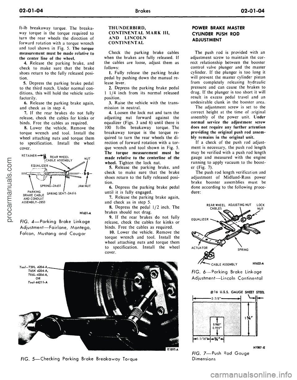
FIG. 4—Parking Brake Linkage
Adjustment—Fairlane, Montego,
Falcon,
Mustang
and
Cougar
THUNDERBIRD,
CONTINENTAL MARK
III,
AND LINCOLN
CONTINENTAL
Check
the
parking brake cables
when
the
brakes
are
fully released.
If
the cables
are
loose, adjust them
as
follows:
1.
Fully release
the
parking brake
pedal
by
pushing down
the
manual
re-
lease lever.
2.
Depress
the
parking brake pedal
1
1/4
inch from
its
normal released
position.
3.
Raise
the
vehicle with
the
trans-
mission
in
neutral.
4.
Loosen
the
lock
nut and
turn
the
adjusting
nut
forward against
the
equalizer (Figs.
3 and 6)
until there
is
100 ft-lbs breakaway torque.
The
breakaway torque
is the
torque
re-
quired
to
turn
the
rear wheels
the di-
rection
of
forward rotation with
a tor-
que wrench
and
tool shown
in Fig. 5.
The torque measurement must
be
made relative
to the
centerline
of the
wheel. Tighten
the
lock
nut.
5.
Release
the
parking brake,
and
check
to
make sure that
the
brake
shoes return
to the
fully released posi-
tion.
6. Depress
the
parking brake pedal
until
it is
fully engaged.
7.
Release
the
parking brake again,
and check
as in
step
5.
8. Depress
the
pedal
1/2
inch.
The
brakes should
not
drag.
9.
If the
rear brakes
do not
fully
release, check
the
cables
for
kinks
or
binds.
Free
the
cables
as
required.
10.
Lower
the
vehicle. Remove
the
torque wrench
and
tool. Install
the
wheel attaching nuts
and
torque them
to specification. Install
the
wheel
cover.
Tool-T59L
4204-A,
T65K
4204-A,
T66L-4204-A,
OR
Tool-4421UA
E1897-A
POWER BRAKE MASTER
CYLINDER PUSH
ROD
ADJUSTMENT
The push
rod is
provided with
an
adjustment screw
to
maintain
the cor-
rect relationship between
the
booster
control valve plunger
and the
master
cylinder.
If the
plunger
is too
long
it
will prevent
the
master cylinder piston
from completely releasing hydraulic
pressure
and can
cause
the
brakes
to
drag.
If the
plunger
is too
short
it
will
result
in
excess pedal travel
and an
undesirable clunk
in the
booster area.
The adjustment screw
is set to the
correct height
at the
time
of
original
assembly
of the
power unit. Under
normal service
the
adjustment screw
does
not
require
any
further attention
providing
the
original push
rod
assem-
bly remains
in the
original unit.
If
a
check
of the
push
rod
adjust-
ment
is
necessary,
the
push
rod
length
may
be
verified with
a
push
rod
length
gauge
and
measured with
the
engine
running
to
apply vacuum
to the
boost-
er (Fig.
7).
The push
rod
length verification
and
adjustment
of
Midland-Ross power
brake booster assemblies must
be
done according
to the
following proce-
dure:
REAR WHEEL ADJUSTING NUT
CABLES
EQUALIZER
SPRING
CABLE ASSEMBLY H1632-A
FIG. 6—Parking Brake Linkage
Adjustment—Lincoln Continental
FIG. 5—Checking Parking Brake Breakaway Torque
#16
U.J
\
0.980"
0.995"
FIG. 7—Push
Dimensions
>.S. GAUGE SHEET
i
1
STEEL
H1087-E
Rod Gaugeprocarmanuals.com
Page 18 of 413
02-01-07
Brakes
02-01-07
CENTRALIZING THE
PRESSURE DIFFERENTIAL
VALVE
After a failure of the primary (front
brake) or secondary (rear brake) sys-
tem has been repaired and bled, the
dual-brake warning light will usually
continue to be illuminated due to the
pressure differential valve remaining in
the off-center position.
To centralize the pressure differen-
tial valve and turn off the warning
light after a repair operation, a pres-
sure differential or unbalance condi-
tion must be created in the opposite
brake system from the one that was
repaired or bled last.
1.
Turn the ignition switch to the
ACC or ON position. Loosen the dif-
ferential valve assembly brake tube
nut at the outlet port on the opposite
side of the brake system that was
wheel balanced, repaired and/or bled
last. Depress the brake pedal slowly to
build line pressure until the pressure
differential valve is moved to a cen-
tralized position and the brake warn-
ing light goes out; then, immediately
tighten the outlet port tube nut.
2.
Check the fluid level in the mas-
ter cylinder reservoirs and fill them to
within 1/4 inch of the top with the
specified brake fluid, if necessary.
3.
Turn the ignition switch to the
OFF position.
4.
Before driving the vehicle, check
the operation of the brakes and be
sure that a firm pedal is obtained.
CLEANING AND INSPECTION
DISC BRAKES
1.
Remove the wheel and tire and
the shoe and lining assemblies as out-
lined in Part 2-2, Section 2.
2.
On all models except Lincoln
Continental, make thickness measure-
ments with a micrometer across the
thinnest section of the shoe and lining.
If the assembly has worn to a thick-
ness of 0.230-inch (shoe and lining to-
gether) or 0.030-inch (lining material
only) at any one of three measuring
locations or if there is more than
0.125 taper from end to end or if lin-
ing shows evidence of brake fluid con-
tamination, replace all (4) shoe and
lining assemblies on both front wheels.
On Lincoln Continental brakes
make three thickness measurements
with a micrometer across the middle
section of the shoe and lining. Take
one reading at each side and one in
the center. If the assembly has worn
to a thickness of 0.231 inch (shoe and
lining together) or 0.066 inch (lining
material only) at any one of the three
measuring locations, replace all (4)
shoe and lining assemblies on both
front wheels.
3.
Check the caliper to spindle at-
taching bolts torque. Torque them to
specification, if required.
4.
To check rotor runout, first
eliminate the wheel bearing end play
by tightening the adjusting nut. After
tightening the nut, check to see that
the rotor can still be rotated.
5.
Clamp a dial indicator to the
caliper housing so that the stylus con-
tact the rotor at a point approximate-
ly 1 inch from the outer edge. Rotate
the rotor and take an indicator read-
ing. If the reading exceeds 0.003 inch
total lateral runout on the indicator,
replace or resurface the disc brake
rotor. The following requirement must
be met when resurfacing disc brake
rotors:
Rotunda Disc Brake Attachment
FRE-2249-2 is the only approved tool
to be used to refinish the disc brake
rotors.
The step-by-step resurfacing
procedure provided with the tool must
be adhered to.
The finished braking surface of the
rotor must be flat and parallel within
0.0007 inch; lateral runout must not
exceed 0.003 inch total indicator
reading, braking surface are to be 80/15
micro inches.
On all models except Lincoln Con-
tinental the minimum limiting dimen-
sion from the inboard bearing cup to
the inboard rotor face and the mini-
mum rotor thickness dimension, must
be observed when removing material
from the rotor braking surfaces. A
ball and gage bar (Rotunda Kit FRE
70160) is to be used when checking
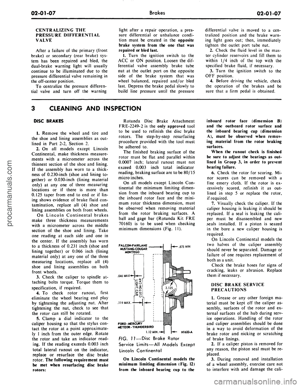
minimum dimensions (Fig. 11).
FALCON-FAIRLANE
MUSTANG-COUGAR
MONTEGO
.046 MAX-**
.119
MAX.
FORD-MERCURY
METEOR - THUNDERBIRD
875
MIN
H1633-A
1.12
MIN.-^
??
— Disc Brake Rotor
Service Limits—All Models Except
Lincoln Continental
On Lincoln Continental models the
minimum limiting dimension (Fig. 12)
from the inboard bearing cup to the
inboard rotor face (dimension B)
and the outboard rotor surface and
the inboard bearing cup (dimension
A),
must be observed when remov-
ing material from the rotor braking
surfaces.
When the runout check is finished
be sure to adjust the bearings as out-
lined in Group 3, in order to prevent
bearing failure.
6. Check the rotor for scoring. Mi-
nor scores can be removed with a
fine emery cloth. If the rotor is ex-
cessively scored, refinish it as out-
lined in step 5 or replace the rotor,
if required.
7.
Visually check the caliper. If the
caliper housing is leaking it should be
replaced. If a seal is leaking the cali-
per must be disassembled and new
.seals installed. If a piston is seazed
in the bore a new caliper housing is
required.
On Lincoln Continental models the
two halves of the caliper assembly
should never be separated. Damage or
failure of one requires replacement of
both as a unit.
Check the brake hoses for signs of
cracking, leaks or abrasion. Replace
them if necessary.
DISC BRAKE SERVICE
PRECAUTIONS
1.
Grease or any other foreign ma-
terial must be kept off the caliper as-
sembly, surfaces of the rotor and ex-
ternal surfaces of the hub during serv-
ice operations. Handling of the rotor
and caliper assemblies should be done
in a way to avoid deformation of the
brake rotor and nicking or scratching
of brake linings.
2.
If a caliper piston is removed for
any reason, the piston seal must be re-
placed.
3.
During removal and installation
of a wheel assembly, exercise care not
to interfere with and damage the cali-procarmanuals.com
Page 58 of 413
02-02-39
Brake System
02-02-39
MAJOR REPAIR OPERATIONS
BRAKE DRUM REFINISHING
Minor scores on a brake drum can
be removed with sandpaper. A drum
that is excessively scored or shows a
total indicator runout of over 0.007
inch should be turned down. Remove
only enough stock to eliminate the
scores and true up the drum. The refi-
nished diameter must not exceed 0.060
inch oversize.
Check the inside diameter of the
brake drum with a brake drum mi-
crometer (Tool FRE-14^1).
If the drum diameter is less than
0.030 inch oversize after refinishing^
standard lining may be installed. If
the drum diameter is 0.030—0.060
inch oversize after refinishing, oversize
lining must be installed.
After a drum is turned down, wipe
the refinished surface with a cloth
soaked in clean denatured alcohol. If
one drum is turned down, the opposite
drum on the same axle should also be
cut down to the same size.
ROTOR REFINISHING
Rotunda Disc Brake Attachment,
FRE-2249-2, is the only recommended
tool to refinish the disc brake rotors.
The step-by-step resurfacing procedure
provided with the tool must be ad-
hered to.
The finished braking surfaces of the
rotor must be flat and parallel within
0.0007 inch; lateral runout must not
exceed 0.003 inch total indicator read-
ing, and the surface finish of the brak-
ing surfaces are to be 80/15 micro
inches. The minimum limiting dimen-
sions (Figs. 11 and 12, Part 2-1) from
the inboard bearing cup to the out-
board rotor face and from the inboard
bearing cup to the inboard rotor face
must be observed when removing ma-
terial from the rotor braking surfaces.
On all models except Lincoln Con-
tinental, the limiting dimensions are to
be measured with a ball and gage bar
(Rotunda Kit FRE-70160).
BRAKE SHOE RELINING
Brake linings that are worn to with-
in 1/32 inch of the rivet head or are
less than 0.030 inch thick (bonded lin-
ing) or have been contaminated with
brake fluid, grease or oil must be re-
placed. Failure to replace worn linings
will result in a scored drum. When it
is necessary to replace linings, they
must also be replaced on the wheel on
the opposite side of the vehicle.
Inspect brake shoes for distortion,
cracks, or looseness. If this condition
exists,
the shoe must be discarded. Do
not attempt to repair a defective brake
shoe.
1.
Wash the brake shoes thoroughly
in a clean solvent. Remove all burrs
or rough spots from the shoes.
2.
Check the inside diameter of the
brake drum with a brake drum mi-
crometer (tool FRE-1431). If the di-
ameter is less than 0.030 inches over-
size,
standard lining may be installed.
If the diameter is 0.030—0.060 inches
oversize, oversize lining should be in-
stalled.
3.
Position the new lining on the
shoe.
Starting in the center, insert and
secure the rivets, working alternately
towards each end. Replacement lin-
ings are ground and no further grind-
ing is required.
4.
Check the clearance between the
shoe and lining. The lining must seat
tightly against the shoe with not more
than 0.008 inch clearance between any
two rivets.
RETAINER - 2B245
DUAL MASTER CYLINDER
DISASSEMBLY
1.
Clean the outside of the master
cylinder and remove the filler cover
and diaphragm. Pour out any brake
fluid that remains in the cylinder. Dis-
card the old brake fluid.
2.*
Remove the secondary piston
stop bolt from the bottom of the cyl-
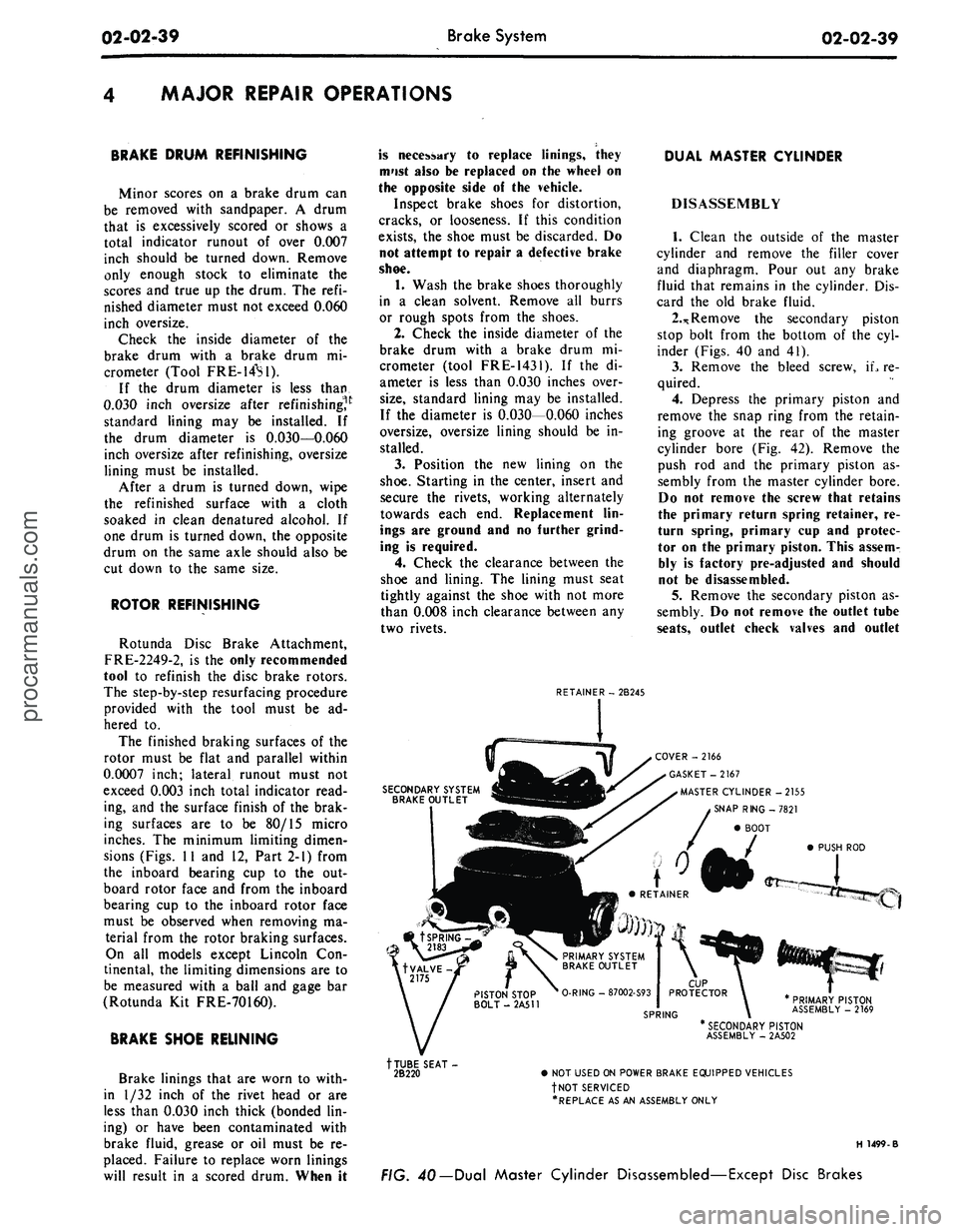
inder (Figs. 40 and 41).
3.
Remove the bleed screw, iL re-
quired.
4.
Depress the primary piston and
remove the snap ring from the retain-
ing groove at the rear of the master
cylinder bore (Fig. 42). Remove the
push rod and the primary piston as-
sembly from the master cylinder bore.
Do not remove the screw that retains
the primary return spring retainer, re-
turn spring, primary cup and protec-
tor on the primary piston. This assem-
bly is factory pre-adjusted and should
not be disassembled.
5.
Remove the secondary piston as-
sembly. Do not remove the outlet tube
seats,
outlet check valves and outlet
SECONDARY SYSTEM
BRAKE OUTLET
COVER -2166
GASKET-2167
MASTER CYLINDER -2155
SNAP RING -7821
BOOT
PUSH ROD
PRIMARY PISTON
ASSEMBLY - 2169
tTUBE SEAT-
2B220
* SECONDARY PISTON
ASSEMBLY - 2A502
• NOT USED ON POWER BRAKE EQUIPPED VEHICLES
fNOT SERVICED
•REPLACE AS AN ASSEMBLY ONLY
H 1499-B
FIG. 40— Dual Master Cylinder Disassembled—Except Disc Brakesprocarmanuals.com
Page 62 of 413
02-03-01
Specifications
02-03-01
PART
2-3
Specifications
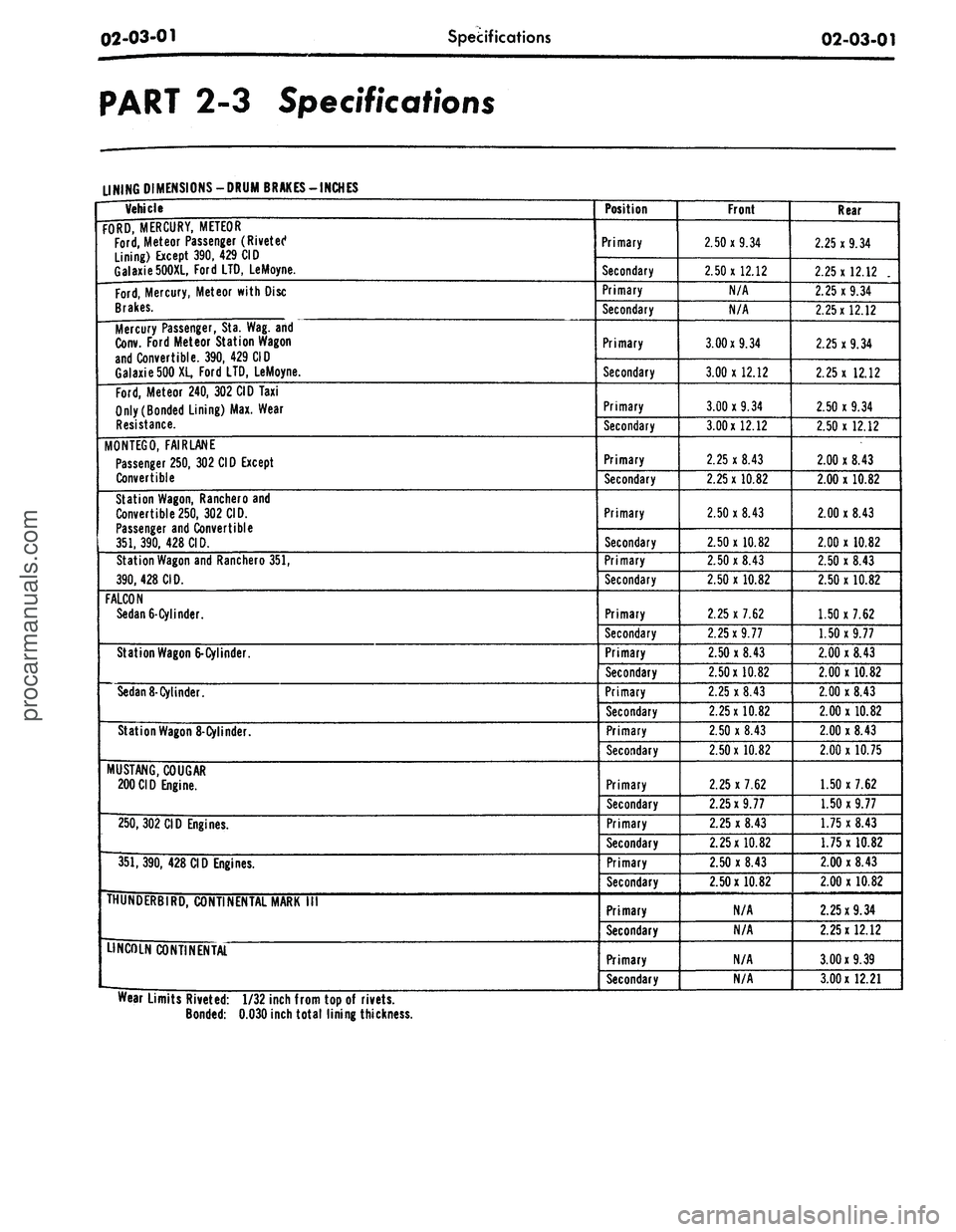
LINING
DIMENSIONS-DRUM
BRAKES-INCHES
Vehicle
FORD, MERCURY, METEOR
Ford,
Meteor Passenger (Rivetet1
Lining) Except 390, 429 CID
Galaxie500XL, Ford LTD, LeMoyne.
Ford,
Mercury, Meteor with Disc
Brakes.
Mercury Passenger, Sta. Wag. and
Conv. Ford Meteor Station Wagon
and Convertible. 390, 429 CID
Galaxie500XL, Ford LTD, LeMoyne.
Ford,
Meteor 240, 302 CID Taxi
Only (Bonded Lining) Max. Wear
Resistance.
MONTEGO,
FAIR LANE
Passenger 250, 302 CID Except
Convertible
Station Wagon, Ranchero and
Convertible250, 302 CID.
Passenger and Convertible
351,390, 428 CID.
Station Wagon and Ranchero 351,
390,
428 CID.
FALCON
Sedan
6-Cylinder.
Station Wagon
6-Cylinder.
Sedan
8- Cylinder.
Station Wagon
8-Cylinder.
MUSTANG, COUGAR
200CID Engine.
250,
302 CID Engines.
351,390, 428 CID Engines.
IHUNDERBIRD, CONTINENTAL MARK
III
LINCOLN CONTINENTAL
Position
Primary
Secondary
Primary
Secondary
Primary
Secondary
Primary
Secondary
Primary
Secondary
Primary
Secondary
Primary
Secondary
Primary
Secondary
Primary
Secondary
Primary
Secondary
Primary
Secondary
Primary
Secondary
Primary
Secondary
Primary
Secondary
Primary
Secondary
Primary
Secondary
Front
2.50x9.34
2.50x12.12
N/A
N/A
3.00x9.34
3.00x12.12
3.00x9.34
3.00x12.12
2.25 x 8.43
2.25x10.82
2.50x8.43
2.50x10.82
2.50x8.43
2.50 x 10.82
2.25 x 7.62
2.25x9.77
2.50 x 8.43
2.50x10.82
2.25 x 8.43
2.25x10.82
2.50 x 8.43
2.50x10.82
2.25 x 7.62
2.25x9.77
2.25 x 8.43
2.25x10.82
2.50 x 8.43
2.50x10.82
N/A
N/A
N/A
N/A
Rear
2.25x9.34
2.25x12.12
.
2.25x9.34
2.25x12.12
2.25x9.34
2.25 x 12.12
2.50 x 9.34
2.50x12.12
2.00 x 8.43
2.00 x 10.82
2.00x8.43
2.00 x 10.82
2.50 x 8.43
2.50 x 10.82
1.50 x 7.62
1.50x9.77
2.00 x 8.43
2.00 x 10.82
2.00 x 8.43
2.00x10.82
2.00x8.43
2.00 x 10.75
1.50 x 7.62
1.50 x 9.77
1.75 x 8.43
1.75x10.82
2.00 x 8.43
2.00 x 10.82
2.25x9.34
2.25x12.12
3.00x9.39
3.00
x
12.21
Wear Limits Riveted: 1/32 inch from top of rivets.
Bonded:
0.030
inch total lining thicknessprocarmanuals.com
Page 63 of 413
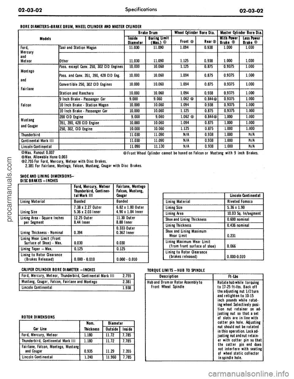
02-03-02
Specifications
02-03-02
BORE DIAMETERS-BRAKE DRUM, WHEEL CYLINDER AND MASTER
Models
Ford,
Mercury
and
Meteor
Mont ego
and
Fairlane
Falcon
Mustang
and Cougar
Thunderbird
Continental Mark
III
Lincoln Continental
Taxi and Station Wagon
Other
Pass, except Conv. 250, 302 CID Engines
Pass, and Conv. 351, 390, 428 CID Eng.
Convertible 250, 302 CID Engines
Station and Ranchero
9 Inch Brake
-
Passenger Car
10 Inch Brake
•
Station Wagon
10 Inch Brake
•
Passenger Car
200 CID Engine
351,
390, 428 CID Engine
250,
302, CID Engine
CYLINDER
Brake Drum
Inside
Diameter
11.030
11.030
10.000
10.000
10.000
10.000
9.000
10.000
10.000
9.000
10.000
10.000
11.030
11.030
11.090
Boring Umit
(Max.)
®
11.090
11.090
10.060
10.060
10.060
10.060
9.060
10.060
10.060
9.060
10.060
10.060
11.090
11.090
11.130
Wheel Cylinder Bore Dia.
Front
0
1.094
L_ U25
1.125
1.094
1.094
1.094
1.062
0
1.094
1.125
1.062
®
1.094
1.125
N/A
N/A
N/A
Rear
®
0.938
0.938
0.875
0.875
0.875
0.938
0.844®
0.938
0.875
0.844®
0.875
0.875
0.938
0.938
0.938
Master Cylinder Bore Dia.
With Power
Brake
®
1.000
1.000
0.9375
0.9375
0.9375
0.9375
0.9375
0.9375
0.9375
1.000
1.000
1.000
1.000
1.000
1.000
Less Power
Brake
®
1.000
1.000
1.000
1.000
1.000
1.000
1.000
1.000
1.000
1.000
1.000
1.000
N/A
N/A
N/A
©Max. Runout
0.007
(DMax. Allowable Hone
0.003
CD2.755 For
Ford,
Mercury, Meteor with Disc Brakes.
2.381 For Fairlane, Montego, Falcon, Mustang, Cougar with Disc Brakes.
SHOE AND LINING DIMENSIONS-
DISC BRAKES-INCHES
® Front Wheel Cylinder cannot be honed on Falcon or Mustang with
9
inch Brakes.
Lining Material
Lining Size
Lining Area
-
Square Inches
per Segment
Lining Thickness • Nominal
Lining Wear Limit (Front
Surface
of
Shoe)
•
Max.
Lining Taper -Max.
Lining to Rotor Clearance
(Brakes Released)
Ford,
Mercury, Meteor
Thunderbird, Continen-
tal Mark
III
Bonded
7.38x2.27
Outer
5.36x2.03
Inner
12.25 Outer
8.44 Inner
0.394
0.030
0.125
0.000-0.010
Fairlane, Montego
Falcon,
Mustang,
Cougar
Bonded
6.82 x 1.80 Outer
4.90x1.84 Inner
11.30 Outer
8.80 Inner
0.333
Outer
0.362
Inner
0.030
0.125
0.000
• 0.010
Lining Material
Lining Size
Lining Area
Shoe and Lining Thickness
Lining Thickness
Shoe and Lining Maximum
Wear Limit
Lining Maximum Wear Limit
(from front surface
of
shoe)
Lining to Rotor Clearance
(brakes released)
Lincoln Continental
Riveted Fomoco
5.36x1.90
10.03 Sq. In/segment
0.600
nominal
0.436
nominal
0.231
0.066
0.000-0.010
CALIPER CYLINDER BORE DIAMETER -INCHES
TORQUE LIMITS-HUB TO SPINDLE
Ford,
Mercury, Meteor, Thunderbird, Continental Mark
2.755
Mustang, Cougar, Falcon, Fairlane and Montego
2.381
Lincoln Continental
1.938
ROTOR DIMENSIONS
Car Line
Ford,
Mercury, Meteor
Thunderbird, Continental Mark
III
Fairlane, Falcon, Montego, Mustang
and Cougar
Lincoln Continental
Norn.
Thickness
1.180
1.180
0.935
1.240
Diameter
Outside
11.72
11.72
11.29
11.960
Inside
7.785
7.785
7.355
7.785
Description
Hub and Drum or Rotor Assembly to
Front Wheel Spindle
Ft-Lbs
Rotate
hub
while torquing
to 17-25 ft-lbs. Backoff
the adjusting nut 1/2 turn
and retighten to 10-15
inch pounds while rotat-
ing wheel Selectively
posi-
tion
nut
retainer
on ad-
justing nut
so
that a set
of slots are in line with
cotter pin hole. Adjusting
nut should not be rotated
in this operation. Lock
ad-
justing nut and nut retain-
er with cotter pin so that
the cotter
pin end
does
not interfere with seating
of wheel static collector
in spindle hole.procarmanuals.com
Page 85 of 413
03-02-09
Suspension
03-02-09
WOOD BLOCK
F
1287-A
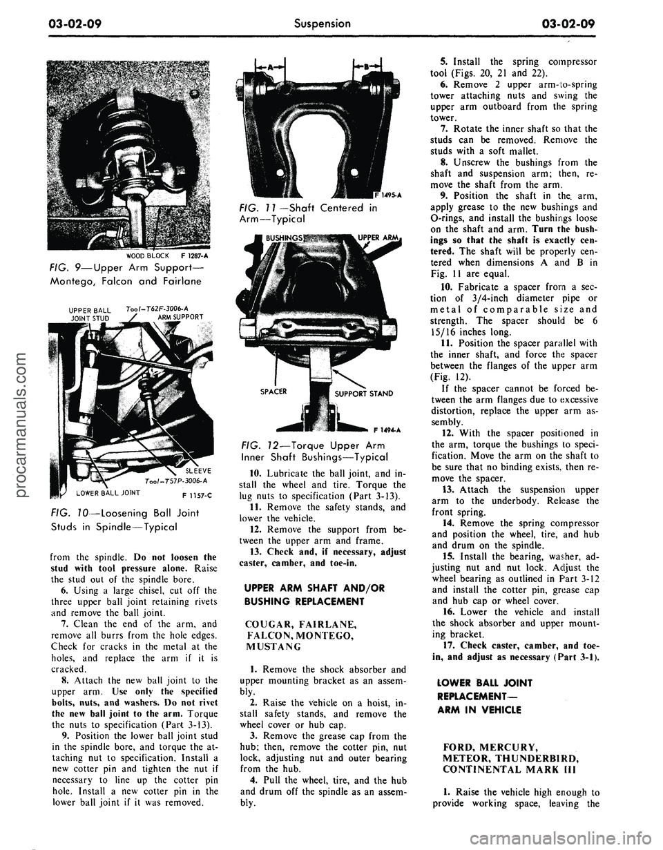
FIG. 9—Upper
Arm
Support—
Montego, Falcon
and
Fairlane
Tool-T62F-3006-A
ARM SUPPORT
LOWER BALL JOINT
SLEEVE
Too/-T57P-3006-A
F 1157-C
FIG. TO—Loosening Ball Joint
Studs
in
Spindle—Typical
from
the
spindle.
Do not
loosen
the
stud with tool pressure alone. Raise
the stud
out of the
spindle bore.
6. Using
a
large chisel,
cut off the
three upper ball joint retaining rivets
and remove
the
ball joint.
7.
Clean
the end of the arm, and
remove
all
burrs from
the
hole edges.
Check
for
cracks
in the
metal
at the
holes,
and
replace
the arm if it is
cracked.
8. Attach
the new
ball joint
to the
upper
arm. Use
only
the
specified
bolts,
nuts,
and
washers.
Do not
rivet
the
new
ball joint
to the
arm. Torque
the nuts
to
specification (Part 3-13).
9. Position
the
lower ball joint stud
in
the
spindle bore,
and
torque
the at-
taching
nut to
specification. Install
a
new cotter
pin and
tighten
the nut if
necessary
to
line
up the
cotter
pin
hole.
Install
a new
cotter
pin in the
lower ball joint
if it was
removed.
1495-A
FIG. 11 —Shaft Centered
in
Arm—Typical
F 1494- A
FIG. 12—Torque Upper
Arm
Inner Shaft Bushings—Typical
10.
Lubricate
the
ball joint,
and in-
stall
the
wheel
and
tire. Torque
the
lug nuts
to
specification (Part 3-13).
11.
Remove
the
safety stands,
and
lower
the
vehicle.
12.
Remove
the
support from
be-
tween
the
upper
arm and
frame.
13.
Check
and, if
necessary, adjust
caster, camber,
and
toe-in.
UPPER ARM SHAFT AND/OR
BUSHING REPLACEMENT
COUGAR, FAIRLANE,
FALCON, MONTEGO,
MUSTANG
1.
Remove
the
shock absorber
and
upper mounting bracket
as an
assem-
bly.
2.
Raise
the
vehicle
on a
hoist,
in-
stall safety stands,
and
remove
the
wheel cover
or hub cap.
3.
Remove
the
grease
cap
from
the
hub;
then, remove
the
cotter
pin, nut
lock, adjusting
nut and
outer bearing
from
the hub.
4.
Pull
the
wheel, tire,
and the hub
and drum
off the
spindle
as an
assem-
bly.
5.
Install
the
spring compressor
tool (Figs.
20, 21 and 22).
6. Remove
2
upper arm-to-spring
tower attaching nuts
and
swing
the
upper
arm
outboard from
the
spring
tower.
7.
Rotate
the
inner shaft
so
that
the
studs
can be
removed. Remove
the
studs with
a
soft mallet.
8. Unscrew
the
bushings from
the
shaft
and
suspension
arm;
then,
re-
move
the
shaft from
the arm.
9. Position
the
shaft
in the. arm,
apply grease
to the new
bushings
and
O-rings,
and
install
the
bushings loose
on
the
shaft
and
arm. Turn
the
bush-
ings
so
that
the
shaft
is
exactly
cen-
tered.
The
shaft will
be
properly
cen-
tered when dimensions
A and B in
Fig.
11 are
equal.
10.
Fabricate
a
spacer from
a sec-
tion
of
3/4-inch diameter pipe
or
metal
of
comparable size
and
strength.
The
spacer should
be 6
15/16 inches long.
11.
Position
the
spacer parallel with
the inner shaft,
and
force
the
spacer
between
the
flanges
of the
upper
arm
(Fig.
12).
If
the
spacer cannot
be
forced
be-
tween
the arm
flanges due
to
excessive
distortion, replace
the
upper
arm as-
sembly.
12.
With
the
spacer positioned
in
the
arm,
torque
the
bushings
to
speci-
fication. Move
the arm on the
shaft
to
be sure that
no
binding exists, then
re-
move
the
spacer.
13.
Attach
the
suspension upper
arm
to the
underbody. Release
the
front spring.
14.
Remove
the
spring compressor
and position
the
wheel, tire,
and hub
and drum
on the
spindle.
15.
Install
the
bearing, washer,
ad-
justing
nut and nut
lock. Adjust
the
wheel bearing
as
outlined
in
Part
3-12
and install
the
cotter
pin,
grease
cap
and
hub cap or
wheel cover.
16.
Lower
the
vehicle
and
install
the shock absorber
and
upper mount-
ing bracket.
17.
Check caster, camber,
and toe-
in,
and
adjust
as
necessary (Part 3-1).
LOWER BALL JOINT
REPLACEMENT-
ARM
IN
VEHICLE
FORD, MERCURY,
METEOR, THUNDERBIRD,
CONTINENTAL MARK
III
1.
Raise
the
vehicle high enough
to
provide working space, leaving
theprocarmanuals.com
Page 208 of 413
04-02-11
Rear Axle — Removable Carrier Type
04-02-11
If the axle housing is new, install a
new vent. The hose attaching portion
must face toward the front of the ve-
hicle.
2.
If leather-type wheel bearing ser-
vice seals are to be installed, soak the
new rear wheel bearing oil seals in
SAE 10 oil for 1/2 hour before instal-
lation. Wipe a small amount of an oil
resistant sealer on the outer edge of
each seal before it is installed. Do not
put any of the sealer on the sealing
lip.
Install the oil seals in the ends of
the axle housing with one of the tools
shown in Fig. 10 and 12.
3.
Position the replacement axle
housing under the vehicle, and raise
the axle with a hoist or floor jack.
Connect the suspension lower arms to
their mounting brackets on the axle
housing with pivot bolts and nuts. Do
not tighten the bolts and nuts at this
point.
4.
Position the suspension upper
arm in its mounting bracket on the
axle housing, and install the adjusting
bolt, eccentric washers, lock washer
and nut. Leave the bolt and nut loose
at this point.
5.
Position the brake lines to the
axle housing, and secure with the re-
taining clips.
6. Install the brake backing plates
on the axle housing flanges.
7.
Connect the track bar to the
mounting stud, install the washer and
attaching nut, and torque to specifica-
tions.
8. Position the rear coil springs and
insulators in the pockets provided.
9. Connect the lower studs of the
two rear shock absorbers to the
mounting brackets on the axle hous-
ing. Install the attaching nuts, and
torque to specifications.
10.
Connect the vent tube to the
vent on the housing. If axle housing is
new, install a new vent.
11.
Clean the mating surfaces of
the axle housing and differential car-
rier. Position the carrier on the
mounting studs on the housing using a
new gasket between carrier and hous-
ing. Install the copper washers and the
carrier-to-housing attaching nuts, and
torque to specifications.
12.
Make sure that both the front
and rear pivot bolts of the upper and
the two lower arms are loose, and
then raise the axle assembly to con-
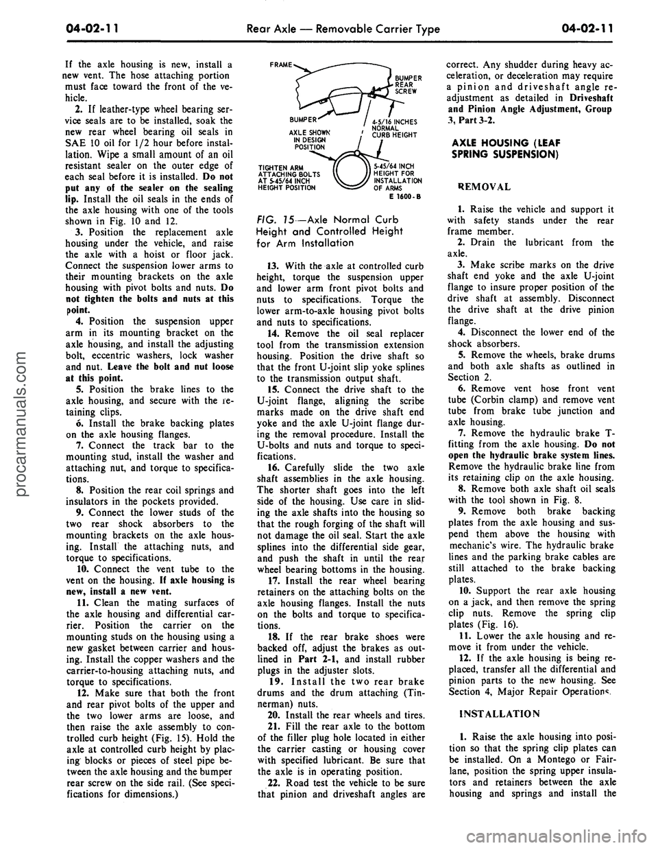
trolled curb height (Fig. 15). Hold the
axle at controlled curb height by plac-
ing blocks or pieces of steel pipe be-
tween the axle housing and the bumper
rear screw on the side rail. (See speci-
fications for dimensions.)
FRAME
TIGHTEN ARM
ATTACHING BOLTS
AT 5-45/64 INCH
HEIGHT POSITION
5-45/64 INCH
HEIGHT FOR
INSTALLATION
OF ARMS
E 1600-B
FIG. 75 -Axle Normal Curb
Height and Controlled Height
for Arm Installation
13.
With the axle at controlled curb
height, torque the suspension upper
and lower arm front pivot bolts and
nuts to specifications. Torque the
lower arm-to-axle housing pivot bolts
and nuts to specifications.
14.
Remove the oil seal replacer
tool from the transmission extension
housing. Position the drive shaft so
that the front U-joint slip yoke splines
to the transmission output shaft.
15.
Connect the drive shaft to the
U-joint flange, aligning the scribe
marks made on the drive shaft end
yoke and the axle U-joint flange dur-
ing the removal procedure. Install the
U-bolts and nuts and torque to speci-
fications.
16.
Carefully slide the two axle
shaft assemblies in the axle housing.
The shorter shaft goes into the left
side of the housing. Use care in slid-
ing the axle shafts into the housing so
that the rough forging of the shaft will
not damage the oil seal. Start the axle
splines into the differential side gear,
and push the shaft in until the rear
wheel bearing bottoms in the housing.
17.
Install the rear wheel bearing
retainers on the attaching bolts on the
axle housing flanges. Install the nuts
on the bolts and torque to specifica-
tions.
18.
If the rear brake shoes were
backed off, adjust the brakes as out-
lined in Part 2-1, and install rubber
plugs in the adjuster slots.
19.
Install the two rear brake
drums and the drum attaching (Tin-
nerman) nuts.
20.
Install the rear wheels and tires.
21.
Fill the rear axle to the bottom
of the filler plug hole located in either
the carrier casting or housing cover
with specified lubricant. Be sure that
the axle is in operating position.
22.
Road test the vehicle to be sure
that pinion and driveshaft angles are
correct. Any shudder during heavy ac-
celeration, or deceleration may require
a pinion and driveshaft angle re-
adjustment as detailed in Driveshaft
and Pinion Angle Adjustment, Group
3,
Part 3-2.
AXLE HOUSING (LEAF
SPRING SUSPENSION)
REMOVAL
1.
Raise the vehicle and support it
with safety stands under the rear
frame member.
2.
Drain the lubricant from the
axle.
3.
Make scribe marks on the drive
shaft end yoke and the axle U-joint
flange to insure proper position of the
drive shaft at assembly. Disconnect
the drive shaft at the drive pinion
flange.
4.
Disconnect the lower end of the
shock absorbers.
5.
Remove the wheels, brake drums
and both axle shafts as outlined in
Section 2.
6. Remove vent hose front vent
tube (Corbin clamp) and remove vent
tube from brake tube junction and
axle housing.
7.
Remove the hydraulic brake T-
fitting from the axle housing. Do not
open the hydraulic brake system lines.
Remove the hydraulic brake line from
its retaining clip on the axle housing.
8. Remove both axle shaft oil seals
with the tool shown in Fig. 8.
9. Remove both brake backing
plates from the axle housing and sus-
pend them above the housing with
mechanic's wire. The hydraulic brake
lines and the parking brake cables are
still attached to the brake backing
plates.
10.
Support the rear axle housing
on a jack, and then remove the spring
clip nuts. Remove the spring clip
plates (Fig. 16).
11.
Lower the axle housing and re-
move it from under the vehicle.
12.
If the axle housing is being re-
placed, transfer all the differential and
pinion parts to the new housing. See
Section 4, Major Repair Operation*.
INSTALLATION
1.
Raise the axle housing into posi-
tion so that the spring clip plates can
be installed. On a Montego or Fair-
lane,
position the spring upper insula-
tors and retainers between the axle
housing and springs and install theprocarmanuals.com
Page 400 of 413
07-04-31
C-6 Automatic Transmission
07-04-31
ing. Install six of the seven mounting
bolts and torque them to specifica-
tion.
24.
Adjust the intermediate band as
detailed in Section 2 and install the
input shaft with the long splined end
inserted into the forward clutch as-
sembly.
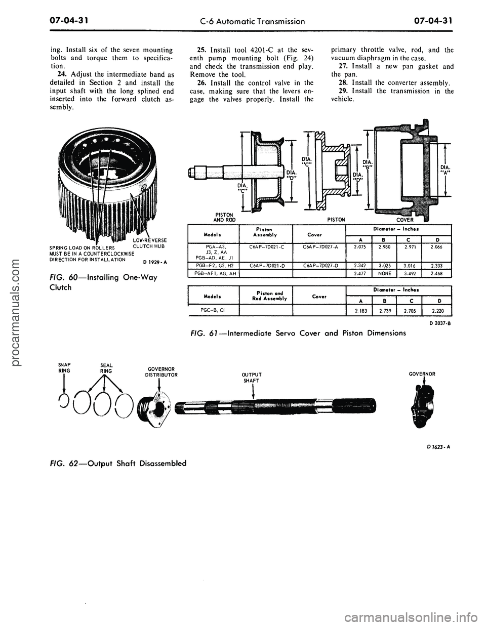
LOW-REVERSE
SPRING LOAD ON ROLLERS CLUTCH HUB
MUST BE IN A COUNTERCLOCKWISE
DIRECTION FOR INSTALLATION Q 192O A
FIG. 60—Installing One-Way
Clutch
25.
Install tool 4201-C at the sev-
enth pump mounting bolt (Fig. 24)
and check the transmission end play.
Remove the tool.
26.
Install the control valve in the
case,
making sure that the levers en-
gage the valves properly. Install the
primary throttle valve, rod, and the
vacuum diaphragm in the case.
27.
Install a new pan gasket and
the pan.
28.
Install the converter assembly.
29.
Install the transmission in the
vehicle.
PISTON
AND ROD
PISTON
COVER
Models
PGA-A3,
J3,
Z, AA
PGB-AD,
AE, Jl
PGB-F2/G2, H2
PGB-AF1,
AG, AH
Piston
Assembly
C6AP-7D021-C
C6AP-7D021-D
Cover
C6AP-7D027-A
C6AP-7D027-D
Diameter - Inches
A
2.075
2.342
2.477
' B
2.980
3.025
NONE
c
2.971
3.016
3.492
D
2.066
2.333
2.468
Models
PGC-B,
Cl
Piston and
Rod Assembly
Cover
Diameter
—
Inches
A
2.183
B
2.739
C
2.705
D
2.220
D 2037-B
FIG.
61
— Intermediate Servo Cover and Piston Dimensions
OUTPUT
SHAFT
GOVERNOR
D
1623
-A
FIG. 62—Output Shaft Disassembledprocarmanuals.com