driver seat adjustment FORD MUSTANG 1969 Volume One Chassis
[x] Cancel search | Manufacturer: FORD, Model Year: 1969, Model line: MUSTANG, Model: FORD MUSTANG 1969Pages: 413, PDF Size: 75.81 MB
Page 155 of 413

03-09-03
Saginaw Design Integral Power Steering Gear
03-09-03
shaft and install and tighten the attach-
ing bolts to specification.
6. Connect and tighten the fluid
pressure and the return line to the
steering gear.
7. Fill the power steering pump and
cycle the steering gear. Check for
leaks.
Check the reservoir fluid level
again and add as required.
MAJOR REPAIR OPERATIONS
Disassembly and reassembly of the
unit and the subassemblies must be
made on a clean workbench. As in re-
pairing any hyldraulically operated
unit, cleanliness is of tftfiiost impor-
tance. Therefore, the bench, tools, and
parts must be kept clean at all times.
Thoroughly clean the exterior of the
gear with a suitable solvent and, when
necessary, drain as much of the hy-
draulic fluid from the gear as possible.
DISASSEMBLY INTO
SUB-ASSEMBLIES
1,
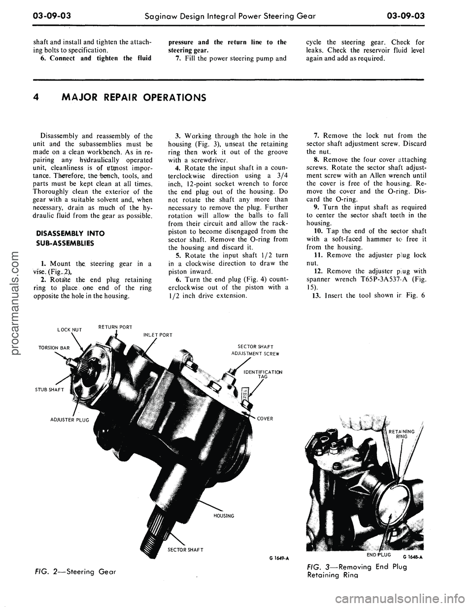
Mount the steering gear in a
vise.
(Fig..
2\
2.
Rotate the end plug retaining
ring to place one end of the ring
opposite the hole in the housing.
3.
Working through the hole in the
housing (Fig. 3), unseat the retaining
ring then work it out of the groove
with a screwdriver.
4.
Rotate the input shaft in a coun-
terclockwise direction using a 3/4
inch, 12-point socket wrench to force
the end plug out of the housing. Do
not rotate the shaft any more than
necessary to remove the plug. Further
rotation will allow the balls to fall
from their circuit and allow the rack-
piston to become disengaged from the
sector shaft. Remove the O-ring from
the housing and discard it.
5.
Rotate the input shaft 1/2 turn
in a clockwise direction to draw the
piston inward.
6. Turn the end plug (Fig. 4) count-
erclockwise out of the piston with a
1/2 inch drive extension.
7.
Remove the lock nut from the
sector shaft adjustment screw. Discard
the nut.
8. Remove the four cover attaching
screws. Rotate the sector shaft adjust-
ment screw with an Allen wrench until
the cover is free of the housing. Re-
move the cover and the O-ring. Dis-
card the O-ring.
9. Turn the input shaft as required
to center the sector shaft teeth in the
housing.
10.
Tap the end of the sector shaft
with a soft-faced hammer to free it
from the housing.
11.
Remove the adjuster plug lock
nut.
12.
Remove the adjuster p>ug with
spanner wrench T65P-3A537-A (Fig.
15).
13.
Insert the tool shown ir Fig. 6
LOCK NUT RETUF™ P0RT
INLET PORT
TORSION BAR
STUB SHAFT
SECTOR SHAFT
ADJUSTMENT SCREW
ADJUSTER PLUG
HOUSING
SECTOR SHAFT
G
1649-
A
FIG. 2—Steering Gear
END PLUG
G1648-A
FIG. 3—Removing End Plug
Retaining Rinaprocarmanuals.com