check engine light FORD MUSTANG 1969 Volume One Chassis
[x] Cancel search | Manufacturer: FORD, Model Year: 1969, Model line: MUSTANG, Model: FORD MUSTANG 1969Pages: 413, PDF Size: 75.81 MB
Page 29 of 413
02-02-10
Brake System
02-02-10
brake adjustment then connect the
parking brake cable to the parking
brake lever (Fig. 8).
4.
Install the shoe guide (anchor
pin) plate on the anchor pin when so
equipped.
5.
Place the cable eye over the an-
chor pin with the crimped side toward
the backing plate.
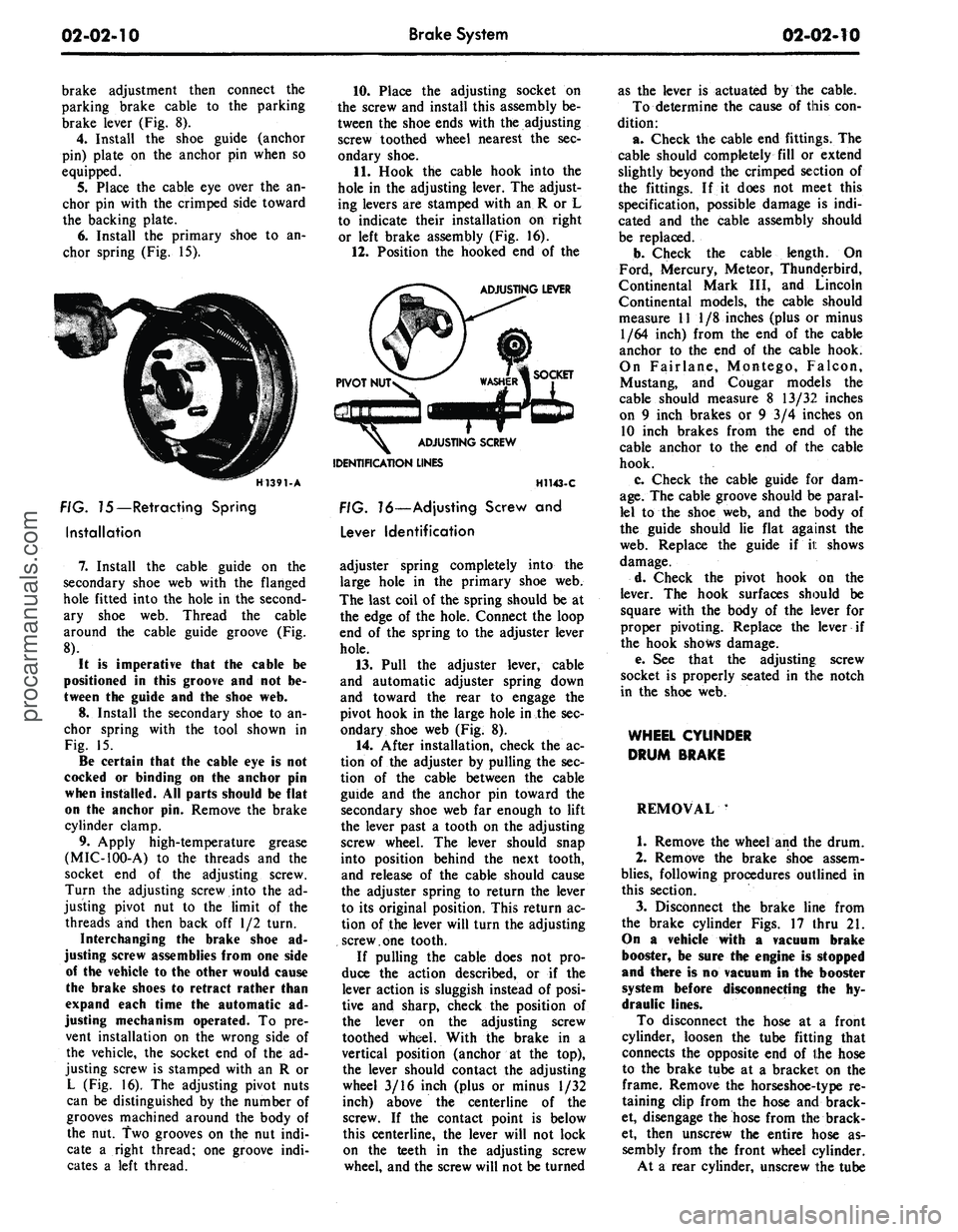
6. Install the primary shoe to an-
chor spring (Fig. 15).
H1391-A
FIG. 75—Retracting Spring
Installation
7.
Install the cable guide on the
secondary shoe web with the flanged
hole fitted into the hole in the second-
ary shoe web. Thread the cable
around the cable guide groove (Fig.
8).
It
is
imperative that
the
cable
be
positioned
in
this groove
and not be-
tween
the
guide
and the
shoe
web.
8.
Install the secondary shoe to an-
chor spring with the tool shown in
Fig. 15.
Be certain that
the
cable
eye is not
cocked
or
binding
on the
anchor
pin
when installed.
All
parts should
be
flat
on
the
anchor
pin.
Remove
the
brake
cylinder clamp.
9. Apply high-temperature grease
(MIC-100-A) to the threads and the
socket end of the adjusting screw.
Turn the adjusting screw into the ad-
justing pivot nut to the limit of the
threads and then back off 1/2 turn.
Interchanging
the
brake shoe
ad-
justing screw assemblies from
one
side
of
the
vehicle
to the
other would cause
the brake shoes
to
retract rather than
expand each time
the
automatic
ad-
justing mechanism operated.
To pre-
vent installation on the wrong side of
the vehicle, the socket end of the ad-
justing screw is stamped with an R or
L (Fig. 16). The adjusting pivot nuts
can be distinguished by the number of
grooves machined around the body of
the nut. Two grooves on the nut indi-
cate a right thread; one groove indi-
cates a left thread.
10.
Place the adjusting socket on
the screw and install this assembly be-
tween the shoe ends with the adjusting
screw toothed wheel nearest the sec-
ondary shoe.
11.
Hook the cable hook into the
hole in the adjusting lever. The adjust-
ing levers are stamped with an R or L
to indicate their installation on right
or left brake assembly (Fig. 16).
12.
Position the hooked end of the
ADJUSTING LEVER
IDENTIFICATION LINES
H1143-C
FIG. 16—Adjusting Screw
and
Lever Identification
adjuster spring completely into the
large hole in the primary shoe web.
The last coil of the spring should be at
the edge of the hole. Connect the loop
end of the spring to the adjuster lever
hole.
13.
Pull the adjuster lever, cable
and automatic adjuster spring down
and toward the rear to engage the
pivot hook in the large hole in the sec-
ondary shoe web (Fig. 8).
14.
After installation, check the ac-
tion of the adjuster by pulling the sec-
tion of the cable between the cable
guide and the anchor pin toward the
secondary shoe web far enough to lift
the lever past a tooth on the adjusting
screw wheel. The lever should snap
into position behind the next tooth,
and release of the cable should cause
the adjuster spring to return the lever
to its original position. This return ac-
tion of the lever will turn the adjusting
screw.one tooth.
If pulling the cable does not pro-
duce the action described, or if the
lever action is sluggish instead of posi-
tive and sharp, check the position of
the lever on the adjusting screw
toothed wheel. With the brake in a
vertical position (anchor at the top),
the lever should contact the adjusting
wheel 3/16 inch (plus or minus 1/32
inch) above the centerline of the
screw. If the contact point is below
this centerline, the lever will not lock
on the teeth in the adjusting screw
wheel, and the screw will not be turned
as the lever is actuated by the cable.
To determine the cause of this con-
dition:
a. Check the cable end fittings. The
cable should completely fill or extend
slightly beyond the crimped section of
the fittings. If it does not meet this
specification, possible damage is indi-
cated and the cable assembly should
be replaced.
b.
Check the cable length. On
Ford, Mercury, Meteor, Thunderbird,
Continental Mark III, and Lincoln
Continental models, the cable should
measure 11 1/8 inches (plus or minus
1/64 inch) from the end of the cable
anchor to the end of the cable hook.
On Fairlane, Montego, Falcon,
Mustang, and Cougar models the
cable should measure 8 13/32 inches
on 9 inch brakes or 9 3/4 inches on
10 inch brakes from the end of the
cable anchor to the end of the cable
hook.
c. Check the cable guide for dam-
age.
The cable groove should be paral-
lel to the shoe web, and the body of
the guide should lie flat against the
web.
Replace the guide if it shows
damage.
d. Check the pivot hook on the
lever. The hook surfaces should be
square with the body of the lever for
proper pivoting. Replace the lever if
the hook shows damage.
e. See that the adjusting; screw
socket is properly seated in the notch
in the shoe web.
WHEEL CYLINDER
DRUM BRAKE
REMOVAL '
1.
Remove the wheel and the drum.
2.
Remove the brake shoe assem-
blies,
following procedures outlined in
this section.
3.
Disconnect the brake line from
the brake cylinder Figs. 17 thru 21.
On
a
vehicle with
a
vacuum brake
booster,
be
sure
the
engine
is
stopped
and there
is no
vacuum
in the
booster
system before disconnecting
the hy-
draulic lines.
To disconnect the hose at a front
cylinder, loosen the tube fitting that
connects the opposite end of the hose
to the brake tube at a bracket on the
frame. Remove the horseshoe-type re-
taining clip from the hose and brack-
et, disengage the hose from the brack-
et, then unscrew the entire hose as-
sembly from the front wheel cylinder.
At a rear cylinder, unscrew the tubeprocarmanuals.com
Page 43 of 413
02-02-24
Brake
System
02-02-24
proportioning valve to the fender
apron and remove the proportioning
valve.
Installation
1.
Position the proportioning valve
to the fender apron.
2.
Connect the two brake lines at
the proportioning valve. Do not tight-
en.
3.
Install the bolt retaining the pro-
portioning valve to the fender apron.
4.
Tighten the brake line tube nuts
at the proportioning valve to specifica-
tions.
5.
Bleed the brakes and centralize
pressure differential valve.
THUNDERBIRD AND
CONTINENTAL MARK III
Removal
Refer to Fig. 20.
1.
Disconnect the two hydraulic
brake lines at the master cylinder.
2.
Remove the two nuts retaining
the master cylinder to the booster and
remove the master cylinder for clear-
ance.
3.
Disconnect the two brake lines at
the proportioning valve.
4.
Remove the bolt and nut retain-
ing the proportioning valve to the
pressure differential valve bracket and
remove the proportioning valve assem-
bly.
Installation
1.
Transfer the bracket to the new
proportioning valve.
2.
Position the proportioning valve
assembly to the pressure differential
valve bracket.
3.
Connect the two brake lines to
the proportioning valve. Do not tight-
en.
4.
Install the bolt and nut retaining
the proportioning valve to the pressure
differential valve bracket.
5.
Tighten the two brake line tube
nuts at the proportioning valve to
specifications.
6. Position the master cylinder to
the booster and install the nuts retain-
ing the master cylinder to the booster.
7.
Connect the two brake lines at
the master cylinder and tighten the
tube nuts to specifications.
8. Bleed the brakes and centralize
the pressure differential valve.
LINCOLN CONTINENTAL
Removal
Refer to Fig. 21.
1.
Disconnect the two brake lines at
the proportioning valve.
2.
Loosen the bolt and nut on the
bracket retaining the proportioning
valve to the chassis.
3.
Remove the proportioning valve
from the bracket.
Installation
- 1. Position the proportioning valve
in the bracket and connect the two
brake lines. Do not tighten.
2.
Tighten the bolt and nut on the
bracket.
3.
Tighten the tube nuts on the
brake lines at the proportioning valve
to specifications.
4.
Bleed the brakes and centralize
the pressure differential valve.
PRESSURE METERING VALVE—
LINCOLN CONTINENTAL
REMOVAL
Refer to Fig. 21.
1.
Loosen the tube nuts connecting
the inlet and outlet tubes at the me-
tering valve, and remove the tubes.
2.
Remove the two screws retaining
the metering valve to the frame
crossmember, and remove the me-
tering valve. The metering valve is ser-
viced as an assembly only.
INSTALLATION
1.
Position the metering valve to
the frame crossmember, and install
the retaining screws.
2.
Connect the inlet and outlet
tubes to the metering valve, and tight-
en the tube nuts to specification.
BRAKE BOOSTER
REMOVAL
1.
Working from inside the\ vehicle
below the instrument panel, disconnect
the booster push rod from the brake
pedal assembly. To do this, proceed as
follows:
Disconnect the stop light switch
wires at the connector. Remove the
hairpin retainer. Slide the stop light
switch off from the brake pedal pin
just far enough for the switch outer
hole to clear the pin, and then remove
the switch from the pin and booster
push rod. Be careful not to damage
the switch during removal. Slide the
booster push rod and the nylon wash-
ers and bushing off the brake pedal
pin (Figs. 29 thru 33).
2.
Open the hood and remove the
master cylinder from the booster. Se-
cure it to one side without disturbing
the hydraulic lines. It is not necessary
to disconnect the brake lines, but care
should be taken that the brake lines
are not deformed. Permanent defor-
mation of brake lines can lead to tube
failure.
3.
Disconnect the manifold vacuum
hose or hoses from the booster unit.
4.
Remove the booster-to-dash
panel attaching nuts or bolts (Figs. 29
thru 33). Remove the booster and
bracket assembly from the dash panel,
sliding the push rod link out from the
engine side of the dash panel.
5.
On Fairlane, Montego, and Fal-
con models, remove the push rod link
boot from the dash panel.
INSTALLATION
1.
On Fairlane, Montego and Fal-
con models, install the push rod link
boot in the hole in the dash panel as
shown in Fig. 23. Install the four
spacers on the mounting studs.
2.
Mount the booster and bracket
assembly to the dash panel by insert-
ing the push rod or push rod link in
through the hole and boot in the dash
panel. Install the bracket-to-dash
panel attaching lock nuts or bolts
(Figs.
29 thru 33).
3.
Connect the manifold vacuum
hose or hoses to the booster.
4.
Before installing the master cyl-
inder, check the distance from the
outer end of the booster assembly
push rod to master cylinder surface.
Turn the screw in or out to obtain the
specified length. Refer to Part 2-1,
Section 2, Power Brake Master Cylin-
der Push Rod Adjustment. Install the
master cylinder and torque the attach-
ing nuts to specifications.
5.
Working from inside the vehicle
below the instrument panel, connect
the booster push rod link to the brake
pedal assembly. To do this, proceed as
follows:
Install the inner nylon washer, the
booster push rod, and the bushing on
the brake pedal pin. Position the
switch so that it straddles the push
rod with the switch slot on the pedal
pin and the switch outer hole justprocarmanuals.com
Page 44 of 413
02-02-25
Brake System
02-02-25
clearing the pin. Slide the switch com-
pletely onto the pin, and install the
nylon washer as shown in Figs. 29
thru 33. Be careful not to bend or de-
form the switch. Secure these parts to
the pin with the hairpin retainer. Con-
nect the stop light switch wires to the
connector, and install the wires in the
retaining clip.
BRAKE PEDAL
FORD, MERCURY
AND METEOR
Removal
1.
Disconnect the stop light switch
wires at the connector.
2.
Remove the hairpin retainer.
Slide the stop light switch off the
brake pedal pin just far enough for
the switch outer hole to clear the pin,
and then lift the switch straight up-
ward from the pin. Be careful not to
damage the switch during removal.
Slide the master cylinder or booster
push rod and the nylon washers and
bushing off the brake pedal pin (Figs.
26 and 29).
3.
Remove the hairpin type retainer
and washer from the brake pedal
shaft, then remove the shaft, the brake
pedal and the bushings from the pedal
support bracket.
Installation
1.
Apply a coating of SAE 10 En-
gine oil to the bushings and locate
bushings in their proper places on the
pedal assembly and pedal support
bracket (Figs. 26 and 29).
2.
Position the brake pedal assem-
bly to the support bracket, then install
the pedal shaft through the support
bracket and brake pedal assembly. In-
stall the retainer.
3.
Install the inner nylon washer,
the master cylinder or booster push
rod, and the bushing on the brake
pedal pin. Position the switch so that
it straddles the push rod with the
switch slot on the pedal pin and the
switch outer hole just clearing the pin.
Slide the switch completely onto the
pin, and install the nylon washer as
shown in Figs. 26 and 29. Be careful
not to bend or deform the switch. Se-
cure these parts to the pin with the
hairpin retainer.
4.
Connect the stop light switch
wires to the connector, and install the
wires in the retaining clip.
5.
Check the Brake Pedal Free
Height and Travel Measurements,
Part 2-1, Section 1.
FAIRLANE, MONTEGO AND
FALCON—MANUAL-SHIFT
TRANSMISSION
Removal
1.
Remove the clutch pedal assist
spring.
2.
Disconnect the clutch pedal-
to-equalizer rod at the clutch pedal by
removing the retainer and bushing.
3.
Disconnect the stop light switch
wires at the connector.
4.
Remove the switch retainer, and
slide the stop light switch off the
brake pedal pin just far enough for
the switch outer hole to clear the pin.
Then lower the switch away from the
pin.
5. Slide the master cylinder or
booster push rod and the nylon wash-
ers and bushing off from the brake
pedal pin (Figs. 27 and 30).
6. Remove the self-locking pin and
washer from the clutch and brake
pedal shaft, then remove the clutch
pedal and shaft assembly, the brake
pedal assembly, and the bushings from
the pedal support bracket (Figs. 27
and 30).
Installation
1.
Apply a coating of SAE 10 en-
gine oil to the bushings and locate all
bushings in their proper places on the
clutch and brake pedal assemblies.
2.
Position the brake pedal to the
support bracket, then install the clutch
pedal and shaft assembly through the
support bracket and brake pedal as-
sembly. Install the spring clip (Figs.
27 and 30).
3.
Install the clutch pedal assist
spring.
4.
Connect the clutch pedal-
to-equalizer rod to the clutch pedal
assembly with the bushing and the
spring clip retainer. Apply SAE 10
engine oil to the bushing.
5.
Install the inner nylon washer,
the master cylinder or booster push
rod, and the bushing on the brake
pedal pin. Position the switch so that
it straddles the push rod with the
switch slot on the pedal pin and the
switch outer hole just clearing the pin.
Slide the switch completely onto the
pin, and install the outer nylon washer
as shown in Figs. 27 and 30. Secure
these parts to the pin with the
self-
locking pin.
6. Connect the stop light switch
wires to the connector, and install the
wires to the retaining clip.
7.
Adjust the clutch pedal free play
(Group 5) to specification, if required.
8. Check the Brake Pedal Free
Height and Travel Measurements
(Part 2-1, Section 1).
MUSTANG AND COUGAR—
MANUAL-SHIFT
TRANSMISSION
Removal
1.
Disconnect the battery ground
cable from the battery.
2.
Remove the steering column.
Refer to Part 3-4, Section 2 for pro-
cedure.
3.
On non-power brakes, remove
the two cap screws retaining the mas-
ter cylinder to the dash panel and re-
move the two cap screws retaining the
brake pedal support bracket to the
dash panel. On power brakes remove
the two cap screws retaining the
booster to the dash panel.
4.
Working inside the vehicle, se-
cure the clutch pedal against the
bumper stop with a small C-clamp as
shown in Figs. 28 and 31.
5.
Disconnect the clutch pedal-
to-equalizer rod at the clutch pedal by
removing the retainer and bushing.
6. Disconnect the stop light switch
wires at the connector.
7.
Remove the switch retainer and
slide the stop light switch off the
brake pedal pin just far enough for
the switch outer hole to clear the pin.
Then lower the switch away from the
pin.
Remove the master cylinder or
booster push rod, bushing and nylon
washer from the brake pedal pin.
8. Remove the screw retaining the
pedal support bracket to the top inner
cowl bracket (Figs. 28 and 31).
9. Remove the two sheet metal
screws retaining the pedal support
bracket to the dash panel. On power
brakes remove the nuts from the
brake booster studs.
10.
Remove the two screws retain-
ing the pedal support bracket to the
upper cowl brace and lower the pedal
support bracket away from the steer-
ing column studs.
11.
Remove the pedal support
bracket assembly from the vehicle.
12.
Position the pedal and support
bracket assembly in a vise.
13.
Remove the C-clamp to release
the clutch pedal from its bumper stop
and pivot the pedal away from the
bumper.procarmanuals.com
Page 45 of 413
02-02-26
Brake System
02-02-26
14.
Remove the clutch pedal assist
spring.
15.
On non-power brakes, remove
the retainer clip from the clutch and
brake pedal shaft, then remove the
clutch pedal and shaft assembly, the
brake pedal assembly, and the bush-
ings from the pedal support bracket.
On power brakes, remove the retainer
nut from the brake pedal shaft then
remove the pedal shaft, the brake
pedal assembly and the bushings from
the pedal support bracket.
Installation
1. Apply a coating of SAE 10 en-
gine oil to the bushings and locate all
bushings in their proper places on the
clutch and brake pedal assemblies.
2.
On non-power brakes, position
the brake pedal to the pedal support
bracket, then install the clutch pedal
and shaft assembly through the sup-
port bracket and brake pedal assem-
bly. On power brakes position the
brake pedal to the pedal support
bracket, then install the pedal shaft
and nut.
3.
Install the clutch pedal assist
spring and pivot the clutch pedal
against its bumper stop. Secure the
pedal to the stop with a small C-
clamp as shown in Figs. 28 and 31.
4.
Position the pedal support
bracket assembly to the dash panel,
and to the steering column retainer
studs.
5.
Align the pedal support bracket
holes with the holes in the dash panel
and install the two attaching sheet
metal screws. On power brakes install
the nuts on the brake booster studs.
6. Install the two cap screws at-
taching the pedal support bracket to
the upper cowl bracket.
7. Install the cap screw attaching
the pedal support bracket to the top
inner cowl bracket (Figs. 28 and 31).
8. Install the inner nylon washer,
the master cylinder push rod, and the
bushing on the brake pedal pin. Posi-
tion the stop light switch so that it
straddles the push rod with the switch
slot on the pedal pin and the switch
outer hole just clearing the pin. Slide
the switch completely onto the pin,
and install the outer nylon washer as
shown in Figs. 28 and 31. Secure
these parts to the pin with the
self-
locking retainer.
9. Connect the stop light switch
wires to the connector.
10.
Connect the clutch pedal-
to-equalizer rod to the clutch pedal
assembly with the bushing and the
spring clip retainer. Apply SAE 10
engine oil to the bushing. Remove the
C-clamp from the clutch pedal.
11.
Working from the engine side
of the dash panel, on non-power
brakes, install the two cap screws at-
taching the pedal support bracket to
the dash panel. Then install the two
screws attaching the master cylinder
to the dash panel. On power brakes
install the cap screws retaining the
brake booster to the dash panel.
12.
Install the steering column.
Refer to Part 3-4, Section 2 for pro-
cedure.
13.
Adjust the clutch pedal free
play (Group 5) to specification, if re-
quired.
14.
Check the Brake Pedal Free
Height and Travel Measurements
(Part 2-1, Section 1).
15.
Connect the ground cable to the
battery.
FAIRLANE, MONTEGO,
FALCON, MUSTANG
AND COUGAR-
AUTOMATIC TRANSMISSION
Removal
1. Disconnect the stop light switch
wires at the connector.
2.
Remove the self-locking pin and
slide the stop light switch off the
brake pedal pin just far enough for
the switch outer hole to clear the pin.
Then lower the switch away from the
pin. Slide the master cylinder or
booster push rod and the nylon wash-
ers and bushing off from the brake
pedal pin (Figs. 27, 28, 30 and 31).
3.
On all vehicles except Mustang
and Cougar with power brakes, re-
move the self-locking pin and washer
from the brake pedal shaft, then re-
move the shaft, the brake pedal as-
sembly and the bushings from the
pedal support bracket. On Mustang
and Cougar vehicles with power
brakes, remove the locknut and bolt
from the pedal. Remove the pedal as-
sembly from the support bracket (Fig.
3).
Installation
1. Apply a coating of SAE 10 en-
gine oil to the bushings and locate all
the bushings in their proper places on
the pedal assembly and pedal support
bracket (Figs. 27, 28, 30 and 31).
2.
Position the brake pedal assem-
bly to the support bracket, then install
the pedal shaft or bolt through the
support bracket and brake pedal as-
sembly. Install the retainer or locknut.
3.
Install the inner nylon washer,
the master cylinder or booster push
rod, and the bushing on the brake
pedal pin. Position the switch so that
it straddles the push rod with the
switch slot on the pedal pin, and the
switch outer hole just clearing the pin.
Slide the switch completely onto the
pin, and install the outer nylon washer
as shown in Figs. 27, 28, 30 and 31.
Secure these parts to the pin with the
self-locking pin.
4.
Connect the stop light switch
wires to the connector, and install the
wires in the retaining clip.
Check the Brake Pedal Free Height
and Travel Measurements, Part 2,
Section 1.
THUNDERBIRD
AND
CONTINENTAL MARK
III
Removal
1.
Loosen the booster mounting
nuts.
2.
Disconnect the stop light switch
wires at the connector.
3.
Remove the hairpin retainer.
Slide the stop light switch off from
the brake pedal pin just far enough
for
the
switch outer hole
to
clear
the
pin,
and then lift the switch straight
upward from the pin. Slide the master
cylinder push rod and the nylon wash-
ers and bushing off from the brake
pedal pin (Fig. 32).
4.
Remove the pivot bolt and nut
that holds the pedal to the pedal sup-
port bracket. Remove the brake pedal
assembly from the pedal support
bracket, and remove the bushings.
Installation
1. Apply a coating of SAE 10 en-
gine oil to the bushings and locate all
the bushings in their proper places on
the pedal assembly (Fig. 32).
2.
Install the brake pedal assembly
and bushings to the support bracket,
and then install the pivot bolt through
the support bracket and brake pedal
assembly. Install the pivot bolt nut
and torque to specifications.
3.
Install the inner nylon washer,
the master cylinder push rod, and the
bushing on the brake pedal pin. Posi-
tion the switch so that it straddles the
push rod with the switch slot on the
pedal pin and the switch outer hole
just clearing the pin. Slide the switch
completely onto the pin, install the
outer nylon washer as shown in Fig.
32.
Secure these parts to the pin with
the hairpin retainer.procarmanuals.com
Page 46 of 413
02-02-27
Brake System
02-02-27
4.
Connect the stop light switch
wires to the connector, and install the
wires in the retaining clip.
5.
Torque the booster mounting
nuts to specifications.
LINCOLN CONTINENTAL
Removal
1.
Disconnect the battery ground
cable from the battery.
2.
It is necessary to obtain clear-
ance to remove vacuum hoses and the
electrical connector to the temperature
heat control box. Remove the two
screws retaining the relay to the fend-
er and push the relay aside. Discon-
nect the vacuum hoses and connector
at the heat control box.
3.
Working under the instrument
panel, disconnect the vacuum hoses,
wires and retaining clip from the tem-
perature heat control box. Remove the
two screws securing the temperature
control box to the dash panel.
4.
Remove the lower control hous-
ing retaining screws (6). Disconnect
the wire harnesses at the lower control
panel and place the panel aside. Re-
move the wire harness shield. Remove
the wire harness clip. Position the
wire harness aside. Remove the tem-
perature control box and position it
aside.
5.
Remove the hair-pin type retain-
er. Slide the stop light switch off the
brake pedal pin just far enough for
the switch outer hole to clear the pin.
Lift the switch upward from the pin.
Slide the master cylinder push rod,
nylon washers and bushing off the
brake pedal pin.
6. Remove the pivot bolt and nut
that holds the pedal to the pedal sup-
port bracket. Remove the brake pedal
assembly from the support bracket
and remove the bushings.
7.
If required, remove the brake
pedal pad retaining nuts and remove
the brake pedal pad.
Installation
1.
If the brake pedal pad was re-
moved, position the pad on the pedal.
Install the pad retaining nuts and tor-
que them to specification.
2.
Apply SAE 10 engine oil to the
bushings and locate all the bushings in
their proper places on the pedal as-
sembly.
3.
Install the brake pedal assembly
and bushings to the support bracket,
and then install the pivot bolt through
the support bracket and pedal assem-
bly. Install the pivot bolt nut and tor-
que it to specification.
4.
Install the inner nylon washer,the
master cylinder push rod link, and the
bushing on the brake pedal pin. Posi-
tion the switch so that it straddles the
push rod link with the switch slot on
the pedal and the switch outer hole
just clearing the pin. Install the outer
nylon washer as shown in Fig. 33. In-
stall the hair-pin type retainer on the
brake pedal pin.
5.
Connect the stop light switch
wires to the connector, and install the
wires in the retaining clip.
6. Position the wire harness and
clip on the temperature control box
and install the retaining screw. Posi-
tion the temperature control box to
the dash panel and install the two re-
taining bolts.
7.
Connect the vacuum lines and
the electrical connector to the control
box. Position the wire harness to the
control box and install the retaining
clip.
8. Position the wire harness shield
and install two retaining bolts.
9. Connect the wire harnesses to
the lower control panel and install the
retaining screws.
10.
Working within the engine
compartment, connect the wire con-
nector to the temperature heat control
box.
11.
Position the relay to the fender
apron and install the retaining bolts.
12.
Connect the ground cable to the
battery.
13.
Check the brakes and light
switch for proper operation. Close the
hood.
PARKING BRAKE CONTROL
ASSEMBLY
FORD, MERCURY
AND METEOR
Removal
Refer to Fig. 34.
1.
Make sure the parking brake is
fully released.
2.
Remove all tension from the rear
cables by backing off the adjusting nut
from the equalizer.
3.
Remove the roll pin that secures
the release knob to the cable and re-
move the knob.
4.
Remove the nut that secures the
release cable to the instrument panel
and remove the cable from the rear of
the instrument panel.
5.
Remove the two nuts attaching
the control assembly to the dash
panel.
6. Remove the cap screw attaching
the control assembly to the cowl side
bracket.
7.
Disconnect the hose to the park-
ing brake vacuum unit, if so equipped.
8. Remove the front cable assembly
retainer clip from the cable assembly
and disconnect the cable ball from the
control clevis.
9. Remove the control assembly
from the vehicle.
Installation
1.
Position the control assembly in
the vehicle.
2.
Fit the cable assembly through
its mounting hole and install the re-
taining clip. Connect the cable ball to
the control clevis.
3.
Connect the vacuum hose to the
parking brake unit, if so equipped.
4.
Install the attaching cap screw to
the cowl side bracket. Do not tighten.
5.
Install the two control assemb-
ly-to-dash panel nuts. Tighten the nuts
and the cap screw to specifications.
6. Insert the release cable into the
instrument panel and install the re-
taining nut.
7.
Install the release knob on the
cable with the roll pin.
8. Check the operation of the park-
ing brake. Adjust the parking brake
as required.
FAIRLANE, MONTEGO
AND FALCON
Removal
Refer to Fig. 35.
1.
Make sure the parking brake is
completely released.
2.
Remove all tension from the rear
cables by backing off the jam nut and
adjusting nut from the equalizer.
3.
Working inside the vehicle, re-
move the four bolts and one nut re-
taining the left air vent and cable as-
sembly to the dash and instrument
panels. Remove the vent assembly.
4.
Remove the parking brake front
cable ball retaining clip from the clev-
is.
5.
Disconnect the cable ball from
the notch in the brake clevis.
6. Remove the three screws that at-
tach the control assembly to the left
cowl inner side panel.procarmanuals.com
Page 94 of 413
03-02-18
Suspension
03-02-18
5.
Remove the cotter pin from the
upper ball joint stud nut.
6. Loosen the upper ball joint stud
nut one or two turns. Do not remove
the nut from the stud at this time.
7.
Install tool T57P-3006-A be-
tween the upper and lower ball joint
studs with the adapter screw on top
(Fig. 13). The tool should be seated
firmly against the ends of both studs
and not against the nuts or lower stud
cotter pin.
8. With a wrench, turn the adapter
screw until the tool places the stua
under tension. Tap the spindle near
the upper stud with a hammer to loos-
en the stud in the spindle. Do not
loosen the stud from the spindle with
tool pressure only.
9. Remove the tool from between
the ball joint studs and place a floor
jack under the lower arm.
10.
Raise the floor jack to relieve
the pressure from the upper ball joint
stud nut and remove the nut.
11.
Remove the upper arm inner
shaft attaching bolts. Remove the
upper arm and inner shaft as an as-
sembly (Fig. 1).
12.
Remove the bumpei from the
upper arm.
Installation
1.
Position the bumper to the upper
arm and install the nut and washer.
Torque the nut to specifications.
2.
Position the upper arm inner
shaft to the frame side rail and install
the 2 attaching bolts and washers
snug.
3.
Connect the upper ball joint stud
to the spindle and install the attaching
nut. Torque the nut to specification
and continue to tighten the nut until
the cotter pin hole in the stud is in
line with the nut slots. Then, install
the cotter pin.
4.
If equipped with drum type bra-
kes—Adjust the brakes as outlined in
Part 2-2. Install the wheel, tire, and
drum to the spindle and adjust the
wheel bearings as outlined in Part
3-12.
5.
If equipped with disc brak-
es—Install the wheel and tire on the
hub and adjust the wheel bearings as
outlined in Part 3-12.
6. Install the hub cap or wheel
cover.
7.
Remove the safety stands and
lower the front of the vehicle.
8. Check caster, camber, and toe-in
and adjust as required (Section 2, Part
3-D.
COUGAR, FAIRLANE,
FALCON, MONTEGO,
MUSTANG
Removal
1.
Raise the front of the vehicle,
position safety stands under the
frame, and lower the vehicle slightly.
2.
Remove the wheel and tire.
3.
Remove the shock absorber
lower attaching nuts and washers.
4.
Remove the shock absorber
upper mounting bracket attaching
nuts,
and remove the shock absorber
and bracket as an assembly (Fig. 26).
On all 8-cylinder vehicles, remove
the air cleaner to obtain access for
tool installation.
5.
Install the spring compressor
tool and compress the spring (Figs.
19,
20 and 21).
6. Position a safety stand under the
lower arm.
7.
Remove the cotter pin from the
nut on the upper ball joint stud, and
loosen the nut one or two turns. Do
not remove the nut from the stud at
this time.
8. Position the ball joint remover
tool between the upper and lower ball
joint studs as shown in Fig. 10. The
tool should seat firmly against the
ends of both studs and not against the
stud nuts.
9. Turn the tool with a wrench until
the tool places the studs under consid-
erable tension; then, hit the spindle
smartly near the upper stud with a
hammer to break the stud loose in the
spindle. Do not loosen the stud in the
spindle with tool pressure only. If
both arms are being removed, loosen
the lower stud in the same manner as
the upper stud.
10.
Remove the nut from the upper
stud and lift the stud out of the
spindle.
11.
Remove the upper arm inner
shaft attaching nuts from the engine
compartment, and remove the upper
arm.
12.
Wipe off all loose dirt from the
upper arm parts. Do not wash the ball
joint with a solvent.
Installation
1.
Position the upper arm on the
underbody mounting bracket, and in-
stall the nuts and lock washers on the
two inner shaft attaching bolts. The
specified keystone-type lock washers
must be used. Torque the nuts to
soecification.
2.
Position the upper ball joint stud
in the top of the wheel spindle, and in-
stall the stud nut. Torque the nut to
specification, and continue to tighten
it until the cotter pin hole and slots
line up. Install a new cotter pin.
3.
Release the coil spring, remove
the tool, and install the front shock
absorber and the wheel and tire.
LINCOLN CONTINENTAL
Removal
1.
Place a jack under the outer end
of the suspension lower arm and raise
the arm. Refer to Fig. 22.
2.
Remove the wheel and tire.
3.
Remove the cotter pin from the
upper ball joint stud. Loosen the nut
one or two turns.
4.
Place a box wrench over the
lower end of the ball joint remover
tool, and position the tool as in Fig.
13.
The tool should seat firmly against
the ends of both studs, and not
against the upper stud nut.
5.
Turn the wrench until both studs
are under tension, and then, tap the
spindle with a hammer near the upper
stud to loosen it from the spindle. Do
not loosen the stud with tool pressure
alone. Remove the nut.
UPPER MOUNTING BRACKET
LOWER RETAINING BOLTS F 1490-A
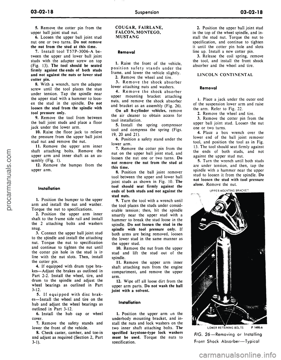
FIG. 26—Removing or Installing
Front Shock Absorber—Typicalprocarmanuals.com
Page 112 of 413
03-04-03
Automatic Air Leveling System — Lincoln Continental
03-04-03
outlet lines to their respective parts.
3.
Adjust the trim height as de-
tailed in Section 4.
4.
Connect the link to the arm.
5.
Remove the jack stands and
lower the vehicle.
SUPER LIFT SHOCK ABSORBER
REMOVAL
1.
Raise the vehicle and place jack
stands under the axle to compress the
super lift.
2.
Loosen the air line or lines (right
super lift) slowly to release the air
from the system. Then, disconnect the
line or lines.
3.
Remove the three mounting plate
attaching screws from the upper end
of the super lift.
4.
Remove the attaching nut and
washer from the lower end of the
super lift and remove it from the vehi-
cle.
5.
Remove the nut, outer washer
and the insulator that attach the super
lift to the mounting plate. Remove the
plate, remaining insulator and washer.
INSTALLATION
1.
Position a washer, insulator,
mounting plate, insulator, washer and
nut on the stud at the upper end of
the super lift. Torque the nut to speci-
fication.
2.
Install the mounting plate, outer
insulator, washer and nut on the stud.
Torque the nut to specification.
3.
Attach the mounting plate and
shock absorber to the crossmember
with the attaching screws to specifica-
tions.
4.
Connect the lower end of the
super lift to the mounting stud with
the washers and attaching nut. Torque
the nut to specification.
5.
Connect the air line or lines
(right super lift) to the super lift.
6. Start the engine and check for
leaks.
3 IN-VEHICLE ADJUSTMENTS AND REPAIRS
REGULATOR ADJUSTMENT HEIGHT CONTROL VALVE
The regulator may be adjusted if
the regulator pressure is under 100 psi
with the reservoir pressure at a mini-
mum of 140 psi. If the regulated pres-
sure exceeds 130 psi, the regulator
must be replaced.
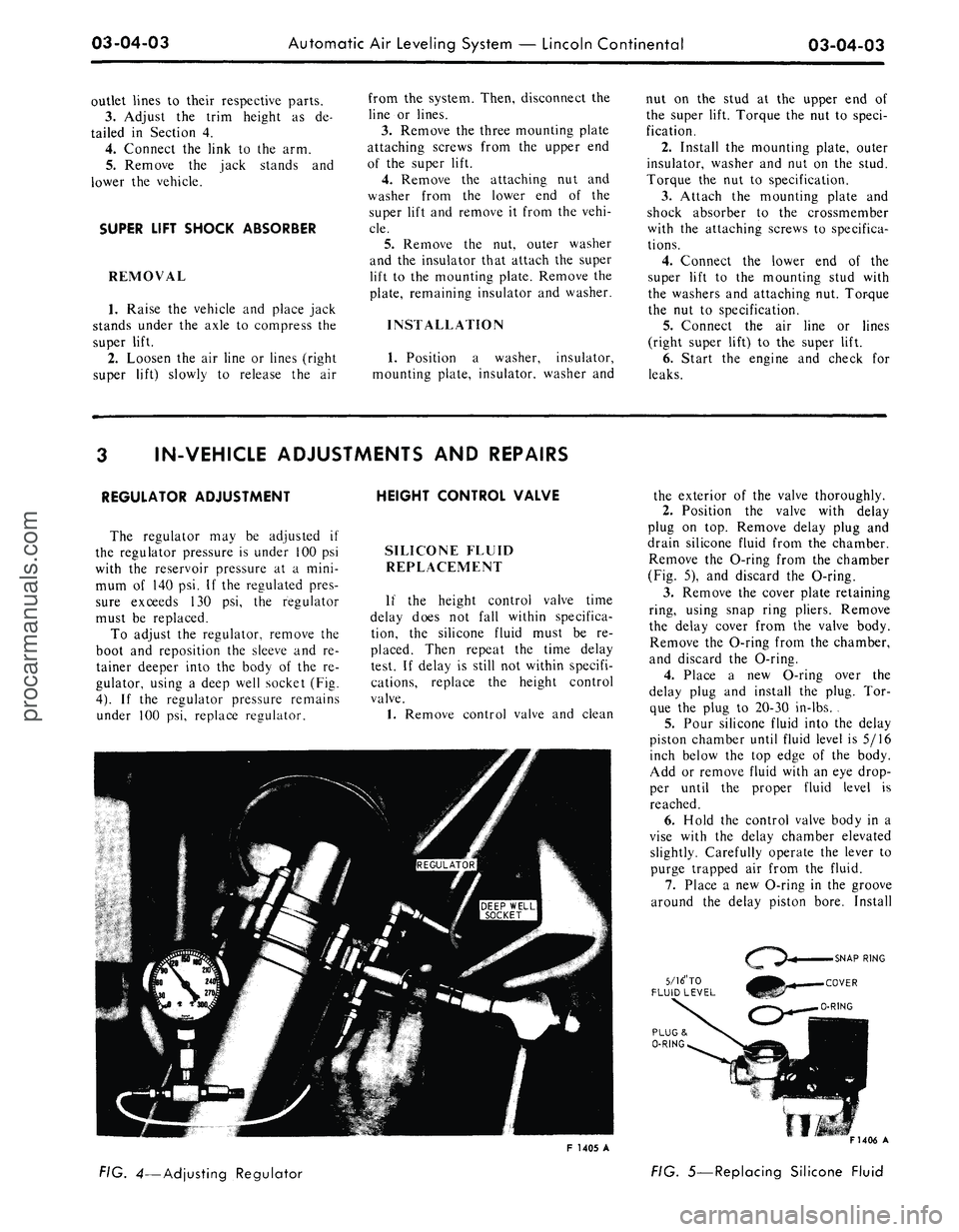
To adjust the regulator, remove the
boot and reposition the sleeve and re-
tainer deeper into the body of the re-
gulator, using a deep well socket (Fig.
4).
If the regulator pressure remains
under 100 psi, replace regulator.
SILICONE FLUID
REPLACEMENT
If the height control valve time
delay does not fall within specifica-
tion, the silicone fluid must be re-
placed. Then repeat the time delay
test. If delay is still not within specifi-
cations, replace the height control
valve.
1.
Remove control valve and clean
the exterior of the valve thoroughly.
2.
Position the valve with delay
plug on top. Remove delay plug and
drain silicone fluid from the chamber.
Remove the O-ring from the chamber
(Fig. 5), and discard the O-ring.
3.
Remove the cover plate retaining
ring, using snap ring pliers. Remove
the delay cover from the valve body.
Remove the O-ring from the chamber,
and discard the O-ring.
4.
Place a new O-ring over the
delay plug and install the plug. Tor-
que the plug to 20-30 in-lbs. .
5.
Pour silicone fluid into the delay
piston chamber until fluid level is 5/16
inch below the top edge of the body.
Add or remove fluid with an eye drop-
per until the proper fluid level is
reached.
6. Hold the control valve body in a
vise with the delay chamber elevated
slightly. Carefully operate the lever to
purge trapped air from the fluid.
7.
Place a new O-ring in the groove
around the delay piston bore. Install
5/16" TO
FLUID LEVEL
F 1405 A
FIG. 4—Adjusting Regulator
F1406 A
FIG. 5—Replacing Silicone Fluidprocarmanuals.com
Page 127 of 413
03-05-14
Steering Columns And Linkage
03-05-14
8. Connect the turn signal and
emergency flasher switch wires at the
multiple connectors. Connect the wires
to the neutral start switch. Adjust-
ments for the neutral start switch are
detailed in Group 7 of this manual.
9. Connect the tilt-column control
cable to the release cable retainer and
vacuum motor (if so equipped). To re-
move cable slack, loosen the bracket
attaching screw and pull it slightly
toward the column, then tighten the
screw. If difficulty in adjusting this
control is experienced, the retainer
slot may be filed to gain additional
travel.
10.
Install the instrument panel
steering column plate and cover and
the instrument panel lower outer fin-
ish panel.
11.
Connect the negative cable to
the battery.
12.
Start the engine and check the
operation of the steering column and
switches.
LINCOLN CONTINENTAL
Removal
1.
Disconnect the battery.
2.
Disconnect the rod from the
lever at the lower end of the selector
tube.
Loosen the clamp bolt that locks
the flexible coupling to the steering
shaft.
3.
Working from the underside of
the steering wheel spoke, remove the
two screws that secure the crash pad.
Remove the pad. Do not use a ham-
mer or knock-off type wheel puller.
Striking the puller or shaft may cause
damage to the bearings and/or col-
lapsible column. Remove the steering
wheel as shown in Fig. 15.
4.
Remove the instrument panel
steering column finish plate.
5.
Remove the four screws that at-
tach the lower retainer to the dash
panel.
6. Disconnect the turn signal switch
and emergency flasher wires at the
connectors. Disconnect the wires from
the neutral start switch.
7.
While supporting the steering
column, remove the bolts that attach
the lower clamp to the upper bracket
(Fig. 15). Lift the column from the ve-
hicle.
Installation
1.
Position the column in the vehi-
cle,
making sure that the steering
shaft engages the flex coupling.
2.
Install the column retainer-
to-dash panel attaching screws, but do
not tighten them.
3.
Install the lower clamp and the
attaching nuts. Tighten the nuts fing-
ertight.
4.
Move the lower flange as re-
quired to center the steering shaft in
the tube. Aligning procedures are de-
tailed in Part 3-1. Tighten the lower
flange attaching nuts when the shaft is
centered.
5.
Connect the shift rod to the shift
lever at the lower end of the column.
6. Install and tighten the flex cou-
pling attaching bolt.
7.
Tighten the instrument panel-
to-clamp attaching nuts.
8. Connect the turn signal and
emergency flasher switch wirss at the
multiple connectors. Connect the wires
to the neutral start switch. Adjust-
ments for the neutral start switch are
detailed in Group 7 of this manual.
9. Install the instrument panel
steering column finish plate.
10.
Install the steering wheel and
crash pad.
MAJOR REPAIR OPERATIONS
STEERING COLUMN
SHIFT TUBE REPLACEMENT
STATIONARY COLUMN
WITH STANDARD
TRANSMISSION
Removal
1.
Working from the underside of
the steering wheel spoke, remove the
two screws that secure the crash pad.
Remove the pad. (On Continental
Mark III models, pry out the crash
pad insert and remove the two screws
that secure the crash pad. Remove the
crash pad. On models equipped with
steering wheel mounted speed con-
trols,
refer to Group 16 for removal
instructions).
2.
Remove the steering wheel from
the steering shaft with tool T67L-
3600-A (Fig. 1). Then, remove the
tool from the steering wheel. Do not
use a knock-off type steering Wheel
puller or strike the end of the steering
shaft with a hammer. Striking the
puller or shaft will damage the bear-
ing or the collapsible column.
3.
Remove the steering column
from the vehicle.
4.
Remove the selector lever from
the hub (Fig. 16).
5.
Remove the bearing upper snap
ring. It may be necessary to pull the
turn signal switch out to remove the
snap ring.
6. Remove the screws that attach
the shift tube bearing, shift arms, and
shift tube to the lower end of the
steering column.
7.
Slip the shift tube and steering
shaft from the lower end of the steer-
ing column tube. The upper bearing
has a slight press fit on the steering
shaft.
8. Remove the C-washer from the
upper end of the steering shaft, and
pull the shift tube from the steering
shaft.
9. Remove the shift tube bearing
from the lower end of the tube
Installation
1.
Position the shift tube bearing
(Fig. 16) on the tube and insert the
steering shaft in the shift tube.
2.
Install the C-washer on the
upper end of the steering shaft.
3.
Insert the shift tube and steering
shaft into the steerint column tube
and install the three attaching screws
at the lower end of the steering col-
umn tube.
4.
Position the bearing and insula-
tor on the shaft if it was disturbed
during removal. Work it down onto
the shaft as far as possible, then place
a piece of 3/4 ID x 2 1/8 inch pipe
over the end of shaft and install the
steering wheel attaching nut (Fig. 2).
5.
Tighten the nut until the bearing
is seated in the flange, then remove
the nut and pipe from the shaft.
6. Position the turn signal switch
on the flange and install the three at-
taching screws. Install the upper snap
ring.
7.
Install the selector lever and the
turn signal lever in the column.
8. Adjust and install the neutral
start switch as detailed in Group 7.
9. Install the steering column in the
vehicle.procarmanuals.com
Page 146 of 413
03-08-02
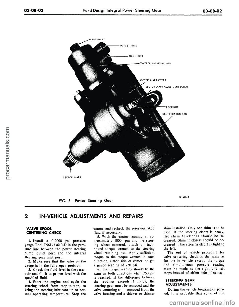
Ford Design Integral Power Steering Gear
03-08-02
-INPUT SHAFT
OUTLET PORT
INLET PORT
CONTROL VALVE HOUSING
SECTOR SHAFT COVER
SECTOR SHAFT ADJUSTMENT SCREW
LOCK NUT
IDENTIFICATION TAG
SECTOR SHAFT
FIG.
1—Power
Steering Gear
G1545- A
IN-VEH1CLE ADJUSTMENTS AND REPAIRS
VALVE SPOOL
CENTERING CHECK
1.
Install a 0-2000 psi pressure
gauge Tool T56L-33610-D in the pres-
sure line between the power steering
pump outlet port and the integral
steering gear inlet port.
2.
Make sure that the valve on the
gauge is in the fully open position.
3.
Check the fluid level in the reser-
voir and fill it to proper level with the
specified fluid.
4.
Start the engine and cycle the
steering wheel from stop-to-stop, to
bring the steering lubricant up to nor-
mal operating temperature. Stop the
engine and recheck the reservoir. Add
fluid if necessary.
5.
With the engine running at ap-
proximately 1000 rpm and the steer-
ing wheel centered, attach an inch-
pound torque wrench to the steering
wheel retaining nut. Apply sufficient
torque to the torque wrench in each
direction, either side of center, to get
a gauge reading of 250 psi.
6. The torque reading should be the
same in both directions when 250 psi
is reached. If the difference between
the readings exceeds 4 in-lbs, the
steering gear must be removed and the
valve centering shim removed from the
valve housing and a thicker or thinner
shim installed. Only one shim is to be
used. If the steering effort is heavy,
the shim thickness should be in-
creased. Shim thickness should be de-
creased if the steering effort is light to
the left.
The out of vehicle procedure for
valve centering check is the same as
for the in vehicle except the torque
and simultaneous pressure reading
must be made at the right and left
stops instead of either side of center.
STEERING GEAR
ADJUSTMENTS
During the vehicle breaking-in peri-
od, it is probable that some of theprocarmanuals.com
Page 226 of 413
04-03-06
Rear Axles — Integral Carrier Type
04-03-06
9. Install a new integral nut and
ivasher on the pinion shaft. (Apply a
small amount of lubricant on the
washer side of the nut.)
10.
Hold the flange with the tool
shown in Fig. 9 while the nut is being
tightened.
11.
Tighten the pinion shaft nut,
rotating the pinion occasionally to in-
sure proper bearing seating, (Fig. 6)
and take frequent preload readings
until the preload is at the original rec-
orded reading established in step 3.
12.
After original preload has been
reached, tighten the pinion nut slowly,
until an additional preload of 6 to 12
in-lbs has been added.
The preload should not exceed the
amount shown above, or bearing fail-
ure may result.
Under no circumstances should the
pinion nut be backed off to lessen pre-
load. If this is done, a new pinion
bearing spacer must be installed. (In
addition, the U-joint flange must
never be hammered on, or pneumatic-
-tools used.)
13.
Remove the oil seal replacer
tool from the transmission extension
housing. Install the front end of the
drive shaft on the transmission output
shaft.
14.
Connect the rear end of the
drive shaft to the axle U-joint flange,
aligning the scribe marks made on the
drive shaft end yoke and the axle U-
joint flange (Fig. 14).
15.
Check the lubricant level. Make
sure the axle is in running position.
Add whatever amount of specified lu-
bricant is required to reach the lower
edge of the filler plug hole, located in
the carrier casting or housing cover.
REMOVAL AND INSTALLATION
REAR AXLE HOUSING
REMOVAL
1.
Raise the vehicle and support it
with safety stands under the rear
frame member.
2.
Drain the lubricant from the
axle.
3.
Make scribe marks on the drive
shaft end yoke and the axle U-joint
flange to insure proper position of the
drive shaft at assembly (Fig. 14). Dis-
connect the drive shaft at the drive
pinion flange.
4.
Disconnect the lower end of the
shock absorbers.
5.
Remove the wheels, brake drums
and both axle shafts as outlined in the
foregoing Section 2.
6. Remove vent hose front vent
tube (Corbin clamp) and remove vent
tube from brake tube junction and
axle housing.
7.
Remove the hydraulic brake T-
fitting from the axle housing. Do not
open the hydraulic brake system lines.
Remove the hydraulic brake line from
its retaining clip on the axle housing.
8. Remove both axle shaft oil seals
with the tools shown in Fig. 8.
9. Remove both brake backing
plates from the axle housing and sus-
pend them above the housing with me-
chanic's wire. The hydraulic brake
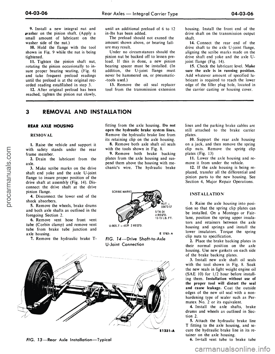
SCRIBE MARKS
5/16-24
4 REQ'D.
12-15
LB.
FT.
U-BOLT - 4529 2 REQ'D.
E 1783-A
FIG. 14—Drive Shaft-to-Axle
U-Joint
Connection
El231-A
FIG. 73—Rear Axle Installation—Typical
lines and the parking brake cables are
still attached to the brake carrier
plates.
10.
Support the rear axle housing
on a jack, and then remove the spring
clip nuts. Remove the spring clip
plates (Fig. 13)
11.
Lower the axle housing and re-
move it from under the vehicle.
12.
If the axle housing is being re-
placed, transfer all the differential and
pinion parts to the new housing. See
Section 4, Major Repair Operations.
INSTALLATION
1.
Raise the axle housing into posi-
tion so that the spring clip plates can
be installed. On a Montego or Fair-
lane,
position the spring upper insula-
tors and retainers between the axle
housing and springs and install the
lower insulators. Torque the spring
clip nuts to specification.
2.
Place the brake backing plates in
their normal position on the axle
housing. Use new gaskets on each side
of the brake backing plates.
3.
Install new axle shaft oil seals
with the tool shown in Fig. 8. Soak
the new seals in light weight engine oil
(SAE 10) for 1/2 hour before install-
ing them. Installation without use of
the proper tool will distort the seal
and cause leakage. Coat the outside
edges of the new oil seal with a non-
hardening type of sealer such as Per-
matex No. 2 or its equivalent.
4.
Install the axle shafts, brake
drums and wheels as outlined in Sec-
tion 2.
5.
Attach the hydraulic brake line
T fitting to the axle housing, and se-
cure the hydraulic brake line in its re-
tainer on the axle housing.
6. Install vent tube to brake tubeprocarmanuals.com