length FORD MUSTANG 1969 Volume One Chassis
[x] Cancel search | Manufacturer: FORD, Model Year: 1969, Model line: MUSTANG, Model: FORD MUSTANG 1969Pages: 413, PDF Size: 75.81 MB
Page 15 of 413
02-01-04
Brakes
02-01-04
ft-lb breakaway torque.
The
breaka-
way torque
is the
torque required
to
turn
the
rear wheels
the
direction
of
forward rotation with
a
torque wrench
and tool shown
in Fig. 5. The
torque
measurement must
be
made relative
to
the center line
of the
wheel.
4.
Release
the
parking brake,
and
check
to
make sure that
the
brake
shoes return
to the
fully released posi-
tion.
5.
Depress
the
parking brake pedal
to
the
third notch. Under normal
con-
ditions, this will hold
the
vehicle satis-
factorily.
6. Release
the
parking brake again,
and check
as in
step
4.
7.
If the
rear brakes
do not
fully
release, check
the
cables
for
kinks
or
binds.
Free
the
cables
as
required.
8. Lower
the
vehicle. Remove
the
torque wrench
and
tool. Install
the
wheel attaching nuts
and
torque them
to specification. Install
the
wheel
cover.
RETAINER-*^ REAR WHEEL
(CABLE ASSEMBLY
EQUALIZER
NUT
PARKING
BRAKE CABLE
AND CONDUIT
ASSEMBLY-2853
SPRING-2A651
SPRING SEAT-2A616
JAM NUT
H1631-A
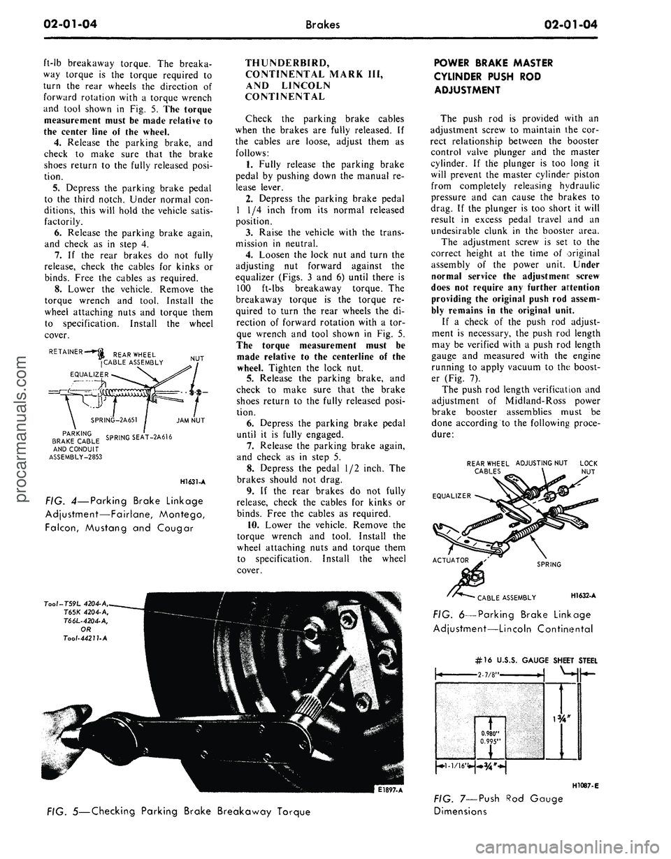
FIG. 4—Parking Brake Linkage
Adjustment—Fairlane, Montego,
Falcon,
Mustang
and
Cougar
THUNDERBIRD,
CONTINENTAL MARK
III,
AND LINCOLN
CONTINENTAL
Check
the
parking brake cables
when
the
brakes
are
fully released.
If
the cables
are
loose, adjust them
as
follows:
1.
Fully release
the
parking brake
pedal
by
pushing down
the
manual
re-
lease lever.
2.
Depress
the
parking brake pedal
1
1/4
inch from
its
normal released
position.
3.
Raise
the
vehicle with
the
trans-
mission
in
neutral.
4.
Loosen
the
lock
nut and
turn
the
adjusting
nut
forward against
the
equalizer (Figs.
3 and 6)
until there
is
100 ft-lbs breakaway torque.
The
breakaway torque
is the
torque
re-
quired
to
turn
the
rear wheels
the di-
rection
of
forward rotation with
a tor-
que wrench
and
tool shown
in Fig. 5.
The torque measurement must
be
made relative
to the
centerline
of the
wheel. Tighten
the
lock
nut.
5.
Release
the
parking brake,
and
check
to
make sure that
the
brake
shoes return
to the
fully released posi-
tion.
6. Depress
the
parking brake pedal
until
it is
fully engaged.
7.
Release
the
parking brake again,
and check
as in
step
5.
8. Depress
the
pedal
1/2
inch.
The
brakes should
not
drag.
9.
If the
rear brakes
do not
fully
release, check
the
cables
for
kinks
or
binds.
Free
the
cables
as
required.
10.
Lower
the
vehicle. Remove
the
torque wrench
and
tool. Install
the
wheel attaching nuts
and
torque them
to specification. Install
the
wheel
cover.
Tool-T59L
4204-A,
T65K
4204-A,
T66L-4204-A,
OR
Tool-4421UA
E1897-A
POWER BRAKE MASTER
CYLINDER PUSH
ROD
ADJUSTMENT
The push
rod is
provided with
an
adjustment screw
to
maintain
the cor-
rect relationship between
the
booster
control valve plunger
and the
master
cylinder.
If the
plunger
is too
long
it
will prevent
the
master cylinder piston
from completely releasing hydraulic
pressure
and can
cause
the
brakes
to
drag.
If the
plunger
is too
short
it
will
result
in
excess pedal travel
and an
undesirable clunk
in the
booster area.
The adjustment screw
is set to the
correct height
at the
time
of
original
assembly
of the
power unit. Under
normal service
the
adjustment screw
does
not
require
any
further attention
providing
the
original push
rod
assem-
bly remains
in the
original unit.
If
a
check
of the
push
rod
adjust-
ment
is
necessary,
the
push
rod
length
may
be
verified with
a
push
rod
length
gauge
and
measured with
the
engine
running
to
apply vacuum
to the
boost-
er (Fig.
7).
The push
rod
length verification
and
adjustment
of
Midland-Ross power
brake booster assemblies must
be
done according
to the
following proce-
dure:
REAR WHEEL ADJUSTING NUT
CABLES
EQUALIZER
SPRING
CABLE ASSEMBLY H1632-A
FIG. 6—Parking Brake Linkage
Adjustment—Lincoln Continental
FIG. 5—Checking Parking Brake Breakaway Torque
#16
U.J
\
0.980"
0.995"
FIG. 7—Push
Dimensions
>.S. GAUGE SHEET
i
1
STEEL
H1087-E
Rod Gaugeprocarmanuals.com
Page 16 of 413

02-01-05
Brakes
02-01-05
1.
Disconnect the master cylinder
from the booster assembly and secure
away from the booster without discon-
necting the brake tubes.
2.
Reinstall the air filter assembly
on the booster if it was removed with
the master cylinder (Fig. 8).
3.
Install and tighten the master
cylinder retaining nuts to retain the
air filter assembly securely against the
booster body and to seal the booster
bellows against air leaks.
4.
Place the gauge against the
master cylinder mounting surface of
the air filter assembly.
5.
Adjust the push rod screw to
provide a slight tension against the
inner edge of the adjustment gauge
slot. (Approximately 5 pounds of ten-
sion against the push rod is required
to assure that the push rod is firmly
seated in the booster assembly.)
6. Remove the retaining nuts from
the booster master cylinder mounting
studs.
7.
Install the master cylinder on the
brake booster and tighten the retain-
ing nuts to the specified torque.
The push rod length verification of
the Bendix power brake booster
assemblies is accomplished as follows:
1.
Disconnect the master cylinder
from the booster assembly and secure
away from the booster without discon-
necting the brake tubes.
2.
Adjust the push rod screw to
provide a slight tension against the
inner edge of the adjustment gauge
slot. (Approximately 5 pounds of ten-
sion against the push rod is required
to assure that the push rod is firmly
seated in the booster assembly.) See
Figure 8.
3.
Install the master cylinder on the
brake booster and tighten the retain-
ing nuts to the specified torque.
Do not set up side forces on the
push rod as it may break the valve
plunger.
This is an approximate adjustment
only. To verify the adjustment, look
through the make-up (rear) port of the
master cylinder when installing the
master cylinder to the booster. The
master cylinder piston should not
move more than 0.015 inch as it con-
tacts the push rod. No movement
(exact contact) is ideal.
HYDRAULIC SYSTEM BLEEDING
AND CENTRALIZING OF THE
DIFFERENTIAL VALVE
When any part of the hydraulic sys-
tem has been disconnected for repair
or replacement, air may enter the sys-
tem and cause spongy pedal action.
Bleed the hydraulic system after it has
been properly connected, to be sure
that all air is expelled.
MANUAL BLEEDING
The Lincoln Continental hydraulic
brake system is to be bled only with
pressure bleeding equipment.
The primary and secondary (front
MANIFOLD CHECK VALVE-2365 19-25 IN. LB.
TIGHTEN RETAINING NUTS
TO SECURE AIR FILTER
AGAINST BOOSTER BODY
AND BELLOWS
ADJUST PUSH ROD SCREW TO
PROVIDE A SLIGHT TENSION
(APPROXIMATELY 5 LBS.)
AGAINST THE GAUGE
PUSH ROD GAUGE
and rear) hydraulic brake systems are
individual systems and are bled separ-
ately. Bleed the longest line first on
the individual system being serviced.
During the complete bleeding opera-
tion,
DO NOT allow the reservoir to
run dry. Keep the master cylinder res-
ervoirs filled with Ford Fluid—Extra
Heavy Duty — Part Number C6AZ-
19542-A (ESA-M6C 25-A). The extra
heavy duty brake fluid is colored blue
for identification purposes. Do not
mix low temperature brake fluids with
the specified fluid during the bleeding
operations. Never re-use brake fluid
which has been drained from the hy-
draulic systems.
1.
If the master cylinder is
equipped with a bleed screw, loosen
the bleed screw. Push the brake pedal
down slowly through its full travel.
Close the bleeder fitting and return
the pedal to the fully released posi-
tion. Repeat this operation until fluid
is free of air bubbles, then tighten the
bleeder screw. Do not use the second-
ary piston stop screw, located on the
bottom of the master cylinder to bleed
the brake system. Loosening or re-
moving this screw could result in dam-
age to the secondary piston or stop
screw.
2.
To bleed the secondary (rear)
brake system, position a suitable 3/8
inch box wrench (Fig. 9) on the bleed-
er fitting on the brake wheel cylinder.
Attach a rubber drain tube to the
bleeder fitting. The end of the tube
should fit snugly around the bleeder
fitting.
APPROXIMATELY 45°
PUSH ROD ADJUSTMENT-MIDLAND-ROSS
FIG. 8—Brake Booster Push Rod Measurement
PUSH ROD ADJUSTMENT-BENDIX
H1589-A
H1300-B
. 9—Wrench for Bleeding
Brake Hydraulic System
3.
Submerge the free end of the
tube in a container partially filled with
clean brake fluid, and loosen the
bleeder fitting approximately 3/4 turn.
4.
Push the brake pedal down slow-
ly through its full travel. Close the
bleeder fitting, then return the pedal
to the full-released position. Repeat
this operation until air bubbles cease
to appear at the submerged end of the
bleeder tube.
5.
When the fluid is completely free
of air bubbles, close the bleeder fitting
and remove the bleeder tube.
6. Repeat this procedure at the
brake wheel cylinder on the oppositeprocarmanuals.com
Page 26 of 413
02-02-07
Brake System
02-02-07
ANTI-SKID CONTROL SYSTEM
RELEASE PAWL CAM PIN
RELEASE PAWL CAM LEVER
RELEASE CABLE
H
1636-
A
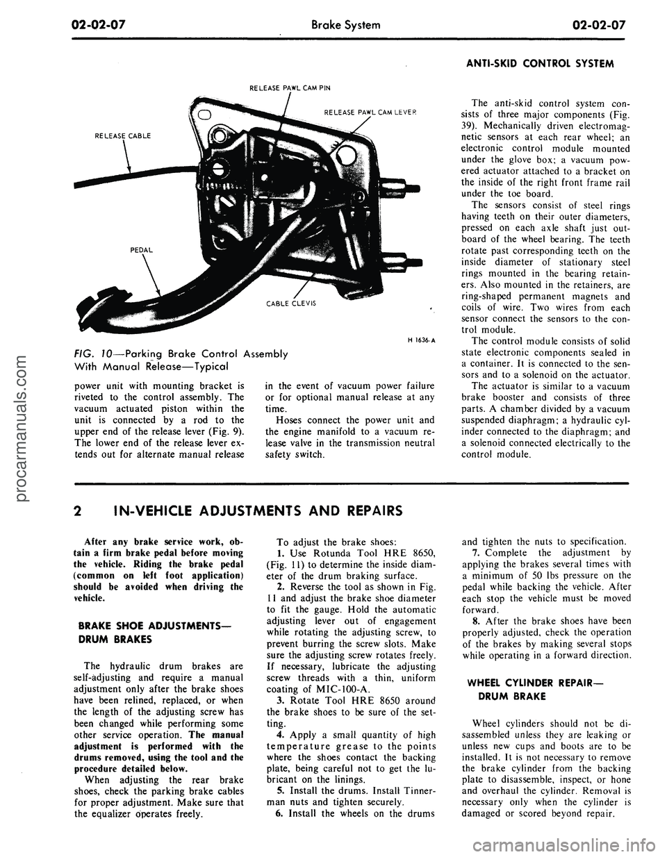
FIG. 10—Parking Brake Control Assembly
With Manual Release—Typical
power unit with mounting bracket is
riveted to the control assembly. The
vacuum actuated piston within the
unit is connected by a rod to the
upper end of the release lever (Fig. 9).
The lower end of the release lever ex-
tends out for alternate manual release
in the event of vacuum power failure
or for optional manual release at any
time.
Hoses connect the power unit and
the engine manifold to a vacuum re-
lease valve in the transmission neutral
safety switch.
The anti-skid control system con-
sists of three major components (Fig.
39).
Mechanically driven electromag-
netic sensors at each rear wheel; an
electronic control module mounted
under the glove box; a vacuum pow-
ered actuator attached to a bracket on
the inside of the right front frame rail
under the toe board.
The sensors consist of steel rings
having teeth on their outer diameters,
pressed on each axle shaft just out-
board of the wheel bearing. The teeth
rotate past corresponding teeth on the
inside diameter of stationary steel
rings mounted in the bearing retain-
ers.
Also mounted in the retainers, are
ring-shaped permanent magnets and
coils of wire. Two wires from each
sensor connect the sensors to the con-
trol module.
The control module consists of solid
state electronic components sealed in
a container. It is connected to the sen-
sors and to a solenoid on the actuator.
The actuator is similar to a vacuum
brake booster and consists of three
parts.
A chamber divided by a vacuum
suspended diaphragm; a hydraulic cyl-
inder connected to the diaphragm; and
a solenoid connected electrically to the
control module.
IN-VEHICLE ADJUSTMENTS AND REPAIRS
After any brake service work, ob-
tain a firm brake pedal before moving
the vehicle. Riding the brake pedal
(common on left foot application)
should be avoided when driving the
vehicle.
BRAKE SHOE ADJUSTMENTS—
DRUM BRAKES
The hydraulic drum brakes are
self-adjusting and require a manual
adjustment only after the brake shoes
have been relined, replaced, or when
the length of the adjusting screw has
been changed while performing some
other service operation. The manual
adjustment is performed with the
drums removed, using the tool and the
procedure detailed below.
When adjusting the rear brake
shoes,
check the parking brake cables
for proper adjustment. Make sure that
the equalizer operates freely.
To adjust the brake shoes:
1.
Use Rotunda Tool HRE 8650,
(Fig. 11) to determine the inside diam-
eter of the drum braking surface.
2.
Reverse the tool as shown in Fig.
11 and adjust the brake shoe diameter
to fit the gauge. Hold the automatic
adjusting lever out of engagement
while rotating the adjusting screw, to
prevent burring the screw slots. Make
sure the adjusting screw rotates freely.
If necessary, lubricate the adjusting
screw threads with a thin, uniform
coating of MIC-100-A.
3.
Rotate Tool HRE 8650 around
the brake shoes to be sure of the set-
ting.
4.
Apply a small quantity of high
temperature grease to the points
where the shoes contact the backing
plate, being careful not to get the lu-
bricant on the linings.
5. Install the drums. Install Tinner-
man nuts and tighten securely.
6. Install the wheels on the drums
and tighten the nuts to specification.
7.
Complete the adjustment by
applying the brakes several times with
a minimum of 50 lbs pressure on the
pedal while backing the vehicle. After
each stop the vehicle must be moved
forward.
8. After the brake shoes have been
properly adjusted, check the operation
of the brakes by making several stops
while operating in a forward direction.
WHEEL CYLINDER REPAIR-
DRUM BRAKE
Wheel cylinders should not be di-
sassembled unless they are leaking or
unless new cups and boots are to be
installed. It is not necessary to remove
the brake cylinder from the backing
plate to disassemble, inspect, or hone
and overhaul the cylinder. Removal is
necessary only when the cylinder is
damaged or scored beyond repair.procarmanuals.com
Page 27 of 413
02-02-08
Brake System
02-02-08
Tool-HRE-8650
JUST SET TO DRUM
DIAMETER HERE . . .
FIND CORRECT BRAKE
SHOE DIAMETER HERE
H1416-A
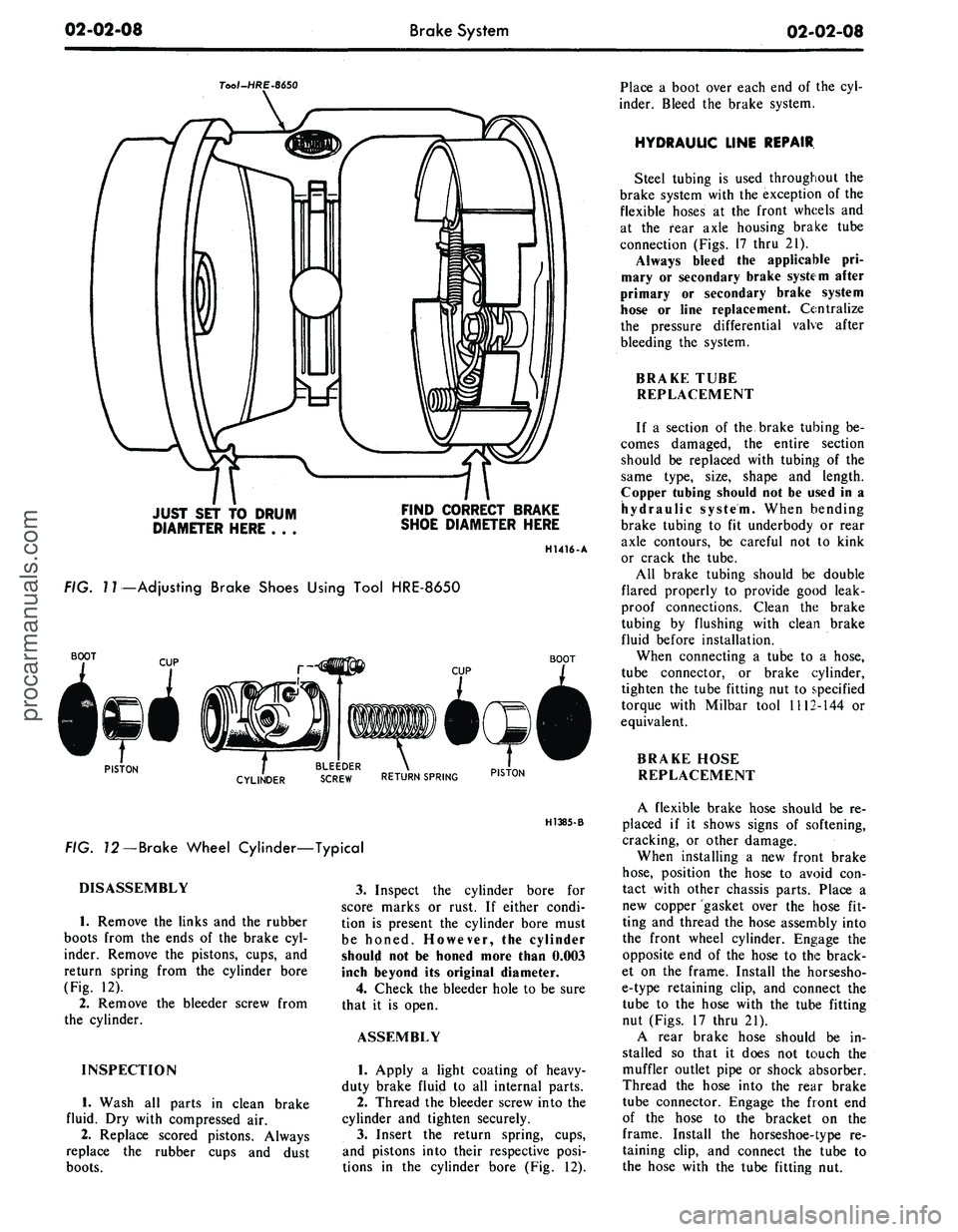
FIG.
7
7—Adjusting Brake Shoes Using Tool HRE-8650
BOOT
BOOT
PISTON
. BLEEDER .
CYLINDER
SCREW RETURN SPRING PIST0N
H1385-B
FIG. 72—Brake Wheel Cylinder—Typical
DISASSEMBLY
1.
Remove the links and the rubber
boots from the ends of the brake cyl-
inder. Remove the pistons, cups, and
return spring from the cylinder bore
(Fig. 12).
2.
Remove the bleeder screw from
the cylinder.
INSPECTION
1.
Wash all parts in clean brake
fluid. Dry with compressed air.
2.
Replace scored pistons. Always
replace the rubber cups and dust
boots.
3.
Inspect the cylinder bore for
score marks or rust. If either condi-
tion is present the cylinder bore must
be honed. However, the cylinder
should not be honed more than 0.003
inch beyond its original diameter.
4.
Check the bleeder hole to be sure
that it is open.
ASSEMBLY
1.
Apply a light coating of heavy-
duty brake fluip! to all internal parts.
2.
Thread the bleeder screw into the
cylinder and tighten securely.
3.
Insert the return spring, cups,
and pistons into their respective posi-
tions in the cylinder bore (Fig. 12).
Place a boot over each end of the cyl-
inder. Bleed the brake system.
HYDRAULIC LINE REPAIR
Steel tubing is used throughout the
brake system with the exception of the
flexible hoses at the front wheels and
at the fear axle housing brake tube
connection (Figs. 17 thru 21).
Always bleed the applicable pri-
mary or secondary brake system after
primary or secondary brake system
hose or line replacement. Centralize
the pressure differential valve after
bleeding the system.
BRAKE TUBE
REPLACEMENT
If a section of the brake tubing be-
comes damaged, the entire section
should be replaced with tubing of the
same type, size, shape and length.
Copper tubing should not be used in a
hydraulic system. When bending
brake tubing to fit underbody or rear
axle contours, be careful not to kink
or crack the tube.
All brake tubing should be double
flared properly to provide good leak-
proof connections. Clean the brake
tubing by flushing with clean brake
fluid before installation.
When connecting a tube to a hose,
tube connector, or brake cylinder,
tighten the tube fitting nut to specified
torque with Milbar tool 1112-144 or
equivalent.
BRAKE HOSE
REPLACEMENT
A flexible brake hose should be re-
placed if it shows signs of softening,
cracking, or other damage.
When installing a new front brake
hose,
position the hose to avoid con-
tact with other chassis parts. Place a
new copper gasket over the hose fit-
ting and thread the hose assembly into
the front wheel cylinder. Engage the
opposite end of the hose to the brack-
et on the frame. Install the horsesho-
e-type retaining clip, and connect the
tube to the hose with the tube fitting
nut (Figs. 17 thru 21).
A rear brake hose should be in-
stalled so that it does not touch the
muffler outlet pipe or shock absorber.
Thread the hose into the rear brake
tube connector. Engage the front end
of the hose to the bracket on the
frame. Install the horseshoe-type re-
taining clip, and connect the tube to
the hose with the tube fitting nut.procarmanuals.com
Page 29 of 413
02-02-10
Brake System
02-02-10
brake adjustment then connect the
parking brake cable to the parking
brake lever (Fig. 8).
4.
Install the shoe guide (anchor
pin) plate on the anchor pin when so
equipped.
5.
Place the cable eye over the an-
chor pin with the crimped side toward
the backing plate.
6. Install the primary shoe to an-
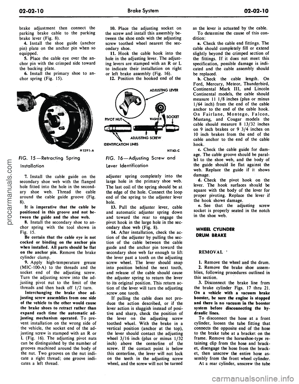
chor spring (Fig. 15).
H1391-A
FIG. 75—Retracting Spring
Installation
7.
Install the cable guide on the
secondary shoe web with the flanged
hole fitted into the hole in the second-
ary shoe web. Thread the cable
around the cable guide groove (Fig.
8).
It
is
imperative that
the
cable
be
positioned
in
this groove
and not be-
tween
the
guide
and the
shoe
web.
8.
Install the secondary shoe to an-
chor spring with the tool shown in
Fig. 15.
Be certain that
the
cable
eye is not
cocked
or
binding
on the
anchor
pin
when installed.
All
parts should
be
flat
on
the
anchor
pin.
Remove
the
brake
cylinder clamp.
9. Apply high-temperature grease
(MIC-100-A) to the threads and the
socket end of the adjusting screw.
Turn the adjusting screw into the ad-
justing pivot nut to the limit of the
threads and then back off 1/2 turn.
Interchanging
the
brake shoe
ad-
justing screw assemblies from
one
side
of
the
vehicle
to the
other would cause
the brake shoes
to
retract rather than
expand each time
the
automatic
ad-
justing mechanism operated.
To pre-
vent installation on the wrong side of
the vehicle, the socket end of the ad-
justing screw is stamped with an R or
L (Fig. 16). The adjusting pivot nuts
can be distinguished by the number of
grooves machined around the body of
the nut. Two grooves on the nut indi-
cate a right thread; one groove indi-
cates a left thread.
10.
Place the adjusting socket on
the screw and install this assembly be-
tween the shoe ends with the adjusting
screw toothed wheel nearest the sec-
ondary shoe.
11.
Hook the cable hook into the
hole in the adjusting lever. The adjust-
ing levers are stamped with an R or L
to indicate their installation on right
or left brake assembly (Fig. 16).
12.
Position the hooked end of the
ADJUSTING LEVER
IDENTIFICATION LINES
H1143-C
FIG. 16—Adjusting Screw
and
Lever Identification
adjuster spring completely into the
large hole in the primary shoe web.
The last coil of the spring should be at
the edge of the hole. Connect the loop
end of the spring to the adjuster lever
hole.
13.
Pull the adjuster lever, cable
and automatic adjuster spring down
and toward the rear to engage the
pivot hook in the large hole in the sec-
ondary shoe web (Fig. 8).
14.
After installation, check the ac-
tion of the adjuster by pulling the sec-
tion of the cable between the cable
guide and the anchor pin toward the
secondary shoe web far enough to lift
the lever past a tooth on the adjusting
screw wheel. The lever should snap
into position behind the next tooth,
and release of the cable should cause
the adjuster spring to return the lever
to its original position. This return ac-
tion of the lever will turn the adjusting
screw.one tooth.
If pulling the cable does not pro-
duce the action described, or if the
lever action is sluggish instead of posi-
tive and sharp, check the position of
the lever on the adjusting screw
toothed wheel. With the brake in a
vertical position (anchor at the top),
the lever should contact the adjusting
wheel 3/16 inch (plus or minus 1/32
inch) above the centerline of the
screw. If the contact point is below
this centerline, the lever will not lock
on the teeth in the adjusting screw
wheel, and the screw will not be turned
as the lever is actuated by the cable.
To determine the cause of this con-
dition:
a. Check the cable end fittings. The
cable should completely fill or extend
slightly beyond the crimped section of
the fittings. If it does not meet this
specification, possible damage is indi-
cated and the cable assembly should
be replaced.
b.
Check the cable length. On
Ford, Mercury, Meteor, Thunderbird,
Continental Mark III, and Lincoln
Continental models, the cable should
measure 11 1/8 inches (plus or minus
1/64 inch) from the end of the cable
anchor to the end of the cable hook.
On Fairlane, Montego, Falcon,
Mustang, and Cougar models the
cable should measure 8 13/32 inches
on 9 inch brakes or 9 3/4 inches on
10 inch brakes from the end of the
cable anchor to the end of the cable
hook.
c. Check the cable guide for dam-
age.
The cable groove should be paral-
lel to the shoe web, and the body of
the guide should lie flat against the
web.
Replace the guide if it shows
damage.
d. Check the pivot hook on the
lever. The hook surfaces should be
square with the body of the lever for
proper pivoting. Replace the lever if
the hook shows damage.
e. See that the adjusting; screw
socket is properly seated in the notch
in the shoe web.
WHEEL CYLINDER
DRUM BRAKE
REMOVAL '
1.
Remove the wheel and the drum.
2.
Remove the brake shoe assem-
blies,
following procedures outlined in
this section.
3.
Disconnect the brake line from
the brake cylinder Figs. 17 thru 21.
On
a
vehicle with
a
vacuum brake
booster,
be
sure
the
engine
is
stopped
and there
is no
vacuum
in the
booster
system before disconnecting
the hy-
draulic lines.
To disconnect the hose at a front
cylinder, loosen the tube fitting that
connects the opposite end of the hose
to the brake tube at a bracket on the
frame. Remove the horseshoe-type re-
taining clip from the hose and brack-
et, disengage the hose from the brack-
et, then unscrew the entire hose as-
sembly from the front wheel cylinder.
At a rear cylinder, unscrew the tubeprocarmanuals.com
Page 40 of 413
02-02-21
Brake System
02-02-21
INSTALLATION
CLUTCH ASSIST
SPRING
MASTER CYLINDER
2140
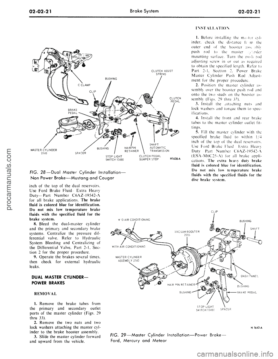
FIG. 28 —Dual Master Cylinder Installation—
Non Power Brake—Mustang and Cougar
inch of the top of the dual reservoirs.
Use Ford Brake Fluid- Extra Heavy
Duty-Part Number C6AZ-19542-A
for all brake applications. The brake
fluid is colored blue for identification.
Do not mix low temperature brake
fluids with the specified fluid for the
brake system.
8. Bleed the dual-master cylinder
and the primary and secondary brake
systems. Centralize the pressure dif-
ferential valve. Refer to Hydraulic
System Bleeding and Centralizing of
the Differential Valve, Part 2-1, Sec-
tion 2 for the proper procedure.
9. Operate the brakes several times,
then check for external hydraulic
leaks.
DUAL MASTER CYLINDER-
POWER BRAKES
REMOVAL
1.
Remove the brake tubes from
the primary and secondary outlet
ports of the master cylinder (Figs. 29
thru 33).
2.
Remove the two nuts and two
lock washers attaching the master cyl-
inder to the brake booster assembly.
3.
Slide the master cylinder forward
and upward from the vehicle.
SHAFT
AUTOMATIC
TRANSMISSION
CLUTCH PEDAL
BUMPER STOP
H1638-A
1.
Before installing the mater cyl-
inder, check the distance t; m the
outer end of the booster ass;. ,ihi\
push rod to the master .>',nder
mounting surface. Turn the nu->h rod
adjusting screw in or out as required
to obtain the specified length. Refer to
Part 2-1, Section 2. Power Brake
Master Cylinder Push Rod Adjust-
ment for the proper procedure.
2.
Position the master cylinder as-
sembly over the booster push rod and
onto the two studs on the booster as-
sembly (Figs. 29 thru 37).
3.
Install the attaching nuts and
lock washers and torque them to spec-
ifications.
4.
Install the front and rear brake
tubes to the master cylinder outlet fit-
tings.
5.
Fill the master cylinder with the
specified brake fluid to within 1/4
inch of the top o\ the dual reservoirs.
Use Ford Brake Fluid Fxtra Heavy
Duty Part Number C6AZ-19542-A
(ESA-M6C25-A) for all brake appli-
cations. The extra htaw duty brake
fluid is colored blue for identification.
Do not mix low temperature brake
fluids with the specified fluids for the
disc brake svstem.
CLIP
W
'0 AIR CONDITIONING
BUSHING
SHAFT
BUSHING
BRAKE PEDAL
SPACER
H 1642-A
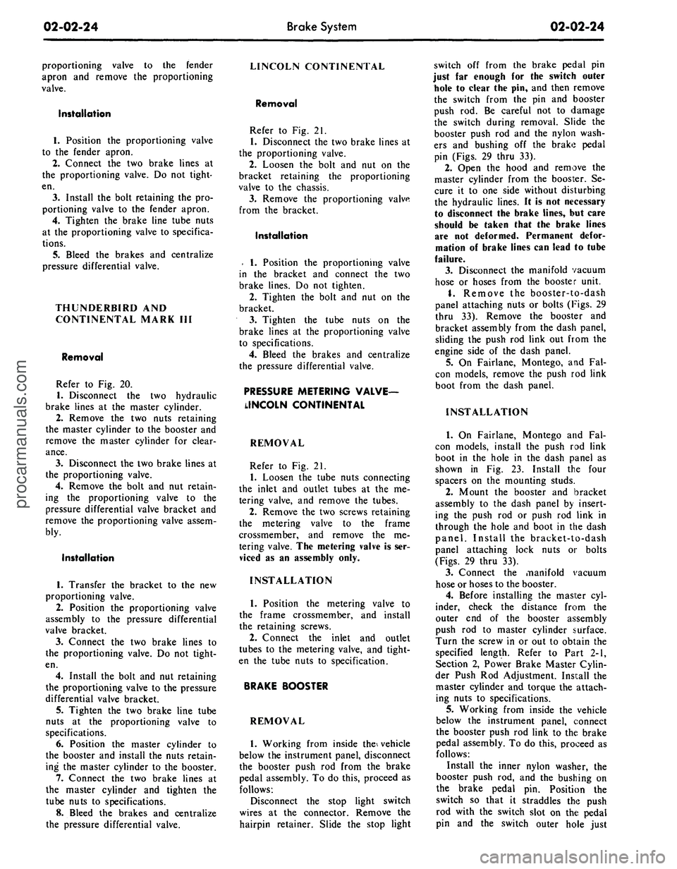
FIG. 29—Master Cylinder Installation-
Ford,
Mercury and Meteor
-Power Brake-procarmanuals.com
Page 43 of 413
02-02-24
Brake
System
02-02-24
proportioning valve to the fender
apron and remove the proportioning
valve.
Installation
1.
Position the proportioning valve
to the fender apron.
2.
Connect the two brake lines at
the proportioning valve. Do not tight-
en.
3.
Install the bolt retaining the pro-
portioning valve to the fender apron.
4.
Tighten the brake line tube nuts
at the proportioning valve to specifica-
tions.
5.
Bleed the brakes and centralize
pressure differential valve.
THUNDERBIRD AND
CONTINENTAL MARK III
Removal
Refer to Fig. 20.
1.
Disconnect the two hydraulic
brake lines at the master cylinder.
2.
Remove the two nuts retaining
the master cylinder to the booster and
remove the master cylinder for clear-
ance.
3.
Disconnect the two brake lines at
the proportioning valve.
4.
Remove the bolt and nut retain-
ing the proportioning valve to the
pressure differential valve bracket and
remove the proportioning valve assem-
bly.
Installation
1.
Transfer the bracket to the new
proportioning valve.
2.
Position the proportioning valve
assembly to the pressure differential
valve bracket.
3.
Connect the two brake lines to
the proportioning valve. Do not tight-
en.
4.
Install the bolt and nut retaining
the proportioning valve to the pressure
differential valve bracket.
5.
Tighten the two brake line tube
nuts at the proportioning valve to
specifications.
6. Position the master cylinder to
the booster and install the nuts retain-
ing the master cylinder to the booster.
7.
Connect the two brake lines at
the master cylinder and tighten the
tube nuts to specifications.
8. Bleed the brakes and centralize
the pressure differential valve.
LINCOLN CONTINENTAL
Removal
Refer to Fig. 21.
1.
Disconnect the two brake lines at
the proportioning valve.
2.
Loosen the bolt and nut on the
bracket retaining the proportioning
valve to the chassis.
3.
Remove the proportioning valve
from the bracket.
Installation
- 1. Position the proportioning valve
in the bracket and connect the two
brake lines. Do not tighten.
2.
Tighten the bolt and nut on the
bracket.
3.
Tighten the tube nuts on the
brake lines at the proportioning valve
to specifications.
4.
Bleed the brakes and centralize
the pressure differential valve.
PRESSURE METERING VALVE—
LINCOLN CONTINENTAL
REMOVAL
Refer to Fig. 21.
1.
Loosen the tube nuts connecting
the inlet and outlet tubes at the me-
tering valve, and remove the tubes.
2.
Remove the two screws retaining
the metering valve to the frame
crossmember, and remove the me-
tering valve. The metering valve is ser-
viced as an assembly only.
INSTALLATION
1.
Position the metering valve to
the frame crossmember, and install
the retaining screws.
2.
Connect the inlet and outlet
tubes to the metering valve, and tight-
en the tube nuts to specification.
BRAKE BOOSTER
REMOVAL
1.
Working from inside the\ vehicle
below the instrument panel, disconnect
the booster push rod from the brake
pedal assembly. To do this, proceed as
follows:
Disconnect the stop light switch
wires at the connector. Remove the
hairpin retainer. Slide the stop light
switch off from the brake pedal pin
just far enough for the switch outer
hole to clear the pin, and then remove
the switch from the pin and booster
push rod. Be careful not to damage
the switch during removal. Slide the
booster push rod and the nylon wash-
ers and bushing off the brake pedal
pin (Figs. 29 thru 33).
2.
Open the hood and remove the
master cylinder from the booster. Se-
cure it to one side without disturbing
the hydraulic lines. It is not necessary
to disconnect the brake lines, but care
should be taken that the brake lines
are not deformed. Permanent defor-
mation of brake lines can lead to tube
failure.
3.
Disconnect the manifold vacuum
hose or hoses from the booster unit.
4.
Remove the booster-to-dash
panel attaching nuts or bolts (Figs. 29
thru 33). Remove the booster and
bracket assembly from the dash panel,
sliding the push rod link out from the
engine side of the dash panel.
5.
On Fairlane, Montego, and Fal-
con models, remove the push rod link
boot from the dash panel.
INSTALLATION
1.
On Fairlane, Montego and Fal-
con models, install the push rod link
boot in the hole in the dash panel as
shown in Fig. 23. Install the four
spacers on the mounting studs.
2.
Mount the booster and bracket
assembly to the dash panel by insert-
ing the push rod or push rod link in
through the hole and boot in the dash
panel. Install the bracket-to-dash
panel attaching lock nuts or bolts
(Figs.
29 thru 33).
3.
Connect the manifold vacuum
hose or hoses to the booster.
4.
Before installing the master cyl-
inder, check the distance from the
outer end of the booster assembly
push rod to master cylinder surface.
Turn the screw in or out to obtain the
specified length. Refer to Part 2-1,
Section 2, Power Brake Master Cylin-
der Push Rod Adjustment. Install the
master cylinder and torque the attach-
ing nuts to specifications.
5.
Working from inside the vehicle
below the instrument panel, connect
the booster push rod link to the brake
pedal assembly. To do this, proceed as
follows:
Install the inner nylon washer, the
booster push rod, and the bushing on
the brake pedal pin. Position the
switch so that it straddles the push
rod with the switch slot on the pedal
pin and the switch outer hole justprocarmanuals.com
Page 53 of 413
02-02-34
Brake System
02-02-34
strument panel. Install the lower con-
trol panel retaining screws.
8. Install the windshield wiper con-
trol bezel and knob.
9. Working in the engine compart-
ment connect the wire harness and
vacuum hoses to the Automatic Tem-
perature Control box.
10.
Connect the battery cable.
11.
Raise the vehicle on a hoist.
12.
Connect the cable ball to the
equalizer and install the equalizer
lever return ^spring.
13.
Adjust the parking brake cable
tension.
14.
Lower the vehicle.
PARKING BRAKE ACTUATOR—
TO CONTROL CABLE
FORD, MERCURY
AND METEOR
Removed
1.
Raise the vehicle on a hoist.
2.
Loosen the actuator lever to
equalizer cable adjusting nut at the
equalizer (Fig. 34).
3.
Disconnect the cable ball from
the clevis on the actuator lever.
4.
Remove spring clip that retains
the cable to the frame.
5.
From inside of passenger com-
partment, remove spring clip that re-
tains the cable to the parking brake
control. Disconnect the cable ball
from the control assembly.
6. Remove the cable assembly from
the vehicle.
Installation
1.
Position the cable through the
provided openings and in the approxi-
mate final installation position.
2.
Install the hairpin retainer on the
cable at the frame crossmember.
3.
Connect the ball end of the cable
to the parking brake control. Install
the cable-to-control hairpin retaining
clip.
4.
Position the cable seal at the
dash panel, and slide the retaining clip
upward to seal the cable at the dash
opening.
5.
Connect the ball end of the cable
to the clevis on the actuator lever.
6. Adjust the parking brake (Part
2-1,
Section 2).
7.
Lower vehicle on hoist.
THUNDERBIRD AND
CONTINENTAL MARK III
Removal
Refer to Fig. 37.
1.
Partially raise the vehicle.
2.
Back off the adjusting nut at the
equalizer to relieve the tension on the
cable.
3.
Remove the spring at the actua-
tor lever and disconnect the control
cable from the clevis on the lever.
4.
Remove the clip retaining the
control cable assembly to
thq*.
frame
bracket. B
5.
Attach a length of wire to the
control cable.
6. Working inside the vehicle re-
move two screws retaining the left
scuff plate.
7.
Remove one screw and remove
the left cowl side trim panel.
8. Remove the two screws retaining
the left air duct to the inner panel and
remove the air duct.
9. Remove the two screws retaining
the dimmer switch and position the
dimmer switch back out of the way.
10.
Remove the clip retaining the
cable assembly to the control and re-
move the cable ball from the control
clevis.
11.
Pull the cable up through the
opening in the dash panel and remove
the cable from the length of wire.
Installation
1.
Attach the cable to the length of
wire and pull the cable down through
the opening in the dash panel.
2.
Position the upper end of the
control cable to the control. Connect
the cable ball to the control clevis and
install the clip retaining the cable
housing to the control.
3.
Remove the length of wire from
the cable assembly and position the
cable in the frame bracket. Install the
retainer,
4.
Connect the cable ball to the
clevis on the actuator lever and install
the actuator lever spring.
5.
Adjust the parking brake.
6. Reposition the dimmer switch
and install the retaining screws.
7.
Position the air duct to the inner
panel and install the retaining screws.
& Position the cowl side trim panel
and install the retaining screw.
9. Install the two screws in the
scuff plate.
PARKING BRAKE
EQUALIZER TO CONTROL
CABLE
FAIRLANE, MONTEGO
AND FALCON
Removal
Refer to Fig. 35.
1.
Make certain the parking brake
is fully released.
2.
Raise the vehicle on a hoist. Re-
move the two nuts that attach the
cable to the equalizer. Remove the
equalizer, spring seat and spring.
3.
Remove the hairpin retainer
holding the cable assembly to i:he body
bracket and remove the cable from
the slot in the bracket.
4.
Lower the vehicle partially.
5.
Remove the hairpin retainer
which retains the cable assembly to
the control.
6. Remove the cable bolt retaining
clip from the control clevis and dis-
connect the cable ball from the clevis.
7.
Pull the cable down through the
opening in the floor pan and frame
side rail.
Installation
1.
Route the new cable through
the frame side rail and up through
the opening in the floor pan. Pull the
cable up into position.
2.
Connect the cable ball in the con-
trol clevis.
3.
Insert the cable housing into
the control and install the hairpin re-
tainer.
4.
Raise the vehicle.
5.
Position the cable in the body
bracket and install the hairpin re-
tainer.
6. Position the spring, spring re-
tainer and equalizer on the cable and
install the two nuts.
7.
Adjust the parking brake.
MUSTANG AND COUGAR
Removal
Refer to Fig. 36.
1.
Make certain the parking brake
is fully released.
2.
Raise the vehicle on a hoist. Re-
move the two nuts that attach the
cable to the equalizer. Remove the
equalizer spring seat and spring.
3.
Remove the hairpin retainer
holding the cable assembly to the
body bracket and pull the cable out
of the side rail access holes.procarmanuals.com
Page 72 of 413
03-01-07
Suspension — Steering, Wheels And Tires — General Service
03-01-07
upper arm shaft to the frame member
(Fig. 3, Part 3-2).
2.
Loosen the arm shaft attaching
bolts,
raise the front end of the vehicle
and lower it again. This will break the
arm shaft loose from the frame mem-
ber.
3.
With a pry bar, move the arm
shaft back into alignment with the
chalk marks made in Step 1, and
tighten the shaft attaching bolts. The
bolts should be tightened just enough
to hold the shaft in position without
preventing its being moved with the
pry bar.
Caster
1.
With the aid of a pry bar, move
the shaft in or out, as required, to
meet specifications. A movement of
approximately 3 /32 inch at either the
front or rear bolt location will change
the caster 1/2 degree. Inboard move-
ment of the front bolt, or outboard
movement of the rear bolt, will change
caster in the negative direction. Out-
board movement of the front bolt, or
inboard movement of the rear bolt,
will change caster in the positive di-
rection.
2.
When the caster is correct, tor-
que the shaft attaching bolts to speci-
fication and recheck the caster and
camber to insure that the readings
have not changed.
Camber
TURN DOWNWARD TO
INCREASE ROD LENGTH
TURN UPWARD
TO DECREASE
ROD LENGTH
TURN
DOWNWARD
TO DECREASE
ROD LENGTH
TURN UPWARD TO
INCREASE ROD LENGTH
LEFT-HAND SLEEVE
RIGHT-HAND SLEEVE
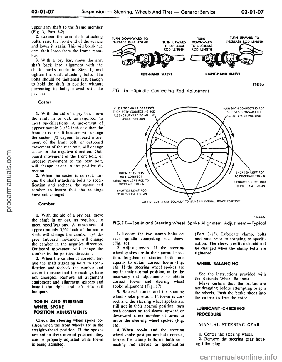
FIG. 16—Spindle Connecting Rod Adjustment
WHEN TOE-IN IS CORRECT
TURN BOTH CONNECTING ROD
SLEEVES UPWARD TO ADJUST
SPOKE POSITION
F1433-A
i URN BOTH CONNECTING ROD
SLEEVES DOWNWARD TO
ADJUST SPOKE POSITION
WHEN TOE-IN IS
NOT CORRECT
LENGTHEN LEFT ROD TO
INCREASE TOE-IN
SHORTEN RIGHT ROD
TO DECREASE TOE-IN
SHORTEN LEFT ROD
TO DECREASE TOE-IN
LENGHTEN RIGHT ROD
TO INCREASE TOE-IN
ADJUST BOTH RODS EQUALLY TO MAINTAIN NORMAL SPOKE POSITION
1.
With the aid of a pry bar, move
the shaft in or out, as required, to
meet specifications. A movement of
approximately 3/64 inch of the entire
shaft will change the camber 1/4 de-
gree.
Inboard movement will change
the camber in the negative direction.
Outboard movement will change the
camber in the positive direction.
2.
When the camber is correct, tor-
que the shaft attaching bolts to speci-
fication and recheck the camber and
caster to insure that the readings have
not changed. Remove all alignment
equipment and alignment spacers and
install the right and left side rail
bumpers.
TOE-IN AND STEERING
WHEEL SPOKE
POSITION ADJUSTMENTS
Check the steering wheel spoke po-
sition when the front wheels are in the
straight-ahead position. If the spokes
are not in their normal position, they
can be properly adjusted while toe-in
is being adjusted.
F1434-
A
f/G.77—Toe-in and Steering Wheel Spoke Alignment Adjustment—Typical
1.
Loosen the two ciamp bolts or
each spindle connecting rod sleeve
(Fig. 16).
2.
Adjust toe-in. If the steering
wheel spokes are in their normal posi-
tion, lengthen or shorten both rods
equally to obtain correct toe-in (Fig.
16).
If the steering wheel spokes are
not in their normal position, make the
necessary rod adjustments to obtain
correct toe-in and steering wheel
spoke alignment (Fig. 17).
3.
Recheck toe-in and the steering
wheel spoke position. If toe-in is cor-
rect and the steering wheel spokes are
still not in their normal position, turn
both connecting rod sleeves upward or
downward same number of turns to
move the steering wheel spokes (Fig.
16).
4.
When toe-in and the steering
wheel spoke position are both correct,
torque the clamp bolts on both con-
necting rod sleeves to specification
(Part 3-13). Lubricate clamp, bolts
and nuts prior to torquing to specifi-
cation. The sleeve position should not
be changed when the clamp bolts are
tightened.
WHEEL BALANCING
See the instructions provided with
the Rotunda Wheel Balancer.
Make certain that the brakes are
not dragging before attempting to spin
the wheels. Push the brake shoes into
the caliper to free the rotor.
LUBRICANT CHECKING
PROCEDURE
MANUAL STEERING GEAR
1.
Center the steering wheel.
2.
Remove the steering gear hous-
ing filler plug.procarmanuals.com
Page 182 of 413
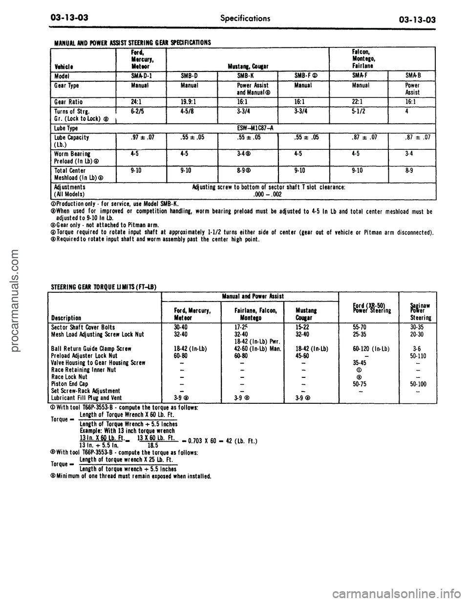
03-13-03
Specifications
03-13-03
MANUAL AND POWER
Vehicle
Model
Gear Type
Gear Ratio
Turns of
Strg.
Gr. (Lock to Lock)
®
Lube Type
Lube Capacity
(Lb.)
Worm Bearing
Preload (In Lb)®
Total Center
Meshload(lnLb)®
Adjustments
(All Models)
ASSIST STEERING GEAR SPECIFICATIONS
Ford,
Mercury,
Meteor
SM/VD-1
Manual
24:1
6-2/5
.97
±
.07
4-5
9-10
SMB-D
Manual
19.9:1
4-5/8
.55
±
.05
4-5
9-10
Adjusting
Mustang, Cougar
SMBK
Power Assist
and Manual®
16:1
3-3/4
ESW-M1C87-A
.55
±
.05
3-4®
8-9®
screw to bottom
of
sector
.000 -.002
SMB-F®
Manual
16:1
3-3/4
.55
±
.05
4-5
9-10
shaft T slot clearance:
Falcon,
Mont ego,
Fairlane
SMA-F
Manual
22:1
5-1/2
.87
±
.07
4-5
9-10
SMA-B
Power
Assist
16:1
4
.87
±
.07
3-4
8-9
©Production only
-
for service, use Model SMB-K.
®When used
for
improved
or
competition handling, worm bearing preload must
be
adjusted
to
4-5
In
Lb and total center meshload must
be
adjusted to 9-10 In Lb.
®Gear only
-
not attached to Pitman arm.
0Torque required
to
rotate input shaft
at
approximately 1-1/2 turns either side
of
center (gear
out of
vehicle
or
Pitman arm disconnected).
©Requiredto rotate input shaft and worm assembly past
the
center high point.
STEERING GEAR TORQUE UMITS(FT-LB)
Description
Sector Shaft Cover Bolts
Mesh Load Adjusting Screw Lock Nut
Ball Return Guide Clamp Screw
Preload Adjuster Lock Nut
Valve Housing
to
Gear Housing Screw
Race Retaining Inner Nut
Race Lock Nut
Piston End Cap
Set Screw-Rack Adjustment
Lubricant Fill Plug and Vent
Manual and Power Assist
Ford,
Mercury,
Meteor
30-40
32-40
18-42 (In-Lb)
60-80
3-9®
Fairlane, Falcon,
Montego
17-2?
32-40
18-42 (In-Lb) Pwr.
42-60 (In-Lb) Man.
60-80
3-9®
Mustang
Cougar
15-22
32-40
18-42 (In-Lb)
45-60
3-9®
Power steering
55-70
25-35
60-120 (In-Lb)
35-45
(D
®
50-75
Steering
30-35
20-30
3-6
50-110
50-100
® With tool T66P-3553-B
•
compute the torque as follows:
Length
of
Torque Wrench
X
60 Lb.
Ft.
°rque
"
Length
of
Torque Wrench
+
5.5 Inches
Example: With 13 inch torque wrench
13ln.
X
60 Lb. Ft. 13
X
60 Lb.
Ft.
13
In.
+
5.5 In.
18.5
®With tool T66P-3553-B
•
compute the torque as follows:
Length
of
torque wrench
X
25 Lb.
Ft.
Length of torque wrench
+
5.5 Inches
©Minimum
of
one thread must remain exposed when installed.
-0.703 X60- 42 (Lb.
Ft.)procarmanuals.com