reset FORD MUSTANG 1969 Volume One Chassis
[x] Cancel search | Manufacturer: FORD, Model Year: 1969, Model line: MUSTANG, Model: FORD MUSTANG 1969Pages: 413, PDF Size: 75.81 MB
Page 37 of 413
02-02-18
Brake System
02-02-18
the brake hose connector
and
bracket
assembly.
3.
Remove
the two
bolts retaining
the brake hose bracket
and
caliper
as-
sembly
to the
spindle. Take care
to
avoid loosening
the
bridge bolts that
hold
the two
halves
of the
caliper
to-
gether.
4.
Lift
the
caliper assembly
off the
rotor
and
place
it on the
bench.
Installation
1.
If the
caliper assembly
is to be
replaced, transfer
the
steel tubing
and
the bleeder screw
to the new
caliper.
2.
Position
the
caliper assembly
on
the rotor,
and
mate
the
mounting bolt
holes
in the
caliper with those
in the
spindle.
It may be
necessary
to
push
the caliper pistons into
the
cylinder
bores
to
obtain clearance between
the
shoe
and
lining assembly
and the
rotor.
The
shoe
and
lining assemblies
should
be
seated properly
on the
bridges.
3.
Install
the
caliper
to
spindle
re-
taining bolts
and
torque them
to
spec-
ification. Check
to
insure that
the
rotor runs squarely
and
centrally
be-
tween
the two
halves
of the
caliper.
These should
be
approximately 0.090-
0.120 inch clearance between
the
cali-
per
and the
rotor outside diameter
(Fig.
6).
4.
Position
the
steel transfer tube
brake hose bracket
and
caliper assem-
bly
to the
spindle. Install
the
retaining
bolts then torque them
to
specifica-
tion.
5.
Connect
the
front wheel steel
transfer tube from
the
caliper
to the
front brake hose connector. Check
the
hose
for
proper installation
(Fig. 21).
6. Bleed
the
brake system
and cen-
tralize
the
differential valve
as out-
lined
in
Part
2-1.
Check
the
master
cylinder fluid level
and add the
speci-
fied fluid,
as
required. Pump
the
brake pedal several times
to
actuate
the piston seals
and to
position
the
shoe
and
lining assemblies.
7.
Install
the
wheel
and
tire assem-
bly
and the
wheel cover.
8. Road test
the
vehicle.
DISC BRAKE SHOE
AND
LINING
ALL MODELS EXCEPT
LINCOLN CONTINENTAL
Removal
1.
Remove
the
wheel
and
tire from
the
hub and
rotor assembly.
2.
Remove
the
caliper from
the ve-
hicle following
the
procedures outlined
under Disc Brake Caliper Assembly.
3.
To
facilitate removal
of the
cali-
per assemblies,
the
piston
may
have
to
be pushed into
its
bore. Apply
a
steady inward pressure against
the
inner shoe
and
lining assembly. Main-
tain
the
pressure
for at
least
a
minute.
4.
Slide
the two
outer shoe retain-
ing clips
off the
retaining pins
(Fig.
23).
5.
Remove
the two
retaining pins
from
the
outer shoe, then remove
the
shoe from
the
stationary caliper.
6. Slide
the
inner brake shoe
out-
ward until
it is
free
of the
hold-down
springs, then remove
the
brake shoe.
7.
Remove
the
caliper locating pins
and stabilizer attaching bolts, then
re-
move
and
discard
the
stabilizer
or sta-
bilizers.
8. Remove
the
locating
pin
insula-
tors from
the
anchor plate.
Installation
When installing
new
shoes
and lin-
ings
it
will
be
necessary
to
force
the
piston
to the
bottom
of its
bore.
Apply sufficient pressure
to
overcome
the grip
of the
piston seal
on the pis-
ton.
1.
Install
new
caliper locating
pin
insulators
in the
anchor plate.
2.
Position
the
caliper assembly
in
the anchor plate.
3.
Position
the new
stabilizer
or
stabilizers
and
install
the
caliper locat-
ing pins
to
engage approximately four
threads.
If
the
caliper locating pins
are
rust-
ed
or
corroded they should
be re-
placed.
Apply water
or
isopropyl alcohol
to
the caliper locating pins before instal-
lation.
Oil or
grease must
not be
used
on
the
locating pins.
4.
Position
the
outer brake shoe
on
the caliper
and
install
the two
retain-
ing pins
and
clips.
5.
Install
the
inner brake shoe
so
that
the
ears
of
shoe
are on top of the
anchor plate bosses
and
under
the
shoe hold-down springs.
6. Position
the
shoe
and
lining
assemblies
so
that
the
caliper assem-
bly
can be
placed over
the
rotor.
Ro-
tate
a
hammer handle between
the lin-
ings
to
reset
the
stabilizers.
7.
Install
the
caliper assembly over
the rotor
and on the
spindle. Install
the
two
caliper attaching bolts,
and
torque them
to
specifications.
The
upper bolt must
be
tightened first.
In-
stall
the
safety wire
and
twist
the
ends
at least five turns. Push
the
wire ends
against
the
spindle
to
avoid interfer-
ence with
the
brake hose
and the
steering stop.
8. With moderate pressure applied
to
the
brake pedal, torque
the
stabiliz-
er attaching screws
and
caliper locat-
ing pins
to
specification.
LINCOLN CONTINENTAL
Removal
1.
Remove
the
wheel
and
tire
as-
sembly from
the hub and
rotor assem-
bly.
Be
careful
to
avoid damage
or in-
terference with
the
caliper splash
shield, bleeder screw fitting
or
transfer
tube.
2.
Remove
the two
bolts that retain
the caliper splash shield,
and
remove
the shield
(Fig. 4).
3.
To
facilitate removal
and
instal-
lation
of the
shoe
and
lining assem-
blies,
the
pistons must
be
pushed into
their bores. Apply
a
steady inward
pressure against each shoe
and
lining
assembly toward
its
respective caliper
housing
on
each side
of the
rotor
(Fig.
6).
Maintain
the
pressure
for at
least
a minute.
If the
pistons will
not go ifi
easily, force them
in
with water pump
pliers.
4.
Grasp
the
metal flange
on the
outer
end of the
shoe with
two
pairs
of pliers
and
pull
the
shoe
out of the
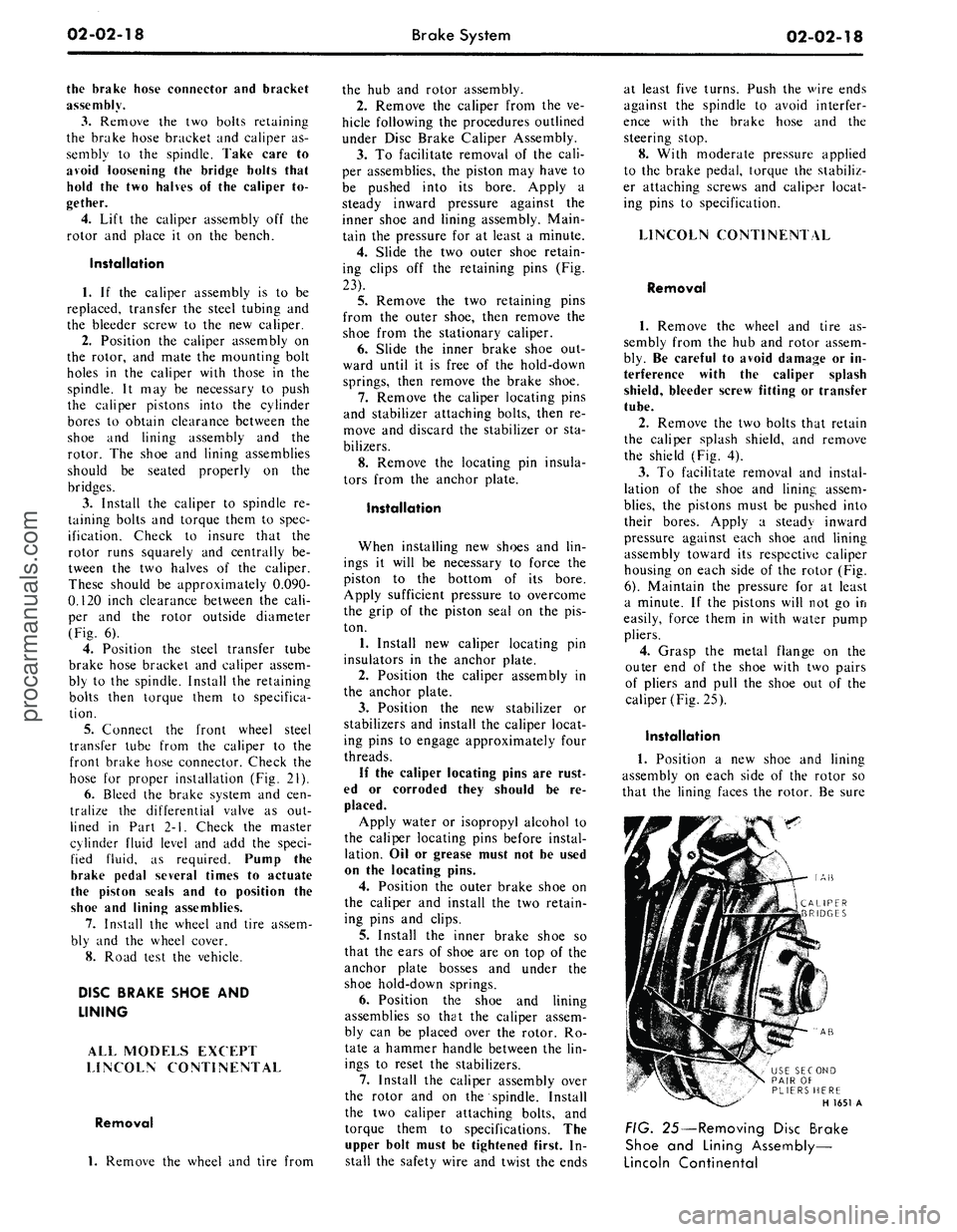
caliper (Fig.
25).
Installation
1.
Position
a new
shoe
and
lining
assembly
on
each side
of the
rotor
so
that
the
lining faces
the
rotor.
Be
sure
AB
AB
USE SECOND
PAIR
OF
PLIERS HERE
H 1651
A
FIG. 25—Removing Disc Brake
Shoe
and
Lining Assembly—
Lincoln Continentalprocarmanuals.com
Page 224 of 413
04-03-04
Rear Axles — Integral Carrier Type
04-03-04
1.
Remove the wheel cover, wheel
and tire from the brake drum.
2.
Remove the Tinnerman nuts that
secure the brake drum to the axle
housing flange, and then remove the
drum from the flange.
3.
Working through the hole pro-
vided in each axle shaft flange, re-
move the nuts that secure the wheel
bearing retainer plate. Then pull the
axle shaft assembly out of the axle
housing (Fig. 2). The brake backing
plate must, not be dislodged. Install
one nut to hold the plate in place after
the axle shaft is removed.
4.
If the rear wheel bearing is to be
replaced, loosen the inner retainer
ring by nicking it deeply with a cold
chisel in several places (Fig. 3). It will
then slide off easily.
5.
Remove the bearing from the
axle shaft with the tool shown in Fig.
4 or 5. If the push-puller operation
shown in Fig. 5 is used, be sure that
the puller arms contact the flat sur-
face of the axle shaft flange rather
than the bolt heads. Also with this
method, be careful not to damage or
burr the oil seal journal as the bearing
breaks loose.
6. Whenever a rear axle shaft is re-
placed the oil seal must be replaced.
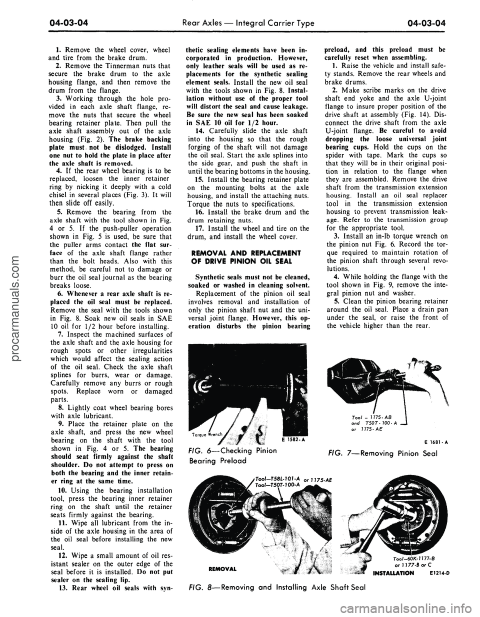
Remove the seal with the tools shown
in Fig. 8. Soak new oil seals in SAE
10 oil for 1/2 hour before installing.
7.
Inspect the machined surfaces of
the axle shaft and the axle housing for
rough spots or other irregularities
which would affect the sealing action
of the oil seal. Check the axle shaft
splines for burrs, wear or damage.
Carefully remove any burrs or rough
spots.
Replace worn or damaged
parts.
8. Lightly coat wheel bearing bores
with axle lubricant.
9. Place the retainer plate on the
axle shaft, and press the new wheel
bearing on the shaft with the tool
shown in Fig. 4 or 5. The bearing
should seat firmly against the shaft
shoulder. Do not attempt to press on
both the bearing and the inner retain-
er ring at the same time.
10.
Using the bearing installation
tool, press the bearing inner retainer
ring on the shaft until the retainer
seats firmly against the bearing.
11.
Wipe all lubricant from the in-
side of the axle housing in the area of
the oil seal before installing the new
seal.
12.
Wipe a small amount of oil res-
istant sealer on the outer edge of the
seal before it is installed. Do not put
sealer on the sealing lip.
13.
Rear wheel oil seals with syn-
thetic sealing elements have been in-
corporated in production. However,
only leather seals will be used as re-
placements for the synthetic sealing
element seals. Install the new oil seal
with the tools shown in Fig. 8. Instal-
lation without use of the proper tool
will distort the seal and cause leakage.
Be sure the new seal has been soaked
in SAE 10 oil for 1/2 hour.
14.
Carefully slide the axle shaft
into the housing so that the rough
forging of the shaft will not damage
the oil seal. Start the axle splines into
the side gear, and push the shaft in
until the bearing bottoms in the housing.
15.
Install the bearing retainer plate
on the mounting bolts at the axle
housing, and install the attaching nuts.
Torque the nuts to specifications.
16.
Install the brake drum and the
drum retaining nuts.
17.
Install the wheel and tire on the
drum, and install the wheel cover.
REMOVAL AND REPLACEMENT
OF DRIVE PINION OIL SEAL
Synthetic seals must not be cleaned,
soaked or washed in cleaning solvent.
Replacement of the pinion oil seal
involves removal and installation of
only the pinion shaft nut and the uni-
versal joint flange. However, this op-
eration disturbs the pinion bearing
preload, and this preload must be
carefully reset when assembling.
1.
Raise the vehicle and install safe-
ty stands. Remove the rear wheels and
brake drums.
2.
Make scribe marks on the drive
shaft end yoke and the axle U-joint
flange to insure proper position of the
drive shaft at assembly (Fig. 14). Dis-
connect the drive shaft from the axle
U-joint flange. Be careful to avoid
dropping the loose universal joint
bearing cups. Hold the cups on the
spider with tape. Mark the cups so
that they will be in their original posi-
tion in relation to the flange when
they are assembled. Remove the drive
shaft from the transmission extension
housing. Install an oil seal replacer
tool in the transmission extension
housing to prevent transmission leak-
age.
Refer to the transmission group
for the appropriate tool.
3.
Install an in-lb torque wrench on
the pinion nut Fig. 6. Record the tor-
que required to maintain rotation of
the pinion shaft through several revo-
lutions. \
4.
While holding the flange with the
tool shown in Fig. 9, remove the inte-
gral pinion nut and washer.
5.
Clean the pinion bearing retainer
around the oil seal. Place a drain pan
under the seal, or raise the front of
the vehicle higher than the rear.
KJ
E
I582-A
Tool - 1175-AB
and T50T-100-A
^___ or
J
775-
AE
Torque Wrench
^ mm i e
icot
A
E 1681-A
FIG. 6—Checking Pinion FiG 7_Removing
pjnjon
Sea,
Bearing Preload
,Tool-T58L-101-A or U75-AE
Tool-T50T-100-A
REMOVAL
Tool-60K-1177-B
or 1177-BorC
INSTALLATION E1214-D
FIG. 8—Removing and Installing Axle Shaft Sealprocarmanuals.com
Page 300 of 413
07-01-09
General Transmission Service
07-01-09
For example, on a C4 transmission,
if the pressure at 10 inches of vacuum
was 120 psi and the pressure at 1.0
inch of vacuum was 170 psi, and up-
shifts and downshifts were harsh, a di-
aphragm adjustment to reduce the di-
aphragm assembly spring force would
be required.
If the pressure readings are low, an
adjustment to increase diaphragm
spring force is required.
To increase control pressure, turn
the adjusting screw in clockwise to re-
duce control pressure, back the adjust-
ing screw out by turning it counte-
rclockwise. One complete turn of the
adjusting screw (360 degrees) will
change idle line control pressure ap-
proximately 2-3 psi. After the adjust-
ment is made, install the vacuum line
and make all the pressure checks as
outlined in the Specification Section.
The diaphragm should not be ad-
justed to provide pressure below the
ranges shown in the Specification Sec-
tion in order to change shift feel. To
do so could result in soft or slipping
shift points and damage to the trans-
mission.
ALTITUDE
COMPENSATING TYPE
The altitude—compensating di-
aphragm is provided with an adjust-
ment screw located in the vacuum
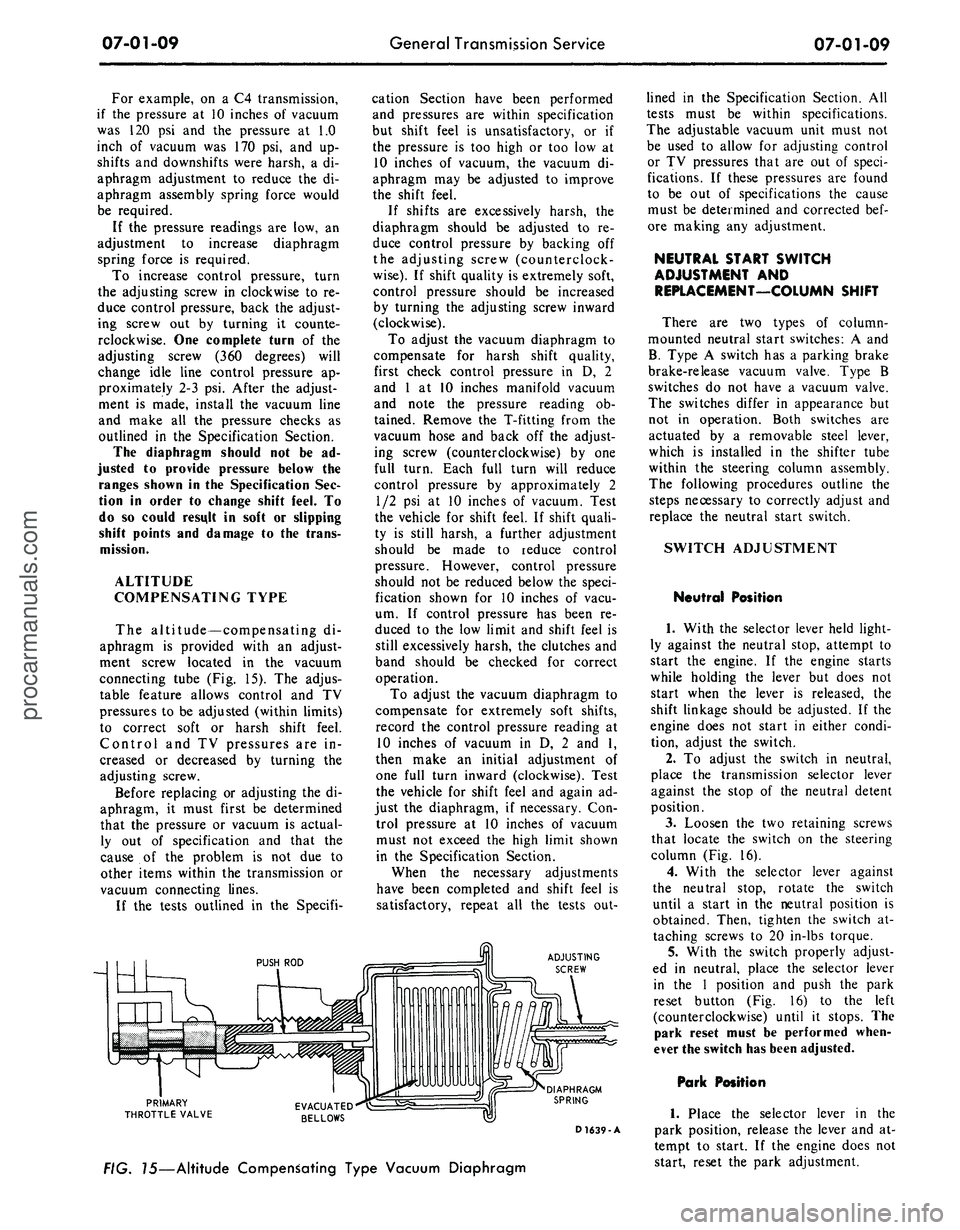
connecting tube (Fig. 15). The adjus-
table feature allows control and TV
pressures to be adjusted (within limits)
to correct soft or harsh shift feel.
Control and TV pressures are in-
creased or decreased by turning the
adjusting screw.
Before replacing or adjusting the di-
aphragm, it must first be determined
that the pressure or vacuum is actual-
ly out of specification and that the
cause of the problem is not due to
other items within the transmission or
vacuum connecting lines.
If the tests outlined in the Specifi-
cation Section have been performed
and pressures are within specification
but shift feel is unsatisfactory, or if
the pressure is too high or too low at
10 inches of vacuum, the vacuum di-
aphragm may be adjusted to improve
the shift feel.
If shifts are excessively harsh, the
diaphragm should be adjusted to re-
duce control pressure by backing off
the adjusting screw (counterclock-
wise).
If shift quality is extremely soft,
control pressure should be increased
by turning the adjusting screw inward
(clockwise).
To adjust the vacuum diaphragm to
compensate for harsh shift quality,
first check control pressure in D, 2
and 1 at 10 inches manifold vacuum
and note the pressure reading ob-
tained. Remove the T-fitting from the
vacuum hose and back off the adjust-
ing screw (counterclockwise) by one
full turn. Each full turn will reduce
control pressure by approximately 2
1/2 psi at 10 inches of vacuum. Test
the vehicle for shift feel. If shift quali-
ty is still harsh, a further adjustment
should be made to reduce control
pressure. However, control pressure
should not be reduced below the speci-
fication shown for 10 inches of vacu-
um. If control pressure has been re-
duced to the low limit and shift feel is
still excessively harsh, the clutches and
band should be checked for correct
operation.
To adjust the vacuum diaphragm to
compensate for extremely soft shifts,
record the control pressure reading at
10 inches of vacuum in D, 2 and 1,
then make an initial adjustment of
one full turn inward (clockwise). Test
the vehicle for shift feel and again ad-
just the diaphragm, if necessary. Con-
trol pressure at 10 inches of vacuum
must not exceed the high limit shown
in the Specification Section.
When the necessary adjustments
have been completed and shift feel is
satisfactory, repeat all the tests out-
ADJUSTING
SCREW
PRIMARY
THROTTLE VALVE
DIAPHRAGM
SPRING
D 1639-A
FIG. 15—Altitude Compensating Type Vacuum Diaphragm
lined in the Specification Section. All
tests must be within specifications.
The adjustable vacuum unit must not
be used to allow for adjusting control
or TV pressures that are out of speci-
fications. If these pressures are found
to be out of specifications the cause
must be determined and corrected bef-
ore making any adjustment.
NEUTRAL START SWITCH
ADJUSTMENT AND
REPLACEMENT—COLUMN SHIFT
There are two types of column-
mounted neutral start switches: A and
B.
Type A switch has a parking brake
brake-release vacuum valve. Type B
switches do not have a vacuum valve.
The switches differ in appearance but
not in operation. Both switches are
actuated by a removable steel lever,
which is installed in the shifter tube
within the steering column assembly.
The following procedures outline the
steps necessary to correctly adjust and
replace the neutral start switch.
SWITCH ADJUSTMENT
Neutral Position
1.
With the selector lever held light-
ly against the neutral stop, attempt to
start the engine. If the engine starts
while holding the lever but does not
start when the lever is released, the
shift linkage should be adjusted. If the
engine does not start in either condi-
tion, adjust the switch.
2.
To adjust the switch in neutral,
place the transmission selector lever
against the stop of the neutral detent
position.
3.
Loosen the two retaining screws
that locate the switch on the steering
column (Fig. 16).
4.
With the selector lever against
the neutral stop, rotate the switch
until a start in the neutral position is
obtained. Then, tighten the switch at-
taching screws to 20 in-lbs torque.
5.
With the switch properly adjust-
ed in neutral, place the selector lever
in the 1 position and push the park
reset button (Fig. 16) to the left
(counterclockwise) until it stops. The
park reset must be performed when-
ever the switch has been adjusted.
Park Position
1.
Place the selector lever in the
park position, release the lever and at-
tempt to start. If the engine does not
start, reset the park adjustment.procarmanuals.com
Page 301 of 413
07-01-10
General Transmission Service
07-01-10
2.
To adjust the switch for the park
position, place the transmission selec-
tor lever in 1 and push the park reset
button (Fig. 16) to the left (counter-
clockwise) until it stops.
3.
Check the operation of the
switch in each selector lever position.
The starter should engage in only the
neutral and park positions. Be sure to
perform
the
park reset
if for any rea-
son
the
neutral switch
is
adjusted.
If,
after performing
the
switch
ad-
justments,
the
starter still will
not en-
gage
in the
neutral
or
park positions,
replace
the
switch. Never replace
the
neutral switch until
the
switch adjust-
ments have been made.
SWITCH REPLACEMENT
1.
Disconnect the neutral start
switch wires at the plug connector.
2.
Disconnect the vacuum hoses, if
so equipped.
3.
Remove the two screws securing
the neutral start switch to the steering
column and lift the switch from the
column.
Check the column to be sure the
metal switch actuator is secure to the
shift tube and that it is seated as far
forward against the shift tube bearing
as is possible. Also check for a broken
or damaged actuator. If it is broken
or damaged, replace it as shown in
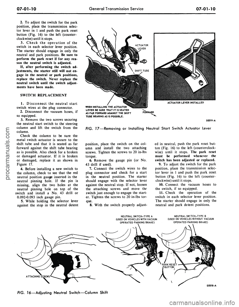
Figure 17.
4.
Before installing a new switch to
the column, check to see that the red
neutral position gauge inserted in the
neutral pinning hole. If the pin is
missing, align the two holes at the
neutral pinning hole on top of the
switch and install a No. 43 drill or
0.092-0.093 inch gauge pin.
5.
While holding the selector lever
against the stop in the neutral detent
ACTUATOR LEVER INSTALLED
WHEN INSTALLING
THE
ACTUATOR
LEVER
BE
SURE THAT
IT
1$ SEATED
AS
FAR
FORWARD AGAINST
THE
SHIFT
TUBE BEARING
AS IS
POSSIBLE.
FORWARD
D2019-A
FIG. 17—Removing
or
Installing Neutral Start Switch Actuator Lever
position, place the switch on the col-
umn and install the two attaching
screws. Tighten the screws to 20 in-lbs
torque.
6. Remove the gauge pin (or No.
43 drill if used).
7.
Connect the switch wires to the
plug connector and check for a start
in the neutral position. The starter
should engage with the selector lever
against the neutral stop. If not, loosen
the attaching screws and move the
switch just enough to engage the start-
er. Tighten the screws to 20 in-lbs tor-
que.
8. With the switch properly adjust-
ed in neutral, push the park reset but-
ton (Fig. 16) to the left (counterclock-
wise) until it stops. The park reset
must be performed whenever the
switch has been adjusted or replaced.
9. To adjust the switch for the park
position, place the transmission selec-
tor lever in 1 and push the park reset
button (Fig. 16) to the left (counter-
clockwise) until it stops.
10.
Connect the vacuum hoses to
the switch, if so equipped.
11.
Check the operation of the
switch in each selector lever position.
The starter should engage in only the
neutral and park detent positions.
NEUTRAL SWITCH-TYPE
A
(USED
ON
VEHICLES WITH VACUUM
OPFRATED PARKING BRAKE)
NEUTRAL SWITCH-TYPIE
B
(USED
ON
VEHICLES WITHOUT VACUUM
OPERATED PARKING BRAKE)
ATTACHING
FIG.
16—Ad
justing Neutral Switch—Column Shift
D2018-Aprocarmanuals.com
Page 403 of 413
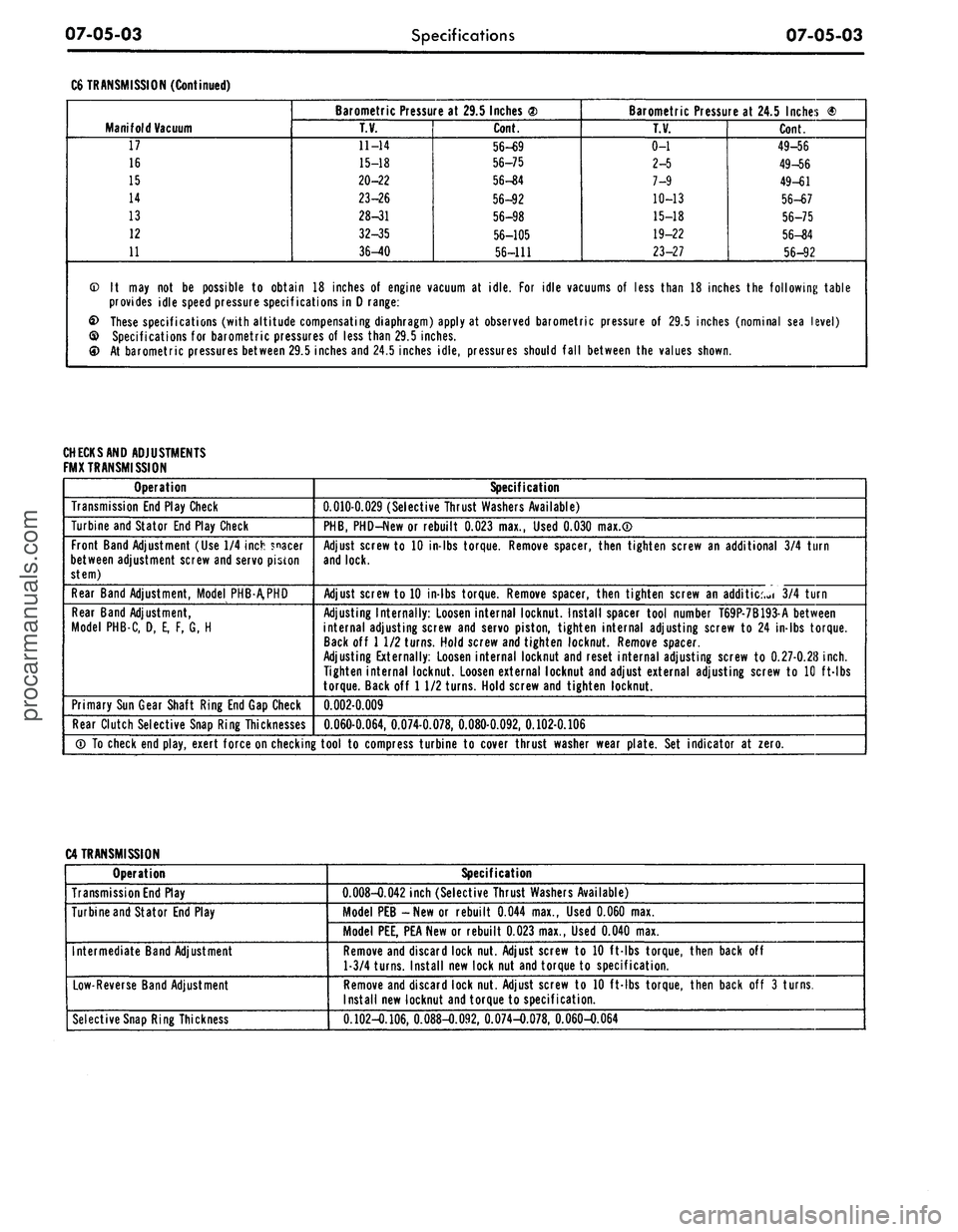
07-05-03
Specifications
07-05-03
C6 TRANSMISSION (Continued)
Manifold Vacuum
17
16
15
14
13
12
11
Barometric Pressure at 29.5 Inches <2)
T.V.
11-14
15-18
20-22
23-26
28-31
32-35
36-40
Cont.
56-69
56-75
56-S4
56-92
56-98
56-105
56-111
Barometric Pressure at 24.5 Inches ®
T.V.
0-1
2-5
7-9
10-13
15-18
19-22
23-27
Cont.
49-56
49-56
49-61
56-67
56-75
56-84
56-92
© It may not be possible to obtain 18 inches of engine vacuum at idle. For idle vacuums of less than 18 inches the following table
provides idle speed pressure specifications in D range:
£> These specifications (with altitude compensating diaphragm) apply at observed barometric pressure of 29.5 inches (nominal sea level)
© Specifications for barometric pressures of less than 29.5 inches.
At barometric pressures between 29.5 inches and 24.5 inches idle, pressures should fall between the values shown.
CHECK
SAND ADJUSTMENTS
FMX TRANSMISSION
Operation
Transmission End Play Check
Turbine and Stator End Play Check
Front Band Adjustment (Use 1/4 inch spacer
between adjustment screw and servo piston
stem)
Rear Band Adjustment, Model PHB-A.PHD
Rear Band Adjustment,
Model PHB-C, D, E, F, G, H
Primary Sun Gear Shaft Ring End Gap Check
Rear Clutch Selective Snap Ring Thicknesses
Specification
0.010-0.029 (Selective Thrust Washers Available)
PHB,
PHD-New or rebuilt 0.023 max., Used 0.030 max.®
Adjust screw to 10 in-lbs torque. Remove spacer, then tighten screw an additional 3/4 turn
and lock.
Adjust screw to 10 in-lbs torque. Remove spacer, then tighten screw an addition 3/4 turn
Adjusting Internally: Loosen internal locknut. Install spacer tool number T69P-7B193-A between
internal adjusting screw and servo piston, tighten internal adjusting screw to 24 in-lbs torque.
Back off 1 1/2 turns. Hold screw and tighten locknut. Remove spacer.
Adjusting Externally: Loosen internal locknut and reset internal adjusting screw to 0.27-0.28
inch.
Tighten internal locknut. Loosen external locknut and adjust external adjusting screw to 10 ft-lbs
torque. Back off 1 1/2 turns. Hold screw and tighten locknut.
0.002-0.009
0.060-0.064, 0.074-0.078, 0.080-0.092, 0.102-0.106
® To check end play, exert force on checking tool to compress turbine to cover thrust washer wear plate. Set indicator at zero.
C4 TRANSMISSION
Operation
Transmission End Play
Turbine and Stator End Play
Intermediate Band Adjustment
Low-Reverse Band Adjustment
Selective Snap Ring Thickness
Specification
0.008-0.042 inch (Selective Thrust Washers Available)
Model PEB -New or rebuilt 0.044 max., Used 0.060 max.
Model PEE, PEA New or rebuilt 0.023 max., Used 0.040 max.
Remove and discard lock nut. Adjust screw to 10 ft-lbs torque, then back off
1-3/4 turns. Install new lock nut and torque to specification.
Remove and discard lock nut. Adjust screw to 10 ft-lbs torque, then back off 3 turns.
Install new locknut and torque to specification.
0.102-0.106, 0.088-0.092, 0.074-0.078, 0.060-O.064procarmanuals.com