light FORD MUSTANG 1969 Volume One Chassis
[x] Cancel search | Manufacturer: FORD, Model Year: 1969, Model line: MUSTANG, Model: FORD MUSTANG 1969Pages: 413, PDF Size: 75.81 MB
Page 16 of 413

02-01-05
Brakes
02-01-05
1.
Disconnect the master cylinder
from the booster assembly and secure
away from the booster without discon-
necting the brake tubes.
2.
Reinstall the air filter assembly
on the booster if it was removed with
the master cylinder (Fig. 8).
3.
Install and tighten the master
cylinder retaining nuts to retain the
air filter assembly securely against the
booster body and to seal the booster
bellows against air leaks.
4.
Place the gauge against the
master cylinder mounting surface of
the air filter assembly.
5.
Adjust the push rod screw to
provide a slight tension against the
inner edge of the adjustment gauge
slot. (Approximately 5 pounds of ten-
sion against the push rod is required
to assure that the push rod is firmly
seated in the booster assembly.)
6. Remove the retaining nuts from
the booster master cylinder mounting
studs.
7.
Install the master cylinder on the
brake booster and tighten the retain-
ing nuts to the specified torque.
The push rod length verification of
the Bendix power brake booster
assemblies is accomplished as follows:
1.
Disconnect the master cylinder
from the booster assembly and secure
away from the booster without discon-
necting the brake tubes.
2.
Adjust the push rod screw to
provide a slight tension against the
inner edge of the adjustment gauge
slot. (Approximately 5 pounds of ten-
sion against the push rod is required
to assure that the push rod is firmly
seated in the booster assembly.) See
Figure 8.
3.
Install the master cylinder on the
brake booster and tighten the retain-
ing nuts to the specified torque.
Do not set up side forces on the
push rod as it may break the valve
plunger.
This is an approximate adjustment
only. To verify the adjustment, look
through the make-up (rear) port of the
master cylinder when installing the
master cylinder to the booster. The
master cylinder piston should not
move more than 0.015 inch as it con-
tacts the push rod. No movement
(exact contact) is ideal.
HYDRAULIC SYSTEM BLEEDING
AND CENTRALIZING OF THE
DIFFERENTIAL VALVE
When any part of the hydraulic sys-
tem has been disconnected for repair
or replacement, air may enter the sys-
tem and cause spongy pedal action.
Bleed the hydraulic system after it has
been properly connected, to be sure
that all air is expelled.
MANUAL BLEEDING
The Lincoln Continental hydraulic
brake system is to be bled only with
pressure bleeding equipment.
The primary and secondary (front
MANIFOLD CHECK VALVE-2365 19-25 IN. LB.
TIGHTEN RETAINING NUTS
TO SECURE AIR FILTER
AGAINST BOOSTER BODY
AND BELLOWS
ADJUST PUSH ROD SCREW TO
PROVIDE A SLIGHT TENSION
(APPROXIMATELY 5 LBS.)
AGAINST THE GAUGE
PUSH ROD GAUGE
and rear) hydraulic brake systems are
individual systems and are bled separ-
ately. Bleed the longest line first on
the individual system being serviced.
During the complete bleeding opera-
tion,
DO NOT allow the reservoir to
run dry. Keep the master cylinder res-
ervoirs filled with Ford Fluid—Extra
Heavy Duty — Part Number C6AZ-
19542-A (ESA-M6C 25-A). The extra
heavy duty brake fluid is colored blue
for identification purposes. Do not
mix low temperature brake fluids with
the specified fluid during the bleeding
operations. Never re-use brake fluid
which has been drained from the hy-
draulic systems.
1.
If the master cylinder is
equipped with a bleed screw, loosen
the bleed screw. Push the brake pedal
down slowly through its full travel.
Close the bleeder fitting and return
the pedal to the fully released posi-
tion. Repeat this operation until fluid
is free of air bubbles, then tighten the
bleeder screw. Do not use the second-
ary piston stop screw, located on the
bottom of the master cylinder to bleed
the brake system. Loosening or re-
moving this screw could result in dam-
age to the secondary piston or stop
screw.
2.
To bleed the secondary (rear)
brake system, position a suitable 3/8
inch box wrench (Fig. 9) on the bleed-
er fitting on the brake wheel cylinder.
Attach a rubber drain tube to the
bleeder fitting. The end of the tube
should fit snugly around the bleeder
fitting.
APPROXIMATELY 45°
PUSH ROD ADJUSTMENT-MIDLAND-ROSS
FIG. 8—Brake Booster Push Rod Measurement
PUSH ROD ADJUSTMENT-BENDIX
H1589-A
H1300-B
. 9—Wrench for Bleeding
Brake Hydraulic System
3.
Submerge the free end of the
tube in a container partially filled with
clean brake fluid, and loosen the
bleeder fitting approximately 3/4 turn.
4.
Push the brake pedal down slow-
ly through its full travel. Close the
bleeder fitting, then return the pedal
to the full-released position. Repeat
this operation until air bubbles cease
to appear at the submerged end of the
bleeder tube.
5.
When the fluid is completely free
of air bubbles, close the bleeder fitting
and remove the bleeder tube.
6. Repeat this procedure at the
brake wheel cylinder on the oppositeprocarmanuals.com
Page 18 of 413
02-01-07
Brakes
02-01-07
CENTRALIZING THE
PRESSURE DIFFERENTIAL
VALVE
After a failure of the primary (front
brake) or secondary (rear brake) sys-
tem has been repaired and bled, the
dual-brake warning light will usually
continue to be illuminated due to the
pressure differential valve remaining in
the off-center position.
To centralize the pressure differen-
tial valve and turn off the warning
light after a repair operation, a pres-
sure differential or unbalance condi-
tion must be created in the opposite
brake system from the one that was
repaired or bled last.
1.
Turn the ignition switch to the
ACC or ON position. Loosen the dif-
ferential valve assembly brake tube
nut at the outlet port on the opposite
side of the brake system that was
wheel balanced, repaired and/or bled
last. Depress the brake pedal slowly to
build line pressure until the pressure
differential valve is moved to a cen-
tralized position and the brake warn-
ing light goes out; then, immediately
tighten the outlet port tube nut.
2.
Check the fluid level in the mas-
ter cylinder reservoirs and fill them to
within 1/4 inch of the top with the
specified brake fluid, if necessary.
3.
Turn the ignition switch to the
OFF position.
4.
Before driving the vehicle, check
the operation of the brakes and be
sure that a firm pedal is obtained.
CLEANING AND INSPECTION
DISC BRAKES
1.
Remove the wheel and tire and
the shoe and lining assemblies as out-
lined in Part 2-2, Section 2.
2.
On all models except Lincoln
Continental, make thickness measure-
ments with a micrometer across the
thinnest section of the shoe and lining.
If the assembly has worn to a thick-
ness of 0.230-inch (shoe and lining to-
gether) or 0.030-inch (lining material
only) at any one of three measuring
locations or if there is more than
0.125 taper from end to end or if lin-
ing shows evidence of brake fluid con-
tamination, replace all (4) shoe and
lining assemblies on both front wheels.
On Lincoln Continental brakes
make three thickness measurements
with a micrometer across the middle
section of the shoe and lining. Take
one reading at each side and one in
the center. If the assembly has worn
to a thickness of 0.231 inch (shoe and
lining together) or 0.066 inch (lining
material only) at any one of the three
measuring locations, replace all (4)
shoe and lining assemblies on both
front wheels.
3.
Check the caliper to spindle at-
taching bolts torque. Torque them to
specification, if required.
4.
To check rotor runout, first
eliminate the wheel bearing end play
by tightening the adjusting nut. After
tightening the nut, check to see that
the rotor can still be rotated.
5.
Clamp a dial indicator to the
caliper housing so that the stylus con-
tact the rotor at a point approximate-
ly 1 inch from the outer edge. Rotate
the rotor and take an indicator read-
ing. If the reading exceeds 0.003 inch
total lateral runout on the indicator,
replace or resurface the disc brake
rotor. The following requirement must
be met when resurfacing disc brake
rotors:
Rotunda Disc Brake Attachment
FRE-2249-2 is the only approved tool
to be used to refinish the disc brake
rotors.
The step-by-step resurfacing
procedure provided with the tool must
be adhered to.
The finished braking surface of the
rotor must be flat and parallel within
0.0007 inch; lateral runout must not
exceed 0.003 inch total indicator
reading, braking surface are to be 80/15
micro inches.
On all models except Lincoln Con-
tinental the minimum limiting dimen-
sion from the inboard bearing cup to
the inboard rotor face and the mini-
mum rotor thickness dimension, must
be observed when removing material
from the rotor braking surfaces. A
ball and gage bar (Rotunda Kit FRE
70160) is to be used when checking
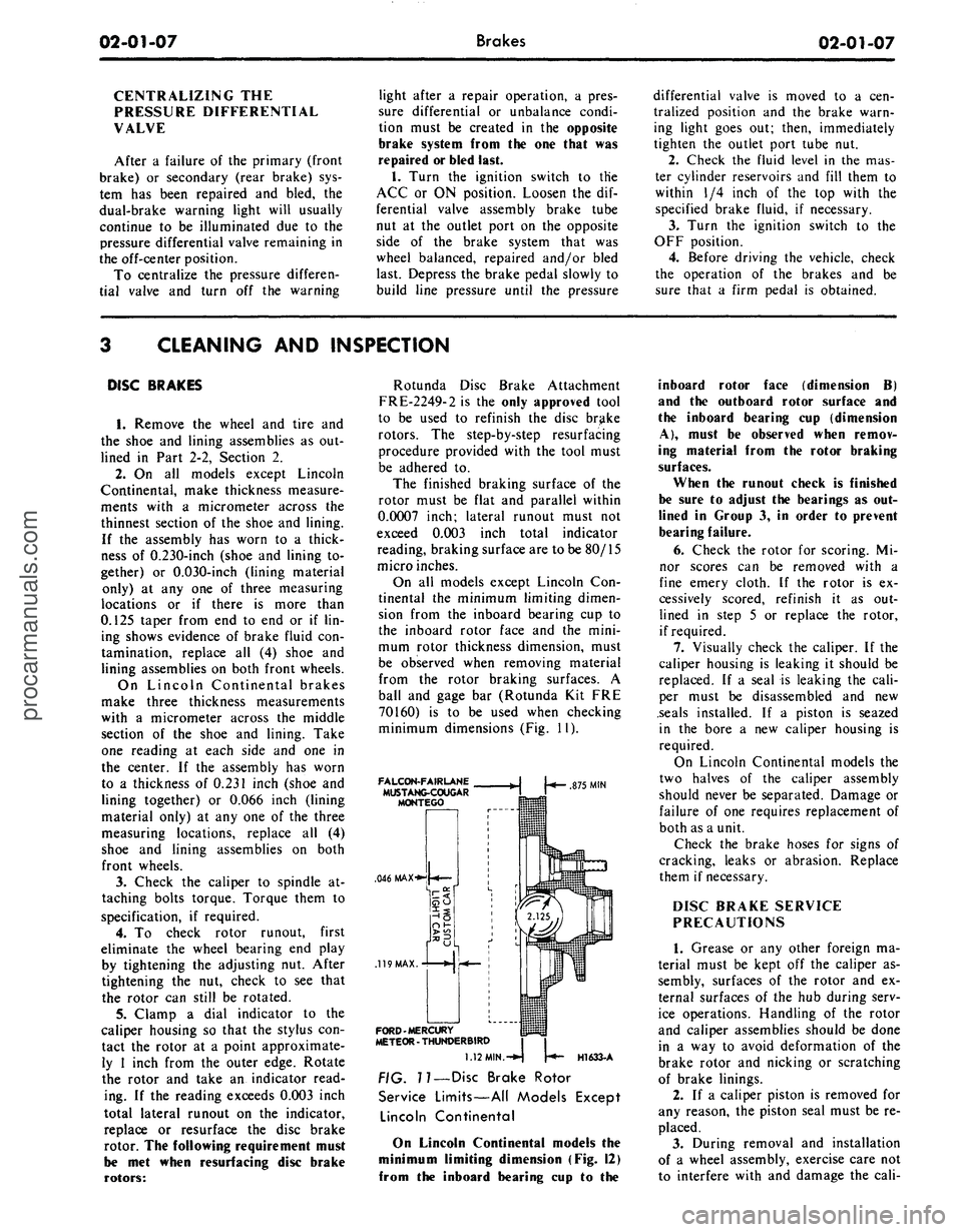
minimum dimensions (Fig. 11).
FALCON-FAIRLANE
MUSTANG-COUGAR
MONTEGO
.046 MAX-**
.119
MAX.
FORD-MERCURY
METEOR - THUNDERBIRD
875
MIN
H1633-A
1.12
MIN.-^
??
— Disc Brake Rotor
Service Limits—All Models Except
Lincoln Continental
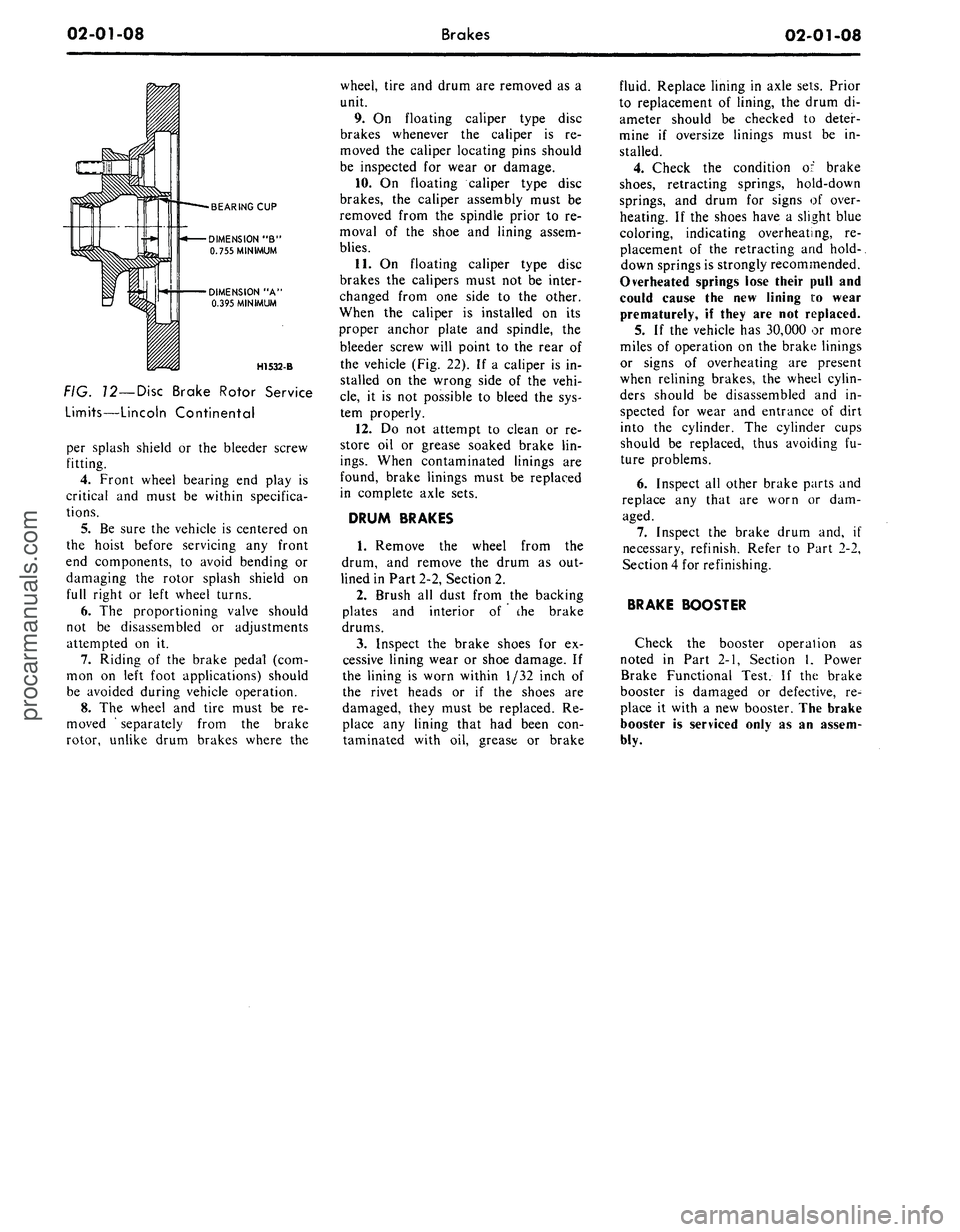
On Lincoln Continental models the
minimum limiting dimension (Fig. 12)
from the inboard bearing cup to the
inboard rotor face (dimension B)
and the outboard rotor surface and
the inboard bearing cup (dimension
A),
must be observed when remov-
ing material from the rotor braking
surfaces.
When the runout check is finished
be sure to adjust the bearings as out-
lined in Group 3, in order to prevent
bearing failure.
6. Check the rotor for scoring. Mi-
nor scores can be removed with a
fine emery cloth. If the rotor is ex-
cessively scored, refinish it as out-
lined in step 5 or replace the rotor,
if required.
7.
Visually check the caliper. If the
caliper housing is leaking it should be
replaced. If a seal is leaking the cali-
per must be disassembled and new
.seals installed. If a piston is seazed
in the bore a new caliper housing is
required.
On Lincoln Continental models the
two halves of the caliper assembly
should never be separated. Damage or
failure of one requires replacement of
both as a unit.
Check the brake hoses for signs of
cracking, leaks or abrasion. Replace
them if necessary.
DISC BRAKE SERVICE
PRECAUTIONS
1.
Grease or any other foreign ma-
terial must be kept off the caliper as-
sembly, surfaces of the rotor and ex-
ternal surfaces of the hub during serv-
ice operations. Handling of the rotor
and caliper assemblies should be done
in a way to avoid deformation of the
brake rotor and nicking or scratching
of brake linings.
2.
If a caliper piston is removed for
any reason, the piston seal must be re-
placed.
3.
During removal and installation
of a wheel assembly, exercise care not
to interfere with and damage the cali-procarmanuals.com
Page 19 of 413
02-01-08
Brakes
02-01-08
BEARING CUP
DIMENSION "B"
0.755 MINIMUM
DIMENSION "A'
0.395 MINIMUM
H1532-B
FIG. 12—Disc Brake Rotor Service
Limits—Lincoln Continental
per splash shield or the bleeder screw
fitting.
4.
Front wheel bearing end play is
critical and must be within specifica-
tions.
5.
Be sure the vehicle is centered on
the hoist before servicing any front
end components, to avoid bending or
damaging the rotor splash shield on
full right or left wheel turns.
6. The proportioning valve should
not be disassembled or adjustments
attempted on it.
7.
Riding of the brake pedal (com-
mon on left foot applications) should
be avoided during vehicle operation.
8. The wheel and tire must be re-
moved ' separately from the brake
rotor, unlike drum brakes where the
wheel, tire and drum are removed as a
unit.
9. On floating caliper type disc
brakes whenever the caliper is re-
moved the caliper locating pins should
be inspected for wear or damage.
10.
On floating caliper type disc
brakes, the caliper assembly must be
removed from the spindle prior to re-
moval of the shoe and lining assem-
blies.
11.
On floating caliper type disc
brakes the calipers must not be inter-
changed from one side to the other.
When the caliper is installed on its
proper anchor plate and spindle, the
bleeder screw will point to the rear of
the vehicle (Fig. 22). If a caliper is in-
stalled on the wrong side of the vehi-
cle,
it is not possible to bleed the sys-
tem properly.
12.
Do not attempt to clean or re-
store oil or grease soaked brake lin-
ings.
When contaminated linings are
found, brake linings must be replaced
in complete axle sets.
DRUM BRAKES
1.
Remove the wheel from the
drum, and remove the drum as out-
lined in Part 2-2, Section 2.
2.
Brush all dust from the backing
plates and interior of the brake
drums.
3.
Inspect the brake shoes for ex-
cessive lining wear or shoe damage. If
the lining is worn within 1/32 inch of
the rivet heads or if the shoes are
damaged, they must be replaced. Re-
place any lining that had been con-
taminated with oil, grease or brake
fluid. Replace lining in axle sets. Prior
to replacement of lining, the drum di-
ameter should be checked to deter-
mine if oversize linings must be in-
stalled.
4.
Check the condition of brake
shoes,
retracting springs, hold-down
springs, and drum for signs of over-
heating. If the shoes have a slight blue
coloring, indicating overheating, re-
placement of the retracting and hold-.
down springs is strongly recommended.
Overheated springs lose their pull and
could cause the new lining i:o wear
prematurely, if they are not replaced.
5. If the vehicle has 30,000 or more
miles of operation on the brake linings
or signs of overheating are present
when relining brakes, the wheel cylin-
ders should be disassembled and in-
spected for wear and entrance of dirt
into the cylinder. The cylinder cups
should be replaced, thus avoiding fu-
ture problems.
6. Inspect all other brake parts and
replace any that are worn or dam-
aged.
7.
Inspect the brake drum and, if
necessary, refinish. Refer to Part 2-2,
Section 4 for refinishing.
BRAKE BOOSTER
Check the booster operation as
noted in Part 2-1, Section 1, Power
Brake Functional Test. If the brake
booster is damaged or defective, re-
place it with a new booster. The brake
booster is serviced only as an assem-
bly.procarmanuals.com
Page 22 of 413
02-02-03
Brake System
02-02-03
DESCRIPTION
Disc brakes are available as option-
al equipment for the front wheels on
Ford, Mercury, Meteor, Fairlane,
Montego, Falcon, Mustang and Cou-
gar models and are standard on Thun-
derbird, Continental Mark III, and
Lincoln Continental models. The
dual-master cylinder equipped hydrau-
lic brake system employs single an-
chor, internal expanding and
self-
adjusting drum brake assemblies on
the rear wheels of vehicles with disc
brakes, and on the front and rear
wheels of all others.
A vacuum booster is used with the
power disc brake system.
DUAL MASTER CYLINDER
BRAKE SYSTEM
The dual-master cylinder brake sys-
tem has been incorporated in all mod-
els to provide increased safety. The
system consists of a dual-master cylin-
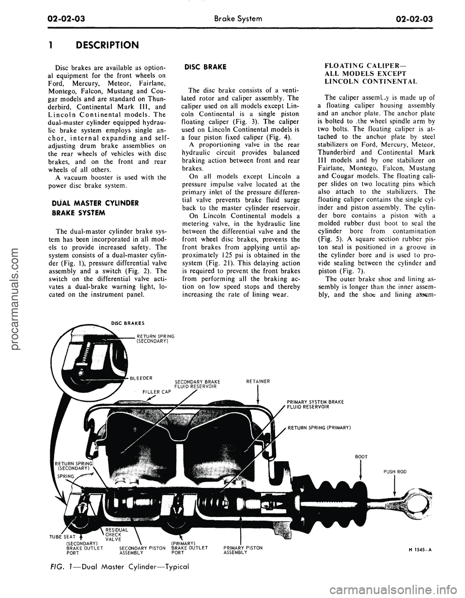
der (Fig. 1), pressure differential valve
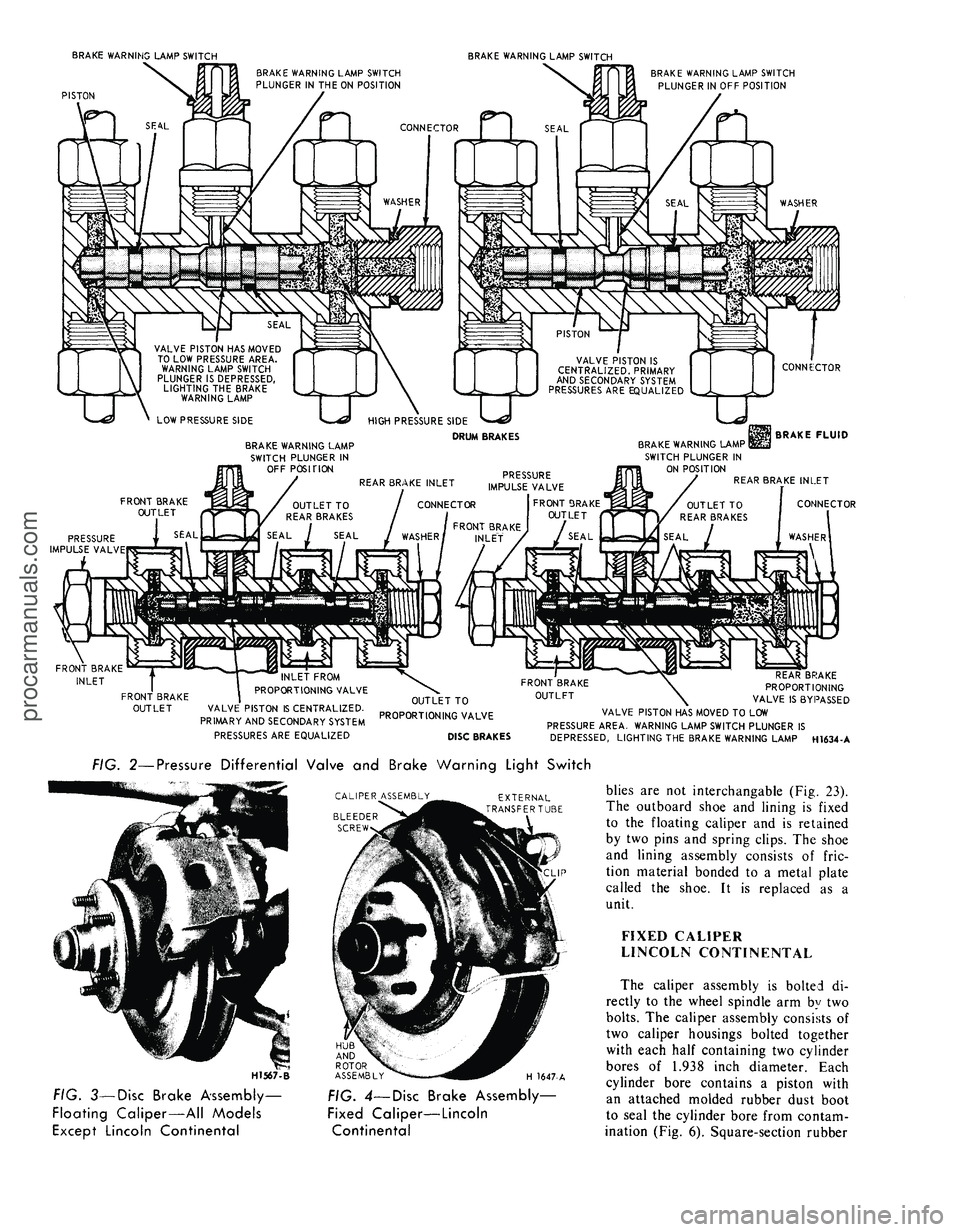
assembly and a switch (Fig. 2). The
switch on the differential valve acti-
vates a dual-brake warning light, lo-
cated on the instrument panel.
DISC BRAKE
The disc brake consists of a venti-
lated rotor and caliper assembly. The
caliper used on all models except Lin-
coln Continental is a single piston
floating caliper (Fig. 3). The caliper
used on Lincoln Continental models is
a four piston fixed caliper (Fig. 4).
A proportioning valve in the rear
hydraulic circuit provides balanced
braking action between front and rear
brakes.
On all models except Lincoln a
pressure impulse valve located at the
primary inlet of the pressure differen-
tial valve prevents brake fluid surge
back to the master cylinder reservoir.
On Lincoln Continental models a
metering valve, in the hydraulic line
between the differential valve and the
front wheel disc brakes, prevents the
front brakes from applying until ap-
proximately 125 psi is obtained in the
system (Fig. 21). This delaying action
is required to prevent the front brakes
from performing all the braking ac-
tion on low speed stops and thereby
increasing the rate of lining wear.
FLOATING CALIPER—
ALL MODELS EXCEPT
LINCOLN CONTINENTAL
The caliper asseml.y is made up of
a floating caliper housing assembly
and an anchor plate. The anchor plate
is bolted to .the wheel spindle arm by
two bolts. The floating caliper is at-
tached to the anchor plate by steel
stabilizers on Ford, Mercury, Meteor,
Thunderbird and Continental Mark
III models and by one stabilizer on
Fairlane, Montego, Falcon, Mustang
and Cougar models. The floating cali-
per slides on two locating pins which
also attach to the stabilizers. The
floating caliper contains the single cyl-
inder and piston assembly. The cylin-
der bore contains a piston with a
molded rubber dust boot to seal the
cylinder bore from contamination
(Fig. 5). A square section rubber pis-
ton seal is positioned in a groove in
the cylinder bore and is used to pro-
vide sealing between the cylinder and
piston (Fig. 7).
The outer brake shoe and lining as-
sembly is longer than the inner assem-
bly, and the shoe and lining
DISC BRAKES
RETURN SPRING
(SECONDARY)
RETAINER
PRIMARY SYSTEM BRAKE
FLUID RESERVOIR
BOOT
PUSH ROD
TUBE SEAT |
(SECONDARY)
BRAKE OUTLET
PORT
RESIDUAL \ ^
CHECK \
VALVE \
SECONDARY PISTON
ASSEMBLY
(PRIMARY)
BRAKE OUTLET
PORT
PRIMARY PISTON
ASSEMBLY
H 1545-A
FIG.
I
—
Dual
Master Cylinder—Typicalprocarmanuals.com
Page 23 of 413
BRAKE WARNING LAMP SWITCH
PISTON
BRAKE WARNING LAMP SWITCH
BRAKE WARNING LAMP SWITCH
PLUNGER IN THE ON POSITION
CONNECTOR
BRAKE WARNING LAMP SWITCH
PLUNGER IN OFF POSITION
VALVE PISTON HAS MOVED
TO LOW PRESSURE AREA.
WARNING LAMP SWITCH
PLUNGER IS DEPRESSED,
LIGHTING THE BRAKE
WARNING LAMP
LOW PRESSURE SIDE
U
VALVE PISTON IS
CENTRALIZED. PRIMARY
AND SECONDARY SYSTEM
PRESSURES ARE EQUALIZED
BRAKE WARNING LAMP
SWITCH PLUNGER IN
OFF POSITION
HIGH PRESSURE SIDE
DRUM BRAKES
TJ
CONNEiCTOR
BRAKE FLUID
BRAKE WARNING LAMP I
SWITCH PLUNGER IN
ON POSITION
REAR BRAKE INLET
CONNECTOR
FRONT BRAKE
INLET
FRONT BRAKE
OUTLET
VALVE PISTON IS CENTRALIZED.
PRIMARY AND SECONDARY SYSTEM
PRESSURES ARE EQUALIZED
OUTLET TO
PROPORTIONING VALVE
DISC BRAKES
\
REAR BRAKE
PROPORTIONING
VALVE IS BYPASSED
VALVE PISTON HAS MOVED TO LOW
PRESSURE AREA. WARNING LAMP SWITCH PLUNGER IS
DEPRESSED, LIGHTING THE BRAKE WARNING LAMP H1634-A
FIG. 2—Pressure Differential Valve and Brake Warning Light Switch
CALIPER ASSEMBLY
BLEEDER
SCREW
EXTERNAL
TRANSFERTU3E
H1567-B
HUB
AND
ROTOR
ASSEMBLY
H 1647-A
FIG. 3—Disc Brake Assembly-
Floating Caliper—All Models
Except Lincoln Continental
FIG. 4—Disc Brake Assembly—
Fixed Caliper—Lincoln
Continental
blies are not interchangable (Fig. 23).
The outboard shoe and lining is fixed
to the floating caliper and is retained
by two pins and spring clips. The shoe
and lining assembly consists of fric-
tion material bonded to a metal plate
called the shoe. It is replaced as a
unit.
FIXED CALIPER
LINCOLN CONTINENTAL
The caliper assembly is bolted di-
rectly to the wheel spindle arm by two
bolts.
The caliper assembly consists of
two caliper housings bolted together
with each half containing two cylinder
bores of 1.938 inch diameter. Each
cylinder bore contains a piston with
an attached molded rubber dust boot
to seal the cylinder bore from contam-
ination (Fig. 6). Square-section rubberprocarmanuals.com
Page 27 of 413
02-02-08
Brake System
02-02-08
Tool-HRE-8650
JUST SET TO DRUM
DIAMETER HERE . . .
FIND CORRECT BRAKE
SHOE DIAMETER HERE
H1416-A
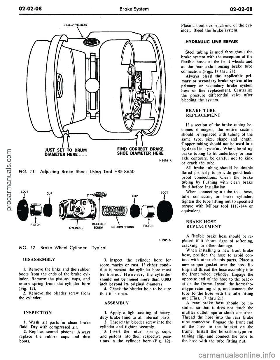
FIG.
7
7—Adjusting Brake Shoes Using Tool HRE-8650
BOOT
BOOT
PISTON
. BLEEDER .
CYLINDER
SCREW RETURN SPRING PIST0N
H1385-B
FIG. 72—Brake Wheel Cylinder—Typical
DISASSEMBLY
1.
Remove the links and the rubber
boots from the ends of the brake cyl-
inder. Remove the pistons, cups, and
return spring from the cylinder bore
(Fig. 12).
2.
Remove the bleeder screw from
the cylinder.
INSPECTION
1.
Wash all parts in clean brake
fluid. Dry with compressed air.
2.
Replace scored pistons. Always
replace the rubber cups and dust
boots.
3.
Inspect the cylinder bore for
score marks or rust. If either condi-
tion is present the cylinder bore must
be honed. However, the cylinder
should not be honed more than 0.003
inch beyond its original diameter.
4.
Check the bleeder hole to be sure
that it is open.
ASSEMBLY
1.
Apply a light coating of heavy-
duty brake fluip! to all internal parts.
2.
Thread the bleeder screw into the
cylinder and tighten securely.
3.
Insert the return spring, cups,
and pistons into their respective posi-
tions in the cylinder bore (Fig. 12).
Place a boot over each end of the cyl-
inder. Bleed the brake system.
HYDRAULIC LINE REPAIR
Steel tubing is used throughout the
brake system with the exception of the
flexible hoses at the front wheels and
at the fear axle housing brake tube
connection (Figs. 17 thru 21).
Always bleed the applicable pri-
mary or secondary brake system after
primary or secondary brake system
hose or line replacement. Centralize
the pressure differential valve after
bleeding the system.
BRAKE TUBE
REPLACEMENT
If a section of the brake tubing be-
comes damaged, the entire section
should be replaced with tubing of the
same type, size, shape and length.
Copper tubing should not be used in a
hydraulic system. When bending
brake tubing to fit underbody or rear
axle contours, be careful not to kink
or crack the tube.
All brake tubing should be double
flared properly to provide good leak-
proof connections. Clean the brake
tubing by flushing with clean brake
fluid before installation.
When connecting a tube to a hose,
tube connector, or brake cylinder,
tighten the tube fitting nut to specified
torque with Milbar tool 1112-144 or
equivalent.
BRAKE HOSE
REPLACEMENT
A flexible brake hose should be re-
placed if it shows signs of softening,
cracking, or other damage.
When installing a new front brake
hose,
position the hose to avoid con-
tact with other chassis parts. Place a
new copper gasket over the hose fit-
ting and thread the hose assembly into
the front wheel cylinder. Engage the
opposite end of the hose to the brack-
et on the frame. Install the horsesho-
e-type retaining clip, and connect the
tube to the hose with the tube fitting
nut (Figs. 17 thru 21).
A rear brake hose should be in-
stalled so that it does not touch the
muffler outlet pipe or shock absorber.
Thread the hose into the rear brake
tube connector. Engage the front end
of the hose to the bracket on the
frame. Install the horseshoe-type re-
taining clip, and connect the tube to
the hose with the tube fitting nut.procarmanuals.com
Page 28 of 413
02-02-09
Brake System
02-02-09
REMOVAL AND INSTALLATION
FRONT BRAKE DRUM
REMOVAL
1.
Raise the vehicle until the wheel
and tire clear the floor. Remove the
wheel cover or hub cap, and remove
the wheel and tire from the drum.
2.
Remove the grease cap from the
hub.
Remove the cotter pin, nut lock,
adjusting nut, and flat washer from
the spindle. Remove the outer bearing
cone and roller assembly.
3.
Pull the drum off the wheel
spindle.
4.
If the drum will not come off,
pry the rubber cover from the brake
backing plate. Insert a narrow screw-
driver through the slot and disengage
the adjusting lever from the adjusting
screw. While holding the adjusting
lever away from the screw, back off
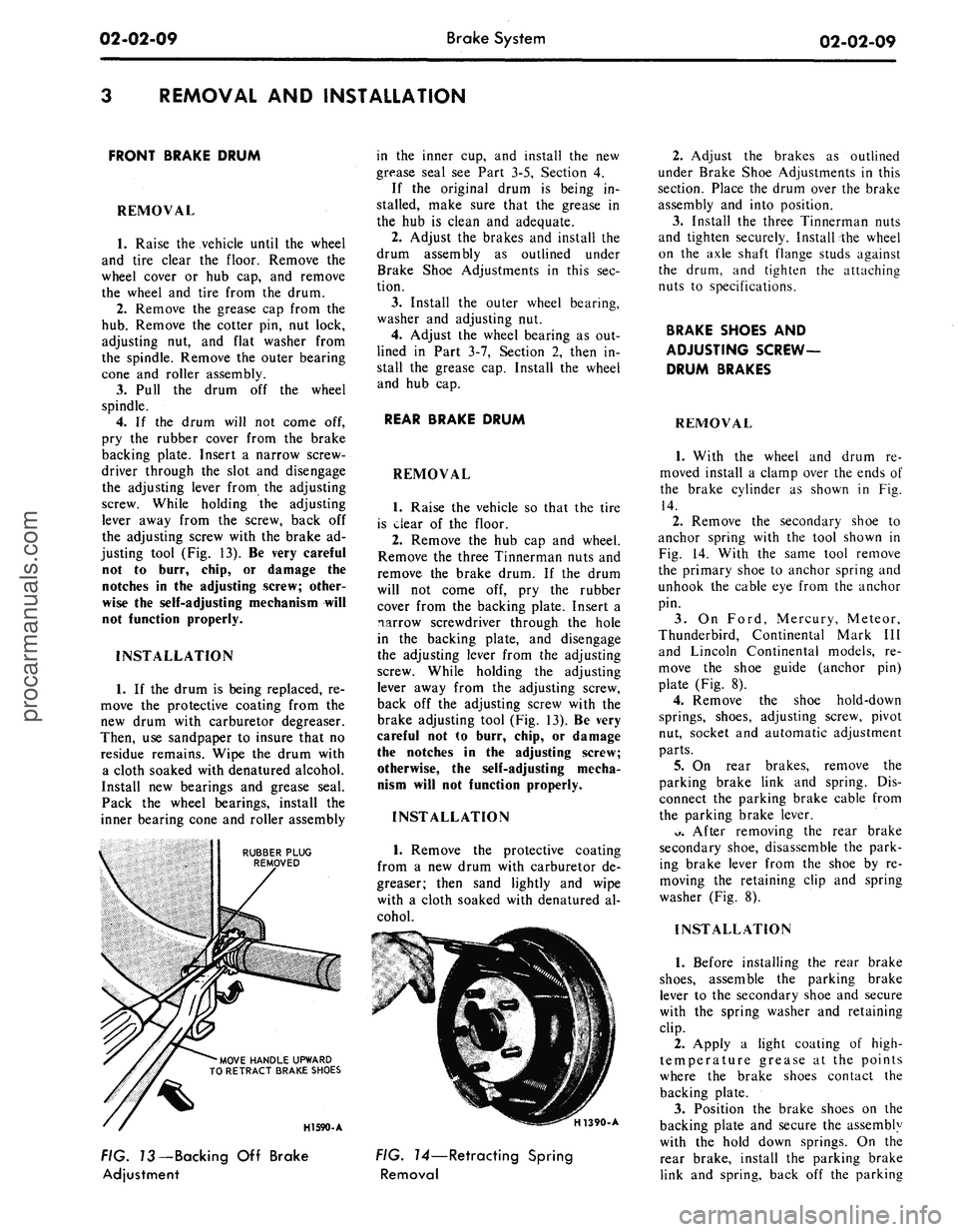
the adjusting screw with the brake ad-
justing tool (Fig. 13). Be very careful
not to burr, chip, or damage the
notches in the adjusting screw; other-
wise the self-adjusting mechanism will
not function properly.
INSTALLATION
1.
If the drum is being replaced, re-
move the protective coating from the
new drum with carburetor degreaser.
Then, use sandpaper to insure that no
residue remains. Wipe the drum with
a cloth soaked with denatured alcohol.
Install new bearings and grease seal.
Pack the wheel bearings, install the
inner bearing cone and roller assembly
RUBBER PLUG
REMOVED
'MOVE HANDLE UPWARD
TO RETRACT BRAKE SHOES
in the inner cup, and install the new
grease seal see Part 3-5, Section 4.
If the original drum is being in-
stalled, make sure that the grease in
the hub is clean and adequate.
2.
Adjust the brakes and install the
drum assembly as outlined under
Brake Shoe Adjustments in this sec-
tion.
3.
Install the outer wheel bearing,
washer and adjusting nut.
4.
Adjust the wheel bearing as out-
lined in Part 3-7, Section 2, then in-
stall the grease cap. Install the wheel
and hub cap.
REAR BRAKE DRUM
REMOVAL
1.
Raise the vehicle so that the tire
is clear of the floor.
2.
Remove the hub cap and wheel.
Remove the three Tinnerman nuts and
remove the brake drum. If the drum
will not come off, pry the rubber
cover from the backing plate. Insert a
narrow screwdriver through the hole
in the backing plate, and disengage
the adjusting lever from the adjusting
screw. While holding the adjusting
lever away from the adjusting screw,
back off the adjusting screw with the
brake adjusting tool (Fig. 13). Be very
careful not to burr, chip, or damage
the notches in the adjusting screw;
otherwise, the self-adjusting mecha-
nism will not function properly.
INSTALLATION
1.
Remove the protective coating
from a new drum with carburetor de-
greaser; then sand lightly and wipe
with a cloth soaked with denatured al-
cohol.
HI 590-A
H1390-A
FIG. 73—Backing Off Brake
Adjustment
FIG. 14—Retracting Spring
Removal
2.
Adjust the brakes as outlined
under Brake Shoe Adjustments in this
section. Place the drum over the brake
assembly and into position.
3.
Install the three Tinnerman nuts
and tighten securely. Install the wheel
on the axle shaft flange studs against
the drum, and tighten the attaching
nuts to specifications.
BRAKE SHOES AND
ADJUSTING SCREW-
DRUM BRAKES
REMOVAL
1.
With the wheel and drum re-
moved install a clamp over the ends of
the brake cylinder as shown in Fig.
14.
2.
Remove the secondary shoe to
anchor spring with the tool shown in
Fig. 14. With the same tool remove
the primary shoe to anchor spring and
unhook the cable eye from the anchor
pin.
3.
On Ford, Mercury, Meteor,
Thunderbird, Continental Mark III
and Lincoln Continental models, re-
move the shoe guide (anchor pin)
plate (Fig. 8).
4.
Remove the shoe hold-down
springs, shoes, adjusting screw, pivot
nut, socket and automatic adjustment
parts.
5.
On rear brakes, remove the
parking brake link and spring. Dis-
connect the parking brake cable from
the parking brake lever.
*>.
After removing the rear brake
secondary shoe, disassemble the park-
ing brake lever from the shoe by re-
moving the retaining clip and spring
washer (Fig. 8).
INSTALLATION
1.
Before installing the rear brake
shoes,
assemble the parking brake
lever to the secondary shoe and secure
with the spring washer and retaining
clip.
2.
Apply a light coating of high-
temperature grease at the points
where the brake shoes contact the
backing plate.
3.
Position the brake shoes on the
backing plate and secure the assembly
with the hold down springs. On the
rear brake, install the parking brake
link and spring, back off the parkingprocarmanuals.com
Page 29 of 413
02-02-10
Brake System
02-02-10
brake adjustment then connect the
parking brake cable to the parking
brake lever (Fig. 8).
4.
Install the shoe guide (anchor
pin) plate on the anchor pin when so
equipped.
5.
Place the cable eye over the an-
chor pin with the crimped side toward
the backing plate.
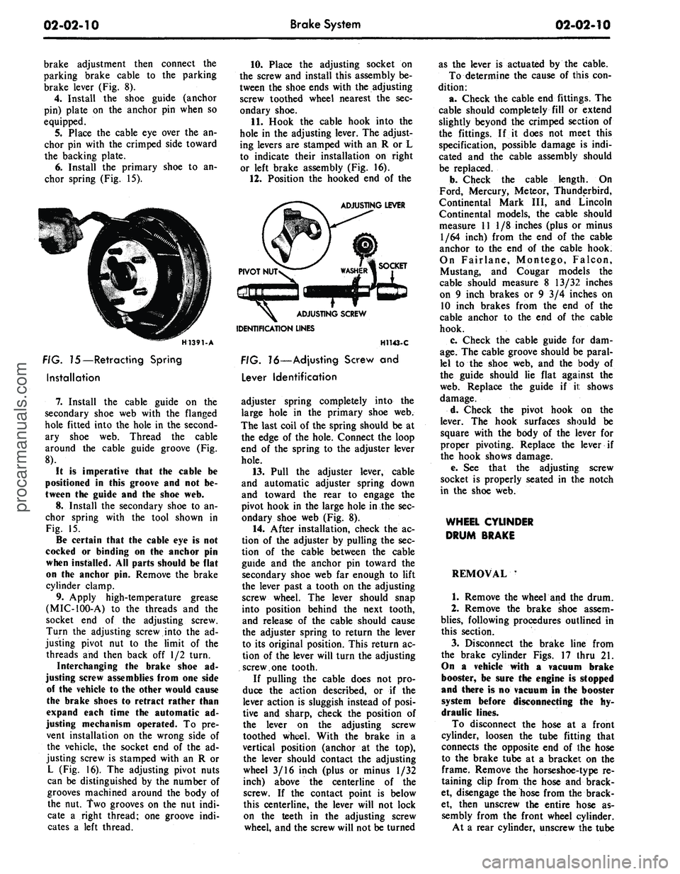
6. Install the primary shoe to an-
chor spring (Fig. 15).
H1391-A
FIG. 75—Retracting Spring
Installation
7.
Install the cable guide on the
secondary shoe web with the flanged
hole fitted into the hole in the second-
ary shoe web. Thread the cable
around the cable guide groove (Fig.
8).
It
is
imperative that
the
cable
be
positioned
in
this groove
and not be-
tween
the
guide
and the
shoe
web.
8.
Install the secondary shoe to an-
chor spring with the tool shown in
Fig. 15.
Be certain that
the
cable
eye is not
cocked
or
binding
on the
anchor
pin
when installed.
All
parts should
be
flat
on
the
anchor
pin.
Remove
the
brake
cylinder clamp.
9. Apply high-temperature grease
(MIC-100-A) to the threads and the
socket end of the adjusting screw.
Turn the adjusting screw into the ad-
justing pivot nut to the limit of the
threads and then back off 1/2 turn.
Interchanging
the
brake shoe
ad-
justing screw assemblies from
one
side
of
the
vehicle
to the
other would cause
the brake shoes
to
retract rather than
expand each time
the
automatic
ad-
justing mechanism operated.
To pre-
vent installation on the wrong side of
the vehicle, the socket end of the ad-
justing screw is stamped with an R or
L (Fig. 16). The adjusting pivot nuts
can be distinguished by the number of
grooves machined around the body of
the nut. Two grooves on the nut indi-
cate a right thread; one groove indi-
cates a left thread.
10.
Place the adjusting socket on
the screw and install this assembly be-
tween the shoe ends with the adjusting
screw toothed wheel nearest the sec-
ondary shoe.
11.
Hook the cable hook into the
hole in the adjusting lever. The adjust-
ing levers are stamped with an R or L
to indicate their installation on right
or left brake assembly (Fig. 16).
12.
Position the hooked end of the
ADJUSTING LEVER
IDENTIFICATION LINES
H1143-C
FIG. 16—Adjusting Screw
and
Lever Identification
adjuster spring completely into the
large hole in the primary shoe web.
The last coil of the spring should be at
the edge of the hole. Connect the loop
end of the spring to the adjuster lever
hole.
13.
Pull the adjuster lever, cable
and automatic adjuster spring down
and toward the rear to engage the
pivot hook in the large hole in the sec-
ondary shoe web (Fig. 8).
14.
After installation, check the ac-
tion of the adjuster by pulling the sec-
tion of the cable between the cable
guide and the anchor pin toward the
secondary shoe web far enough to lift
the lever past a tooth on the adjusting
screw wheel. The lever should snap
into position behind the next tooth,
and release of the cable should cause
the adjuster spring to return the lever
to its original position. This return ac-
tion of the lever will turn the adjusting
screw.one tooth.
If pulling the cable does not pro-
duce the action described, or if the
lever action is sluggish instead of posi-
tive and sharp, check the position of
the lever on the adjusting screw
toothed wheel. With the brake in a
vertical position (anchor at the top),
the lever should contact the adjusting
wheel 3/16 inch (plus or minus 1/32
inch) above the centerline of the
screw. If the contact point is below
this centerline, the lever will not lock
on the teeth in the adjusting screw
wheel, and the screw will not be turned
as the lever is actuated by the cable.
To determine the cause of this con-
dition:
a. Check the cable end fittings. The
cable should completely fill or extend
slightly beyond the crimped section of
the fittings. If it does not meet this
specification, possible damage is indi-
cated and the cable assembly should
be replaced.
b.
Check the cable length. On
Ford, Mercury, Meteor, Thunderbird,
Continental Mark III, and Lincoln
Continental models, the cable should
measure 11 1/8 inches (plus or minus
1/64 inch) from the end of the cable
anchor to the end of the cable hook.
On Fairlane, Montego, Falcon,
Mustang, and Cougar models the
cable should measure 8 13/32 inches
on 9 inch brakes or 9 3/4 inches on
10 inch brakes from the end of the
cable anchor to the end of the cable
hook.
c. Check the cable guide for dam-
age.
The cable groove should be paral-
lel to the shoe web, and the body of
the guide should lie flat against the
web.
Replace the guide if it shows
damage.
d. Check the pivot hook on the
lever. The hook surfaces should be
square with the body of the lever for
proper pivoting. Replace the lever if
the hook shows damage.
e. See that the adjusting; screw
socket is properly seated in the notch
in the shoe web.
WHEEL CYLINDER
DRUM BRAKE
REMOVAL '
1.
Remove the wheel and the drum.
2.
Remove the brake shoe assem-
blies,
following procedures outlined in
this section.
3.
Disconnect the brake line from
the brake cylinder Figs. 17 thru 21.
On
a
vehicle with
a
vacuum brake
booster,
be
sure
the
engine
is
stopped
and there
is no
vacuum
in the
booster
system before disconnecting
the hy-
draulic lines.
To disconnect the hose at a front
cylinder, loosen the tube fitting that
connects the opposite end of the hose
to the brake tube at a bracket on the
frame. Remove the horseshoe-type re-
taining clip from the hose and brack-
et, disengage the hose from the brack-
et, then unscrew the entire hose as-
sembly from the front wheel cylinder.
At a rear cylinder, unscrew the tubeprocarmanuals.com
Page 34 of 413
BOLT-381877
TUBE-2267
BRACKET-2A448
TUBE-2268
VIEW IN CIRCLE X
TYPICAL 3 PLACES
TUBE ASSEMBLY-2B162
TUBE ASSEMBLY-2264
TUBE ASSEMBLY-2263
TUBE-2267
BEND CLIPS TO RETAIN
TUBES AT ASSEMBLY
5 PLACES
CHECK BRAKE HOSE CLEARANCE
TO ALL COMPONENTS IN METAL/METAL
JOUNCE AND METAL/METAL REBOUND
TUBE-2268
PROPORTIONING
VALVE ASSEMBLY
BRACKET-2B266
BOOSTER ASSEMBLY-2B195
PULLOUT WHILE BLEEDING
BRAKE SYSTEM-USE CARE
NOT TO BEND PIN
TUBE-2420
DIFFERENTIAL VALVE-C8VA
VIEW IN CIRCLE M
TUBE-2A280
TUBE-2A280
PRESSURE DIFFERENTIAL
VALVE ASSEMBLY-C8VA-2B328-C
TUBE ASSEMBLY-2264
BRACKET-2082 R.H.
-2AO56 L.H.
CLIP-97502
2 REQUIRED
357444-S 2 REQUIRED
TO CALIPER ASSEMBLY
HOSE-2B171 R.H.
-2B218 L.H.
VIEWN
HOSE-2A448
TUBE-2A280
VIEWP
SHIELD-2A337
VIEW IN CIRCLE S
TYPICAL 4 PLACES
TUBE-2A280
VIEWR
V1EWU
VIEWV
WASHER-2149 2 REQUIRED
TUBE-2B166 R.H.
-2B168 L.H.
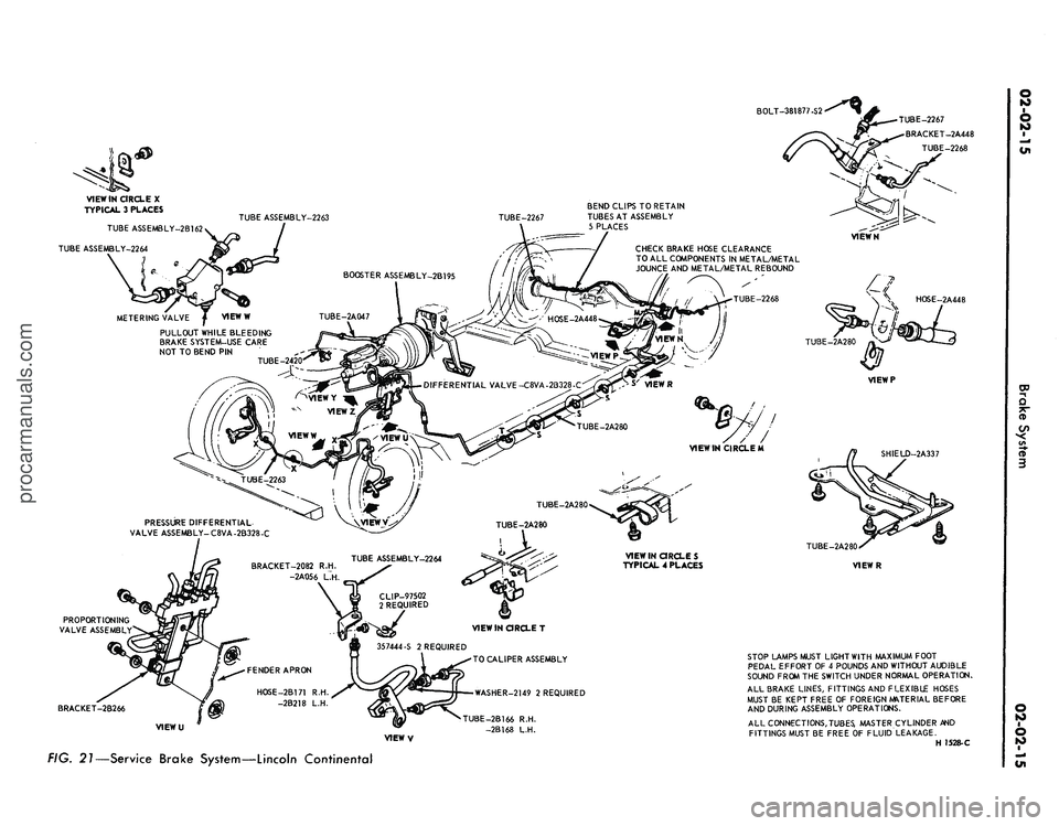
STOP LAMPS MUST LIGHT WITH MAXIMUM FOOT
PEDAL EFFORT OF 4 POUNDS AND WITHOUT AUDIBLE
SOUND FROM THE SWITCH UNDER NORMAL OPERATION.
ALL BRAKE LINES, FITTINGS AND FLEXIBLE HOSES
MUST BE KEPT FREE OF FOREIGN MATERIAL BEFORE
AND DURING ASSEMBLY OPERATIONS.
ALL CONNECT
IONS,
TUBES,
MASTER CYLINDER AND
FITTINGS MUST BE FREE OF FLUID LEAKAGE.
H 1528-C
FIG. 21—Service Brake System—Lincoln Continentalprocarmanuals.com
Page 38 of 413
02-02-19
Brake System
02-02-19
that the tabs on the shoe flanges seat
fully against the caliper bridges (Fig.
25).
2.
Install the caliper splash shield
and secure the shield to the caliper
with two retaining bolts (Fig. 4).
3.
Pump the brake pedal several
times until a firm pedal is obtained
and the shoe and lining assemblies are
properly seated.
4.
Install the wheel and tire assem-
bly on the hub and rotor assembly.
5.
Check and refill the master cyl-
inder reservoir with specified brake
fluid as required.
6. Road test the car.
It should not be necessary to bleed
the system after a shoe and lining re-
placement.
FRONT WHEEL HUB AND
ROTOR ASSEMBLY-
DISC BRAKES
REMOVAL
1.
Remove the wheel and tire from
the hub (Figs. 23 and 24). Be careful
to avoid damage or interference with
the bleeder screw fitting. On Lincoln
Continental models be careful to avoid
damage to the caliper splash shield or
transfer tube.
2.
Remove the caliper assembly
from the spindle and the rotor. If the
caliper does not require servicing, it is
not necessary to disconnect the brake
hose or remove the caliper from the
vehicle. Position the caliper out of the
way, and support it with a wire to
avoid damaging the caliper or stretch-
ing the hose. Insert a clean cardboard
spacer between the linings to prevent
the piston from coming out of the cyl-
inder bore while the caliper is re-
moved.
Handle the rotor and caliper assem-
blies in such a way as to avoid defor-
mation of the rotor and nicking,
scratching or contamination of the
brake linings.
3.
Remove the grease cap from the
hub.
Remove the cotter pin, nut lock,
adjusting nut, and flat washer from
the spindle. Remove the outer bearing
cone and roller assembly.
4.
Remove the hub and rotor as-
sembly from the spindle.
INSTALLATION
1.
If the rotor is being replaced, re-
move the protective coating from the
new rotor with carburetor degreaser.
Pack a new set of bearings with speci-
fied grease (M-1C75B), and install the
inner bearing cone and roller assembly
in the inner cup. Pack grease lightly
between the lips of a new grease seal
and install the seal (Figs. 23 and 24).
If the original rotor is being in-
stalled, make sure that the grease in
the hub is clean and adequate, that
the inner bearing and grease seal are
lubricated and in good condition, and
that the rotor braking surfaces are
clean.
2.
Install the hub and rotor assem-
bly on the spindle.
3.
Lubricate and install the outer
wheel bearing, washer and adjusting
nut.
4.
Adjust the wheel bearings to
specification, and then install the nut
lock, cotter pin, and grease cap. The
wheel bearing adjustment is especially
important with disc brakes.
5. Mount the caliper assembly on
the spindle following the Disc Brake
Caliper Assembly Installation proce-
dure in this section.
DISC BRAKE ROTOR
SPLASH SHIELD
REMOVAL
1.
Remove the caliper and the hub
and rotor assembly as outlined under
Removal in the foregoing procedure
(it is not necessary to disconnect hy-
draulic connections).
2.
Remove the three bolts that at-
tach the splash shield to the spindle,
and remove the shield (Figs. 23 and
24).
3.
Remove and discard the splash
shield to spindle gasket.
INSTALLATION
1.
Install a new splash shield to
spindle gasket.
2.
If the shield is bent, straighten it
out before installation. Position the
shield to the mounting bracket, install
the attaching bolts, nuts and torque
them to specification.
3.
Install the hub and rotor assem-
bly and the caliper as outlined under
Installation in the foregoing proce-
dure.
DUAL MASTER CYLINDER—
NON POWER BRAKES
FORD, MERCURY
AND METEOR
Removal
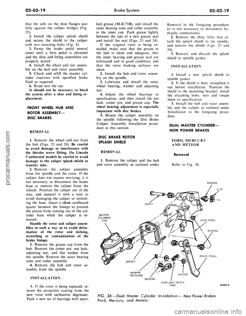
Refer to Fig. 26.
BUSHING
HAIRPIN
RETAINER
BUSHING
STOPLIGHT SWITCH
13480
HI 637-A
FIG. 26—Dual Master Cylinder Installation— Non Power Brakes
Ford,
Mercury, and Meteorprocarmanuals.com