specifications FORD MUSTANG 1969 Volume One Chassis
[x] Cancel search | Manufacturer: FORD, Model Year: 1969, Model line: MUSTANG, Model: FORD MUSTANG 1969Pages: 413, PDF Size: 75.81 MB
Page 3 of 413
FOREWORD
The five volumes of
this
shop manual provide the Service Technician
with complete information for the proper servicing of all the 1969 line
of Ford Passenger Cars.
The information is grouped according to the type of work being per-
formed,
such as frequently performed adjustments and repairs, in-
vehicle adjustments, major repair, etc. Specifications, maintenance
information and recommended special tools are
included.
The descriptions and specifications in this manual were in effect at the
time this manual was approved for printing. Ford Motor Company
reserves the right to discontinue models at any time, or change specifi-
cations
or design, without notice and without incurring obligation.
SERVICE PUBLICATIONSprocarmanuals.com
Page 12 of 413
02-01-01
02-01-01
GROUP
2
PART
2-1
PAGE
General Brake Service 02-01-01
PART
2-2
Brake System 02-02-01
PART
2-3
Specifications
PAGE
02-03-01
Part
2-1
General Brake Service
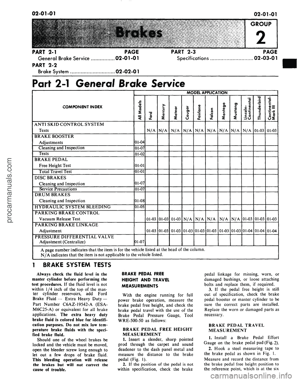
COMPONENT INDEX
ANTI SKID CONTROL SYSTEM
Tests
BRAKE BOOSTER
Adjustments
Cleaning
and
Inspection
Tests
BRAKE PEDAL
Free Height Test
Total Travel Test
DISC BRAKES
Cleaning
and
Inspection
Service Precautions
DRUM BRAKES
Cleaning
and
Inspection
HYDRAULIC SYSTEM BLEEDING
PARKING BRAKE CONTROL
Vacuum Release Test
PARKING BRAKE LINKAGE
Adjustment
PRESSURE DIFFERENTIAL VALVE
Adjustment (Centralize)
MODEL APPLICATION
All
Models
01-04
01-07
01-02
01-01
01-01
01-07
01-07
01-08
01-05
01-07
Ford
N/A
01-03
01-03
Mercury
N/A
01-03
01-03
Meteor
N/A
01-03
01-03
Cougar
N/A
N/A
01-03
Fairlane
N/A
N/A
01-03
F
alcon
N/A
N/A
01-03
Montego
N/A
N/A
01-03
Mustang
N/A
N/A
01-03
Lincoln-
Continental
N/A
01-03
01-04
Thunderbird
01-03
01-03
01-04
Continental-
Mark III
01-03
01-03
01-04
A page number indicates that the item
is for the
vehicle listed
at
the head
of the
column.
N/A indicates that the item
is not
applicable
to
the vehicle listed.
1 BRAKE SYSTEM TESTS
Always check
the
fluid level
in the
master cylinder before performing
the
test procedures.
If the
fluid level
is not
within
1/4
inch
of the top of the mas-
ter cylinder reservoirs,
add
Ford
Brake Fluid
—
Extra Heavy Duty —
Part Number C6AZ-19542-A
(ESA-
M6C25-A)
or
equivalent
for all
brake
applications.
The
extra heavy duty
brake fluid
is
colored blue
for
identifi-
cation purposes.
Do not mix low tem-
perature brake fluids with
the
speci-
fied brake fluid.
Should
one of the
wheel brakes
be
locked
and the
vehicle must
be
moved,
open
the
bleeder screw long enough
to
let
out a few
drops
of
brake fluid.
This bleeding operation will release
the brakes
but
will
not
correct
the
cause
of
trouble.
BRAKE PEDAL FREE
HEIGHT
AND
TRAVEL
MEASUREMENTS
With
the
engine running
for
full
power brake operation, measure
the
brake pedal free height,
and
check
the
brake pedal travel with
the use of the
Brake Pedal Pressure Gauge, Tool
WRE-5OO-5O
as
follows:
BRAKE PEDAL FREE HEIGHT
MEASUREMENT
1.
Insert
a
slender, sharp pointed
prod through
the
carpet
and
sound
deadener
to the
dash panel metal
and
measure
the
distance
to the
brake
pedal
(Fig. 1).
2.
If the
position
of the
pedal
is not
within specification, check
the
brake
pedal linkage
for
missing, worn,
or
damaged bushings,
or
loose attaching
bolts
and
replace them,
if
required.
3.
If the
pedal free height
is
still
out
of
specification, check
the
brake
pedal booster
or
master cylinder
to be
sure
the
correct parts
are
installed.
Replace
the
worn
or
damaged parts
as
necessary.
BRAKE PEDAL TRAVEL
MEASUREMENT
1.
Install
a
Brake Pedal Effort
Gauge
on the
brake pedal
pad
(Fig. 2).
2.
Hook
a
steel measuring tape
to
the brake pedal
as
shown
in Fig. 1.
Measure
and
record
the
distance from
the brake pedal free height position
to
the reference point, which
is at the six
procarmanuals.com
Page 28 of 413
02-02-09
Brake System
02-02-09
REMOVAL AND INSTALLATION
FRONT BRAKE DRUM
REMOVAL
1.
Raise the vehicle until the wheel
and tire clear the floor. Remove the
wheel cover or hub cap, and remove
the wheel and tire from the drum.
2.
Remove the grease cap from the
hub.
Remove the cotter pin, nut lock,
adjusting nut, and flat washer from
the spindle. Remove the outer bearing
cone and roller assembly.
3.
Pull the drum off the wheel
spindle.
4.
If the drum will not come off,
pry the rubber cover from the brake
backing plate. Insert a narrow screw-
driver through the slot and disengage
the adjusting lever from the adjusting
screw. While holding the adjusting
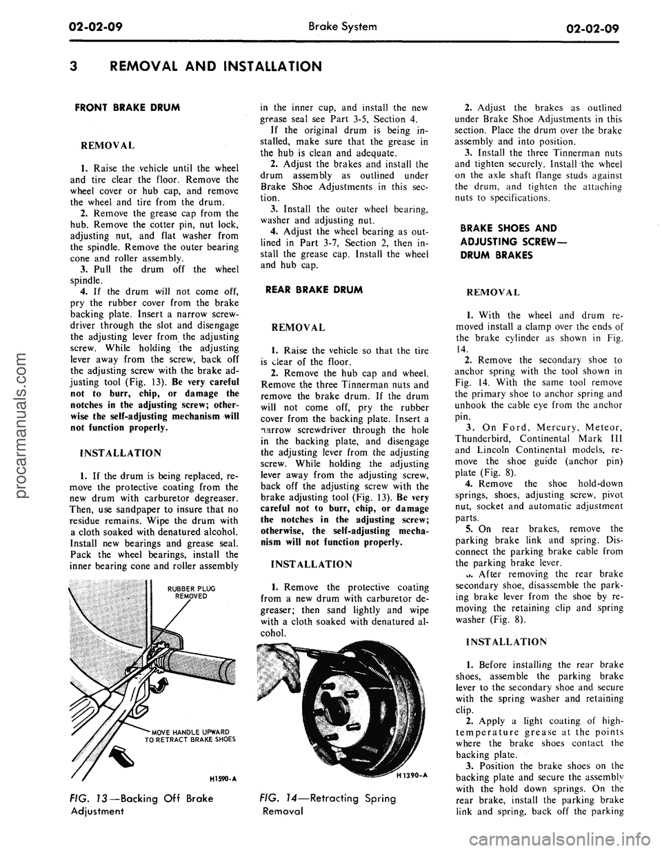
lever away from the screw, back off
the adjusting screw with the brake ad-
justing tool (Fig. 13). Be very careful
not to burr, chip, or damage the
notches in the adjusting screw; other-
wise the self-adjusting mechanism will
not function properly.
INSTALLATION
1.
If the drum is being replaced, re-
move the protective coating from the
new drum with carburetor degreaser.
Then, use sandpaper to insure that no
residue remains. Wipe the drum with
a cloth soaked with denatured alcohol.
Install new bearings and grease seal.
Pack the wheel bearings, install the
inner bearing cone and roller assembly
RUBBER PLUG
REMOVED
'MOVE HANDLE UPWARD
TO RETRACT BRAKE SHOES
in the inner cup, and install the new
grease seal see Part 3-5, Section 4.
If the original drum is being in-
stalled, make sure that the grease in
the hub is clean and adequate.
2.
Adjust the brakes and install the
drum assembly as outlined under
Brake Shoe Adjustments in this sec-
tion.
3.
Install the outer wheel bearing,
washer and adjusting nut.
4.
Adjust the wheel bearing as out-
lined in Part 3-7, Section 2, then in-
stall the grease cap. Install the wheel
and hub cap.
REAR BRAKE DRUM
REMOVAL
1.
Raise the vehicle so that the tire
is clear of the floor.
2.
Remove the hub cap and wheel.
Remove the three Tinnerman nuts and
remove the brake drum. If the drum
will not come off, pry the rubber
cover from the backing plate. Insert a
narrow screwdriver through the hole
in the backing plate, and disengage
the adjusting lever from the adjusting
screw. While holding the adjusting
lever away from the adjusting screw,
back off the adjusting screw with the
brake adjusting tool (Fig. 13). Be very
careful not to burr, chip, or damage
the notches in the adjusting screw;
otherwise, the self-adjusting mecha-
nism will not function properly.
INSTALLATION
1.
Remove the protective coating
from a new drum with carburetor de-
greaser; then sand lightly and wipe
with a cloth soaked with denatured al-
cohol.
HI 590-A
H1390-A
FIG. 73—Backing Off Brake
Adjustment
FIG. 14—Retracting Spring
Removal
2.
Adjust the brakes as outlined
under Brake Shoe Adjustments in this
section. Place the drum over the brake
assembly and into position.
3.
Install the three Tinnerman nuts
and tighten securely. Install the wheel
on the axle shaft flange studs against
the drum, and tighten the attaching
nuts to specifications.
BRAKE SHOES AND
ADJUSTING SCREW-
DRUM BRAKES
REMOVAL
1.
With the wheel and drum re-
moved install a clamp over the ends of
the brake cylinder as shown in Fig.
14.
2.
Remove the secondary shoe to
anchor spring with the tool shown in
Fig. 14. With the same tool remove
the primary shoe to anchor spring and
unhook the cable eye from the anchor
pin.
3.
On Ford, Mercury, Meteor,
Thunderbird, Continental Mark III
and Lincoln Continental models, re-
move the shoe guide (anchor pin)
plate (Fig. 8).
4.
Remove the shoe hold-down
springs, shoes, adjusting screw, pivot
nut, socket and automatic adjustment
parts.
5.
On rear brakes, remove the
parking brake link and spring. Dis-
connect the parking brake cable from
the parking brake lever.
*>.
After removing the rear brake
secondary shoe, disassemble the park-
ing brake lever from the shoe by re-
moving the retaining clip and spring
washer (Fig. 8).
INSTALLATION
1.
Before installing the rear brake
shoes,
assemble the parking brake
lever to the secondary shoe and secure
with the spring washer and retaining
clip.
2.
Apply a light coating of high-
temperature grease at the points
where the brake shoes contact the
backing plate.
3.
Position the brake shoes on the
backing plate and secure the assembly
with the hold down springs. On the
rear brake, install the parking brake
link and spring, back off the parkingprocarmanuals.com
Page 35 of 413
02-02-16
Brake System
02-02-16
fitting that connects the tube to the
cylinder. Do not pull the metal tube
away from the cylinder. Pulling the
tube out of the cylinder connection
will bend the metal tube and make in-
stallation difficult. The tube will sepa-
rate from the cylinder when the cylin-
der is removed from the backing
plate.
4.
On all except the front wheels on
Ford, Mercury, and Meteor models,
remove the wheel cylinder attaching
bolts and lock washers and remove the
cylinder. On the front wheel of Ford,
Mercury and Meteor models, remove
the nut and washer that attaches the
cylinder to the anchor pin. Remove
the cylinder from the anchor pin.
INSTALLATION
Wipe the end(s) of the hydraulic
line to remove any foreign matter be-
fore making connections.
1.
On all models except Ford, Mer-
cury and Meteor, to install a front
wheel cylinder, position the cylinder to
the backing plate. Install the two lock
washers and attaching bolts. Torque
them to specifications.
On Ford, Mercury and Meteor
models, to install a front wheel cylin-
der, position the cylinder on the an-
chor pin against the backing plate. In-
stall the washer and cylinder attaching
nut on the anchor pin, and torque it
to specification. Lock the washer re-
tainer securely.
2.
Install a new copper gasket over
the hose fitting. Thread the hose into
the cylinder and tighten it to specified
torque.
3.
Engage the opposite end of the
hose to the bracket on the frame. In-
stall the horseshoe-type retaining clip,
and connect the brake tube to the
hose with the tube fitting nut. Tighten
the nut to specification with tool
1112-144.
4.
To install a rear wheel cylinder,
place the rear wheel cylinder into po-
sition. Enter the tubing into the cylin-
der, and start the tube fitting nut into
the threads of the cylinder.
5.
Secure the cylinder to the back-
ing plate by installing the attaching
bolts and lock washers.
6. Tighten the tube fitting nut to
specification with tool 1112-144.
7.
Install the links in the ends of
the wheel cylinder, install the shoes
and adjuster assemblies, and adjust
the shoes as outlined in this section.
8. Adjust the brakes (Part 2-2, Sec-
tion 2). Install the brake drum and
wheel. Bleed the brakes and centralize
the differential valve as outlined in
Part 2-1, Section 2.
BRAKE BACKING PLATE
DRUM BRAKE
REMOVAL
1.
Remove the wheel and brake
drum. Disconnect the brake line from
the brake cylinder.
2.
Remove the brake shoe and ad-
juster assemblies and the wheel cylin-
der as outlined in this section. On the
rear wheels, disconnect the parking
brake lever from the cable.
3.
If the rear backing plate is being
replaced, remove the axle shaft from
the applicable rear axle as outlined in
Group 4, Part 4-2— Rear Axle, Sec-
tion 2, disengage parking brake cable
retainer from backing plate. Remove
the backing plate and gasket.
If the front backing plate is being
replaced, remove the bolts and nuts
that secure the backing plate to the
front wheel spindle and remove the
plate and gasket.
INSTALLATION
If a rear backing plate is to be re-
placed, position a new rear backing
plate and gasket on the attaching
bolts in the axle housing flange. Insert
parking brake cable into backing plate
and secure retaining fingers. Install
the rear axle shaft for applicable rear
axle.
Refer to Group 4, Part 4-2 —
Rear Axle, Section 2 for the proper
installation procedure.
1.
If the front brake backing plate
is to be replaced, position a new front
backing plate and gasket to the wheel
spindle and install the attaching bolts
and nuts.
2.
Install the wheel cylinder and
connect the brake line as outlined in
this section.
3.
Install the brake shoe and ad-
juster assemblies as outlined in this
section. On a rear brake, connect the
parking brake cable to the lever.
4.
Adjust the brake shoes (Section
2),
and install the brake drums and
wheels. Bleed the brake system and
centralize the differential valve as out-
lined in Part 2-1, Section 2.
DISC BRAKE CALIPER
ASSEMBLY
ALL MODELS EXCEPT
LINCOLN CONTINENTAL
Removal
Refer to Figs. 22 and 23.
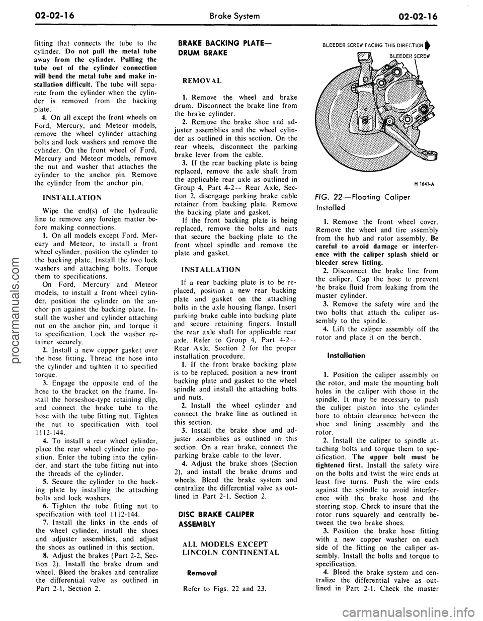
BLEEDER SCREW FACING THIS DIRECTION^
BLEEDER SCREW
H 1641-A
FIG. 22—Floating Caliper
Installed
1.
Remove the front wheel cover.
Remove the wheel and tire assembly
from the hub and rotor assembly. Be
careful to avoid damage or interfer-
ence with the caliper splash shield or
bleeder screw fitting.
2.
Disconnect the brake line from
the caliper. Cap the hose to prevent
*he brake fluid from leaking from the
master cylinder.
3.
Remove the safety wire and the
two bolts that attach the caliper as-
sembly to the spindle.
4.
Lift the caliper assembly off the
rotor and place it on the bench.
Installation
1.
Position the caliper assembly on
the rotor, and mate the mounting bolt
holes in the caliper with those in the
spindle. It may be necessary to push
the caliper piston into the cylinder
bore to obtain clearance between the
shoe and lining assembly and the
rotor.
2.
Install the caliper to spindle at-
taching bolts and torque them to spe-
cification. The upper bolt must be
tightened first. Install the safety wire
on the bolts and twist the wire ends at
least five turns. Push the wire ends
against the spindle to avoid interfer-
ence with the brake hose and the
steering stop. Check to insure that the
rotor runs squarely and centrally be-
tween the two brake shoes.
3.
Position the brake hose fitting
with a new copper washer on each
side of the fitting on the caliper as-
sembly. Install the bolts and torque to
specification.
4.
Bleed the brake system and cen-
tralize the differential valve as out-
lined in Part 2-1. Check the masterprocarmanuals.com
Page 37 of 413
02-02-18
Brake System
02-02-18
the brake hose connector
and
bracket
assembly.
3.
Remove
the two
bolts retaining
the brake hose bracket
and
caliper
as-
sembly
to the
spindle. Take care
to
avoid loosening
the
bridge bolts that
hold
the two
halves
of the
caliper
to-
gether.
4.
Lift
the
caliper assembly
off the
rotor
and
place
it on the
bench.
Installation
1.
If the
caliper assembly
is to be
replaced, transfer
the
steel tubing
and
the bleeder screw
to the new
caliper.
2.
Position
the
caliper assembly
on
the rotor,
and
mate
the
mounting bolt
holes
in the
caliper with those
in the
spindle.
It may be
necessary
to
push
the caliper pistons into
the
cylinder
bores
to
obtain clearance between
the
shoe
and
lining assembly
and the
rotor.
The
shoe
and
lining assemblies
should
be
seated properly
on the
bridges.
3.
Install
the
caliper
to
spindle
re-
taining bolts
and
torque them
to
spec-
ification. Check
to
insure that
the
rotor runs squarely
and
centrally
be-
tween
the two
halves
of the
caliper.
These should
be
approximately 0.090-
0.120 inch clearance between
the
cali-
per
and the
rotor outside diameter
(Fig.
6).
4.
Position
the
steel transfer tube
brake hose bracket
and
caliper assem-
bly
to the
spindle. Install
the
retaining
bolts then torque them
to
specifica-
tion.
5.
Connect
the
front wheel steel
transfer tube from
the
caliper
to the
front brake hose connector. Check
the
hose
for
proper installation
(Fig. 21).
6. Bleed
the
brake system
and cen-
tralize
the
differential valve
as out-
lined
in
Part
2-1.
Check
the
master
cylinder fluid level
and add the
speci-
fied fluid,
as
required. Pump
the
brake pedal several times
to
actuate
the piston seals
and to
position
the
shoe
and
lining assemblies.
7.
Install
the
wheel
and
tire assem-
bly
and the
wheel cover.
8. Road test
the
vehicle.
DISC BRAKE SHOE
AND
LINING
ALL MODELS EXCEPT
LINCOLN CONTINENTAL
Removal
1.
Remove
the
wheel
and
tire from
the
hub and
rotor assembly.
2.
Remove
the
caliper from
the ve-
hicle following
the
procedures outlined
under Disc Brake Caliper Assembly.
3.
To
facilitate removal
of the
cali-
per assemblies,
the
piston
may
have
to
be pushed into
its
bore. Apply
a
steady inward pressure against
the
inner shoe
and
lining assembly. Main-
tain
the
pressure
for at
least
a
minute.
4.
Slide
the two
outer shoe retain-
ing clips
off the
retaining pins
(Fig.
23).
5.
Remove
the two
retaining pins
from
the
outer shoe, then remove
the
shoe from
the
stationary caliper.
6. Slide
the
inner brake shoe
out-
ward until
it is
free
of the
hold-down
springs, then remove
the
brake shoe.
7.
Remove
the
caliper locating pins
and stabilizer attaching bolts, then
re-
move
and
discard
the
stabilizer
or sta-
bilizers.
8. Remove
the
locating
pin
insula-
tors from
the
anchor plate.
Installation
When installing
new
shoes
and lin-
ings
it
will
be
necessary
to
force
the
piston
to the
bottom
of its
bore.
Apply sufficient pressure
to
overcome
the grip
of the
piston seal
on the pis-
ton.
1.
Install
new
caliper locating
pin
insulators
in the
anchor plate.
2.
Position
the
caliper assembly
in
the anchor plate.
3.
Position
the new
stabilizer
or
stabilizers
and
install
the
caliper locat-
ing pins
to
engage approximately four
threads.
If
the
caliper locating pins
are
rust-
ed
or
corroded they should
be re-
placed.
Apply water
or
isopropyl alcohol
to
the caliper locating pins before instal-
lation.
Oil or
grease must
not be
used
on
the
locating pins.
4.
Position
the
outer brake shoe
on
the caliper
and
install
the two
retain-
ing pins
and
clips.
5.
Install
the
inner brake shoe
so
that
the
ears
of
shoe
are on top of the
anchor plate bosses
and
under
the
shoe hold-down springs.
6. Position
the
shoe
and
lining
assemblies
so
that
the
caliper assem-
bly
can be
placed over
the
rotor.
Ro-
tate
a
hammer handle between
the lin-
ings
to
reset
the
stabilizers.
7.
Install
the
caliper assembly over
the rotor
and on the
spindle. Install
the
two
caliper attaching bolts,
and
torque them
to
specifications.
The
upper bolt must
be
tightened first.
In-
stall
the
safety wire
and
twist
the
ends
at least five turns. Push
the
wire ends
against
the
spindle
to
avoid interfer-
ence with
the
brake hose
and the
steering stop.
8. With moderate pressure applied
to
the
brake pedal, torque
the
stabiliz-
er attaching screws
and
caliper locat-
ing pins
to
specification.
LINCOLN CONTINENTAL
Removal
1.
Remove
the
wheel
and
tire
as-
sembly from
the hub and
rotor assem-
bly.
Be
careful
to
avoid damage
or in-
terference with
the
caliper splash
shield, bleeder screw fitting
or
transfer
tube.
2.
Remove
the two
bolts that retain
the caliper splash shield,
and
remove
the shield
(Fig. 4).
3.
To
facilitate removal
and
instal-
lation
of the
shoe
and
lining assem-
blies,
the
pistons must
be
pushed into
their bores. Apply
a
steady inward
pressure against each shoe
and
lining
assembly toward
its
respective caliper
housing
on
each side
of the
rotor
(Fig.
6).
Maintain
the
pressure
for at
least
a minute.
If the
pistons will
not go ifi
easily, force them
in
with water pump
pliers.
4.
Grasp
the
metal flange
on the
outer
end of the
shoe with
two
pairs
of pliers
and
pull
the
shoe
out of the
caliper (Fig.
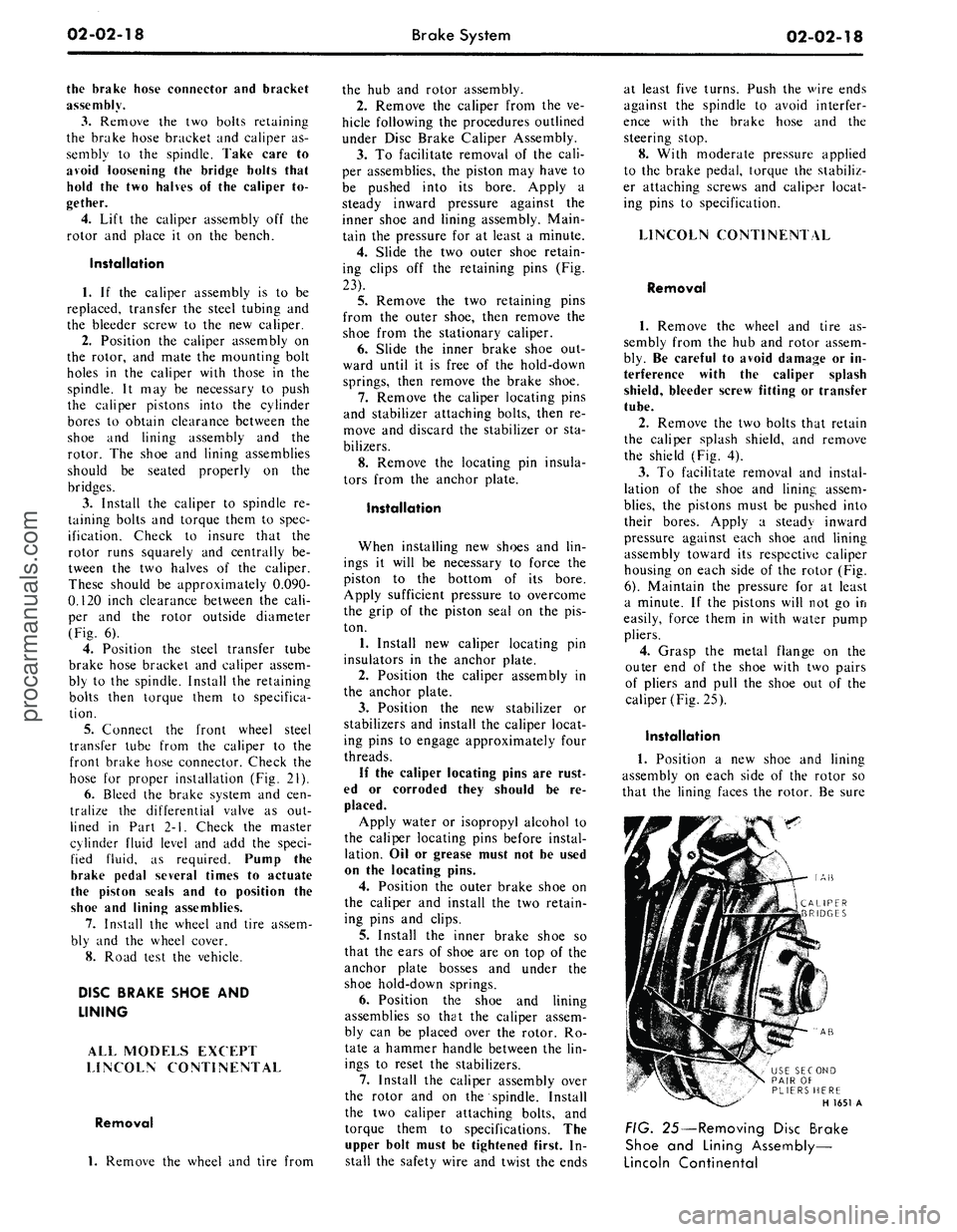
25).
Installation
1.
Position
a new
shoe
and
lining
assembly
on
each side
of the
rotor
so
that
the
lining faces
the
rotor.
Be
sure
AB
AB
USE SECOND
PAIR
OF
PLIERS HERE
H 1651
A
FIG. 25—Removing Disc Brake
Shoe
and
Lining Assembly—
Lincoln Continentalprocarmanuals.com
Page 41 of 413
02-02-22
Brake System
02-02-22
BRAKE VACUUM BOOSTER -2005
AUTOMATIC I
TRANSMISSION
HAIR PIN RETAINER
330699-S2
SPACER
STOP LIGHT SWITCH-13480
STANDARD
TRANSMISSION
BUSHING
BUSHING
PUSH ROD
BRAKE PEDAL ASSEMBLY
CLUTCH
PEDAL
ASSEMBLY
H 1557-C
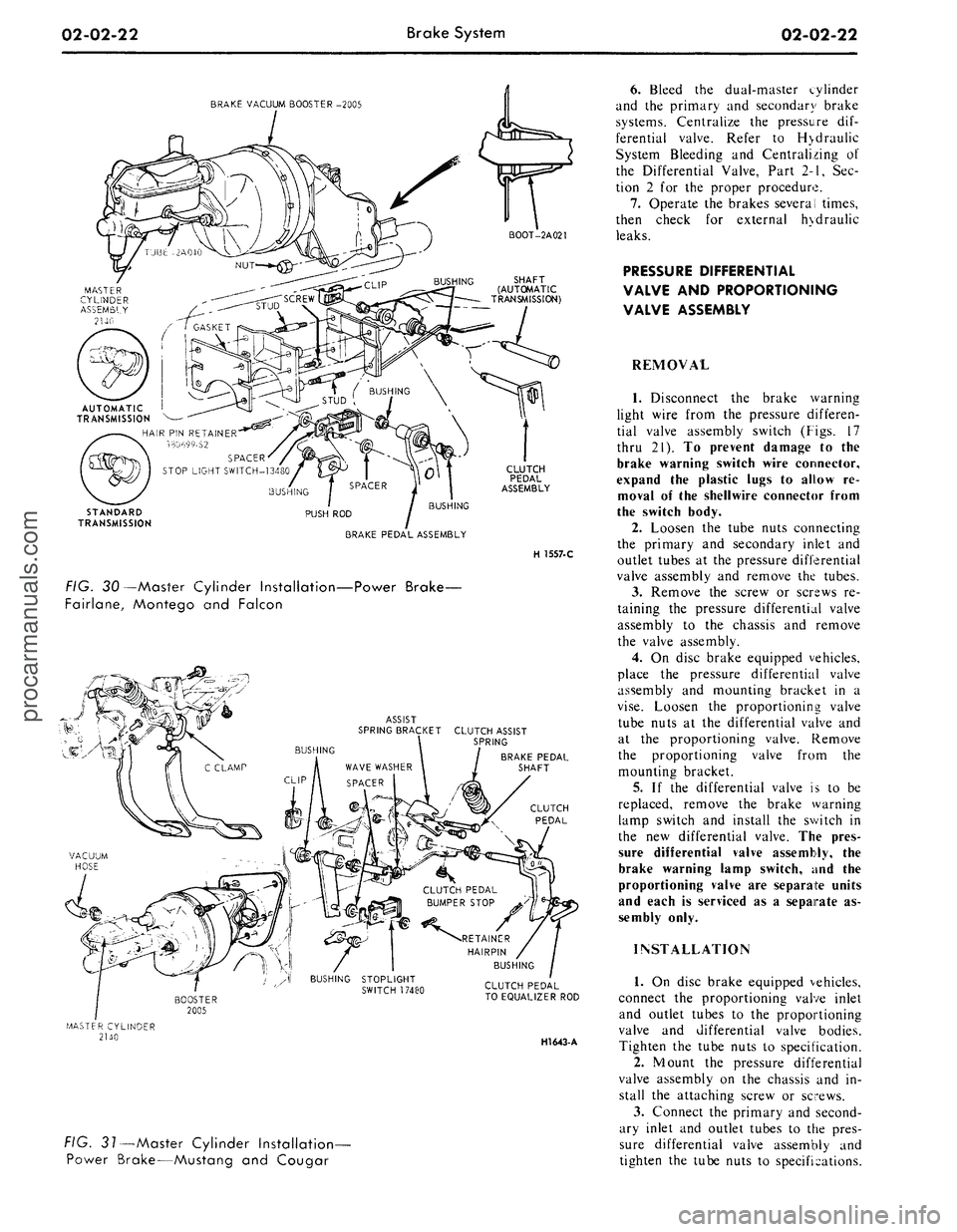
FIG. 30—Master Cylinder Installation—Power Brake-
Fairlane, Montego and Falcon
ASSIST
SPRING BRACKET CLUTCH ASSIST
\ SPRING
BRAKE PEDAL
SHAFT
CLUTCH
PEDAL
CLUTCH PEDAL
TO EQUALIZER ROD
HI643-
A
FIG. 31—Master Cylinder Installation-
Power Brake—Mustang and Cougar
6. Bleed the dual-master cylinder
and the primary and secondary brake
systems. Centralize the pressure dif-
ferential valve. Refer to H>draulic
System Bleeding and Centralizing of
the Differential Valve, Part 2-1, Sec-
tion 2 for the proper procedure.
7.
Operate the brakes several times,
then check for external hydraulic
leaks.
PRESSURE DIFFERENTIAL
VALVE AND PROPORTIONING
VALVE ASSEMBLY
REMOVAL
1.
Disconnect the brake warning
light wire from the pressure differen-
tial valve assembly switch (Figs. 17
thru 21). To prevent damage to the
brake warning switch wire connector,
expand the plastic lugs to allow re-
moval of the shellwire connector from
the switch body.
2.
Loosen the tube nuts connecting
the primary and secondary inlet and
outlet tubes at the pressure differential
valve assembly and remove the tubes.
3.
Remove the screw or screws re-
taining the pressure differential valve
assembly to the chassis and remove
the valve assembly.
4.
On disc brake equipped vehicles,
place the pressure differential valve
assembly and mounting bracket in a
vise.
Loosen the proportioning valve
tube nuts at the differential valve and
at the proportioning valve. Remove
the proportioning valve from the
mounting bracket.
5.
If the differential valve is to be
replaced, remove the brake warning
lamp switch and install the switch in
the new differential valve. The pres-
sure differential valve assembly, the
brake warning lamp switch, and the
proportioning valve are separate units
and each is serviced as a separate as-
sembly only.
INSTALLATION
1.
On disc brake equipped vehicles,
connect the proportioning valve inlet
and outlet tubes to the proportioning
valve and differential valve bodies.
Tighten the tube nuts to specification.
2.
Mount the pressure differential
valve assembly on the chassis and in-
stall the attaching screw or screws.
3.
Connect the primary and second-
ary inlet and outlet tubes to the pres-
sure differential valve assembly and
tighten the tube nuts to specifications.procarmanuals.com
Page 42 of 413
02-02-23
Brake System
02-02-23
BOOSTER ASSEMBLY- 2005
NUT-34444-S7
HOSE 2A047
MASTER CYLINDER
IDENTIFICATION
BRAKE TUBE-2263
BRAKE TUBE -2264
PRESSURE DIFFERENTIAL
VALVE ASSEMBLY-2B257
BRAKE TUBE-2B255
H 15S3-B
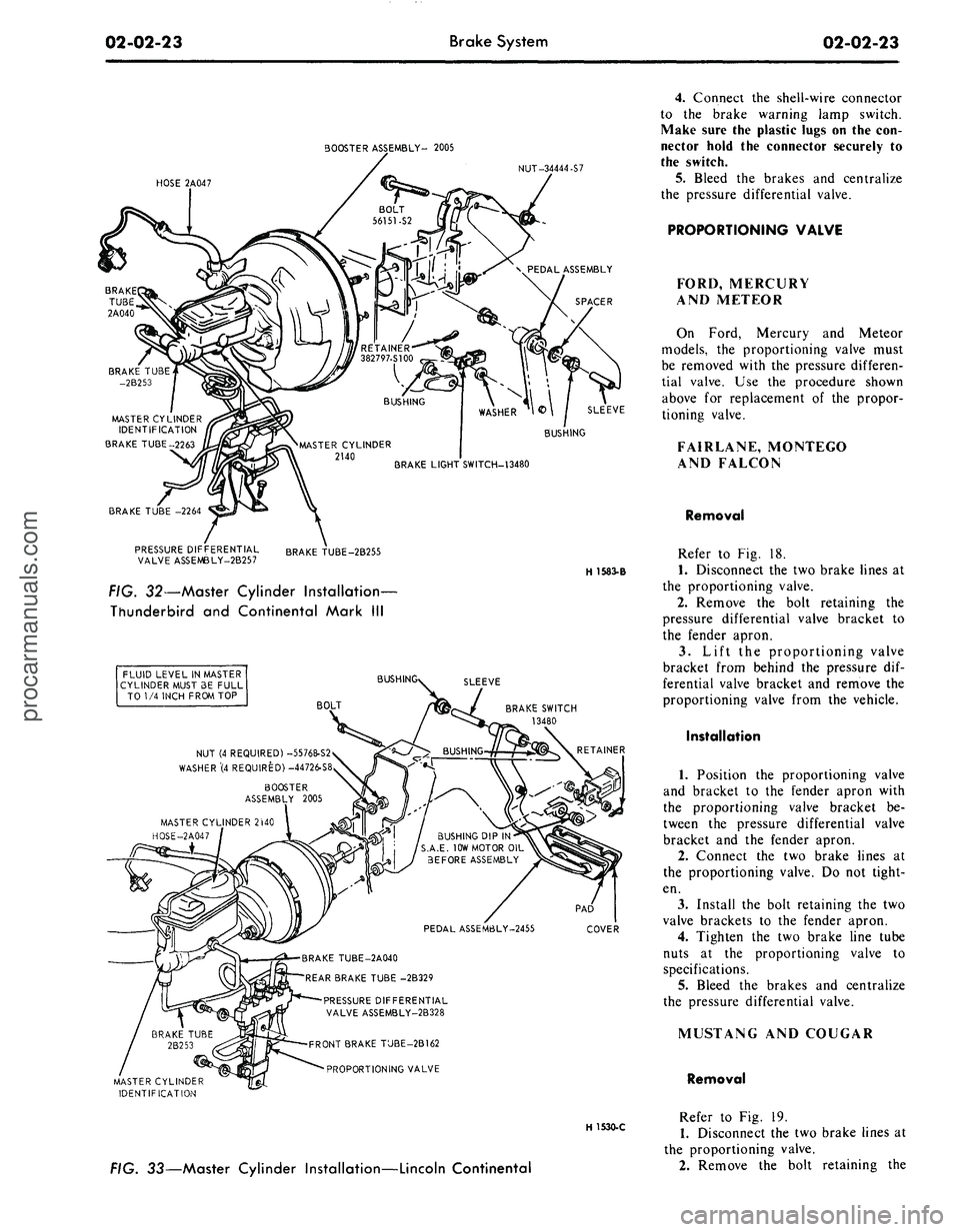
FIG. 32—Master Cylinder Installation-
Thunderbird and Continental Mark III
FLUID LEVEL IN MASTER
CYLINDER MUST 3E FULL
TO 1/4 INCH FROM TOP
BUSH
SLEEVE
BOLT
BRAKE SWITCH
13480
NUT (4 REQUIRED) -55768-S2
WASHER"(4 REQUIRED) -44726-S8
BOOSTER
ASSEMBLY 2005
MASTER CYLINDER 2WO
HOSE-2A047
BUSHING DIP IN
S.A.E. 10W MOTOR OIL
BEFORE ASSEMBLY
PEDAL ASSEM6LY-2455
COVER
BRAKE TUBE-2A040
REAR BRAKE TUBE -2B329
PRESSURE DIFFERENTIAL
VALVE ASSEMBLY-2B328
FRONT BRAKE TUBE-2B162
PROPORTIONING VALVE
MASTER CYLINDER
IDENTIFICATION
H 1530-C
FIG. 33—Master Cylinder Installation—Lincoln Continental
4.
Connect the shell-wire connector
to the brake warning lamp switch.
Make sure the plastic lugs on the con-
nector hold the connector securely to
the switch.
5. Bleed the brakes and centralize
the pressure differential valve.
PROPORTIONING VALVE
FORD, MERCURY
AND METEOR
On Ford, Mercury and Meteor
models, the proportioning valve must
be removed with the pressure differen-
tial valve. Use the procedure shown
above for replacement of the propor-
tioning valve.
FAIRLANE, MONTEGO
AND FALCON
Removal
Refer to Fig. 18.
1.
Disconnect the two brake lines at
the proportioning valve.
2.
Remove the bolt retaining the
pressure differential valve bracket to
the fender apron.
3.
Lift the proportioning valve
bracket from behind the pressure dif-
ferential valve bracket and remove the
proportioning valve from the vehicle.
Installation
1.
Position the proportioning valve
and bracket to the fender apron with
the proportioning valve bracket be-
tween the pressure differential valve
bracket and the fender apron.
2.
Connect the two brake lines at
the proportioning valve. Do not tight-
en.
3.
Install the bolt retaining the two
valve brackets to the fender apron.
4.
Tighten the two brake line tube
nuts at the proportioning valve to
specifications.
5.
Bleed the brakes and centralize
the pressure differential valve.
MUSTANG AND COUGAR
Removal
Refer to Fig. 19.
1.
Disconnect the two brake lines at
the proportioning valve.
2.
Remove the bolt retaining theprocarmanuals.com
Page 43 of 413
02-02-24
Brake
System
02-02-24
proportioning valve to the fender
apron and remove the proportioning
valve.
Installation
1.
Position the proportioning valve
to the fender apron.
2.
Connect the two brake lines at
the proportioning valve. Do not tight-
en.
3.
Install the bolt retaining the pro-
portioning valve to the fender apron.
4.
Tighten the brake line tube nuts
at the proportioning valve to specifica-
tions.
5.
Bleed the brakes and centralize
pressure differential valve.
THUNDERBIRD AND
CONTINENTAL MARK III
Removal
Refer to Fig. 20.
1.
Disconnect the two hydraulic
brake lines at the master cylinder.
2.
Remove the two nuts retaining
the master cylinder to the booster and
remove the master cylinder for clear-
ance.
3.
Disconnect the two brake lines at
the proportioning valve.
4.
Remove the bolt and nut retain-
ing the proportioning valve to the
pressure differential valve bracket and
remove the proportioning valve assem-
bly.
Installation
1.
Transfer the bracket to the new
proportioning valve.
2.
Position the proportioning valve
assembly to the pressure differential
valve bracket.
3.
Connect the two brake lines to
the proportioning valve. Do not tight-
en.
4.
Install the bolt and nut retaining
the proportioning valve to the pressure
differential valve bracket.
5.
Tighten the two brake line tube
nuts at the proportioning valve to
specifications.
6. Position the master cylinder to
the booster and install the nuts retain-
ing the master cylinder to the booster.
7.
Connect the two brake lines at
the master cylinder and tighten the
tube nuts to specifications.
8. Bleed the brakes and centralize
the pressure differential valve.
LINCOLN CONTINENTAL
Removal
Refer to Fig. 21.
1.
Disconnect the two brake lines at
the proportioning valve.
2.
Loosen the bolt and nut on the
bracket retaining the proportioning
valve to the chassis.
3.
Remove the proportioning valve
from the bracket.
Installation
- 1. Position the proportioning valve
in the bracket and connect the two
brake lines. Do not tighten.
2.
Tighten the bolt and nut on the
bracket.
3.
Tighten the tube nuts on the
brake lines at the proportioning valve
to specifications.
4.
Bleed the brakes and centralize
the pressure differential valve.
PRESSURE METERING VALVE—
LINCOLN CONTINENTAL
REMOVAL
Refer to Fig. 21.
1.
Loosen the tube nuts connecting
the inlet and outlet tubes at the me-
tering valve, and remove the tubes.
2.
Remove the two screws retaining
the metering valve to the frame
crossmember, and remove the me-
tering valve. The metering valve is ser-
viced as an assembly only.
INSTALLATION
1.
Position the metering valve to
the frame crossmember, and install
the retaining screws.
2.
Connect the inlet and outlet
tubes to the metering valve, and tight-
en the tube nuts to specification.
BRAKE BOOSTER
REMOVAL
1.
Working from inside the\ vehicle
below the instrument panel, disconnect
the booster push rod from the brake
pedal assembly. To do this, proceed as
follows:
Disconnect the stop light switch
wires at the connector. Remove the
hairpin retainer. Slide the stop light
switch off from the brake pedal pin
just far enough for the switch outer
hole to clear the pin, and then remove
the switch from the pin and booster
push rod. Be careful not to damage
the switch during removal. Slide the
booster push rod and the nylon wash-
ers and bushing off the brake pedal
pin (Figs. 29 thru 33).
2.
Open the hood and remove the
master cylinder from the booster. Se-
cure it to one side without disturbing
the hydraulic lines. It is not necessary
to disconnect the brake lines, but care
should be taken that the brake lines
are not deformed. Permanent defor-
mation of brake lines can lead to tube
failure.
3.
Disconnect the manifold vacuum
hose or hoses from the booster unit.
4.
Remove the booster-to-dash
panel attaching nuts or bolts (Figs. 29
thru 33). Remove the booster and
bracket assembly from the dash panel,
sliding the push rod link out from the
engine side of the dash panel.
5.
On Fairlane, Montego, and Fal-
con models, remove the push rod link
boot from the dash panel.
INSTALLATION
1.
On Fairlane, Montego and Fal-
con models, install the push rod link
boot in the hole in the dash panel as
shown in Fig. 23. Install the four
spacers on the mounting studs.
2.
Mount the booster and bracket
assembly to the dash panel by insert-
ing the push rod or push rod link in
through the hole and boot in the dash
panel. Install the bracket-to-dash
panel attaching lock nuts or bolts
(Figs.
29 thru 33).
3.
Connect the manifold vacuum
hose or hoses to the booster.
4.
Before installing the master cyl-
inder, check the distance from the
outer end of the booster assembly
push rod to master cylinder surface.
Turn the screw in or out to obtain the
specified length. Refer to Part 2-1,
Section 2, Power Brake Master Cylin-
der Push Rod Adjustment. Install the
master cylinder and torque the attach-
ing nuts to specifications.
5.
Working from inside the vehicle
below the instrument panel, connect
the booster push rod link to the brake
pedal assembly. To do this, proceed as
follows:
Install the inner nylon washer, the
booster push rod, and the bushing on
the brake pedal pin. Position the
switch so that it straddles the push
rod with the switch slot on the pedal
pin and the switch outer hole justprocarmanuals.com
Page 45 of 413
02-02-26
Brake System
02-02-26
14.
Remove the clutch pedal assist
spring.
15.
On non-power brakes, remove
the retainer clip from the clutch and
brake pedal shaft, then remove the
clutch pedal and shaft assembly, the
brake pedal assembly, and the bush-
ings from the pedal support bracket.
On power brakes, remove the retainer
nut from the brake pedal shaft then
remove the pedal shaft, the brake
pedal assembly and the bushings from
the pedal support bracket.
Installation
1. Apply a coating of SAE 10 en-
gine oil to the bushings and locate all
bushings in their proper places on the
clutch and brake pedal assemblies.
2.
On non-power brakes, position
the brake pedal to the pedal support
bracket, then install the clutch pedal
and shaft assembly through the sup-
port bracket and brake pedal assem-
bly. On power brakes position the
brake pedal to the pedal support
bracket, then install the pedal shaft
and nut.
3.
Install the clutch pedal assist
spring and pivot the clutch pedal
against its bumper stop. Secure the
pedal to the stop with a small C-
clamp as shown in Figs. 28 and 31.
4.
Position the pedal support
bracket assembly to the dash panel,
and to the steering column retainer
studs.
5.
Align the pedal support bracket
holes with the holes in the dash panel
and install the two attaching sheet
metal screws. On power brakes install
the nuts on the brake booster studs.
6. Install the two cap screws at-
taching the pedal support bracket to
the upper cowl bracket.
7. Install the cap screw attaching
the pedal support bracket to the top
inner cowl bracket (Figs. 28 and 31).
8. Install the inner nylon washer,
the master cylinder push rod, and the
bushing on the brake pedal pin. Posi-
tion the stop light switch so that it
straddles the push rod with the switch
slot on the pedal pin and the switch
outer hole just clearing the pin. Slide
the switch completely onto the pin,
and install the outer nylon washer as
shown in Figs. 28 and 31. Secure
these parts to the pin with the
self-
locking retainer.
9. Connect the stop light switch
wires to the connector.
10.
Connect the clutch pedal-
to-equalizer rod to the clutch pedal
assembly with the bushing and the
spring clip retainer. Apply SAE 10
engine oil to the bushing. Remove the
C-clamp from the clutch pedal.
11.
Working from the engine side
of the dash panel, on non-power
brakes, install the two cap screws at-
taching the pedal support bracket to
the dash panel. Then install the two
screws attaching the master cylinder
to the dash panel. On power brakes
install the cap screws retaining the
brake booster to the dash panel.
12.
Install the steering column.
Refer to Part 3-4, Section 2 for pro-
cedure.
13.
Adjust the clutch pedal free
play (Group 5) to specification, if re-
quired.
14.
Check the Brake Pedal Free
Height and Travel Measurements
(Part 2-1, Section 1).
15.
Connect the ground cable to the
battery.
FAIRLANE, MONTEGO,
FALCON, MUSTANG
AND COUGAR-
AUTOMATIC TRANSMISSION
Removal
1. Disconnect the stop light switch
wires at the connector.
2.
Remove the self-locking pin and
slide the stop light switch off the
brake pedal pin just far enough for
the switch outer hole to clear the pin.
Then lower the switch away from the
pin. Slide the master cylinder or
booster push rod and the nylon wash-
ers and bushing off from the brake
pedal pin (Figs. 27, 28, 30 and 31).
3.
On all vehicles except Mustang
and Cougar with power brakes, re-
move the self-locking pin and washer
from the brake pedal shaft, then re-
move the shaft, the brake pedal as-
sembly and the bushings from the
pedal support bracket. On Mustang
and Cougar vehicles with power
brakes, remove the locknut and bolt
from the pedal. Remove the pedal as-
sembly from the support bracket (Fig.
3).
Installation
1. Apply a coating of SAE 10 en-
gine oil to the bushings and locate all
the bushings in their proper places on
the pedal assembly and pedal support
bracket (Figs. 27, 28, 30 and 31).
2.
Position the brake pedal assem-
bly to the support bracket, then install
the pedal shaft or bolt through the
support bracket and brake pedal as-
sembly. Install the retainer or locknut.
3.
Install the inner nylon washer,
the master cylinder or booster push
rod, and the bushing on the brake
pedal pin. Position the switch so that
it straddles the push rod with the
switch slot on the pedal pin, and the
switch outer hole just clearing the pin.
Slide the switch completely onto the
pin, and install the outer nylon washer
as shown in Figs. 27, 28, 30 and 31.
Secure these parts to the pin with the
self-locking pin.
4.
Connect the stop light switch
wires to the connector, and install the
wires in the retaining clip.
Check the Brake Pedal Free Height
and Travel Measurements, Part 2,
Section 1.
THUNDERBIRD
AND
CONTINENTAL MARK
III
Removal
1.
Loosen the booster mounting
nuts.
2.
Disconnect the stop light switch
wires at the connector.
3.
Remove the hairpin retainer.
Slide the stop light switch off from
the brake pedal pin just far enough
for
the
switch outer hole
to
clear
the
pin,
and then lift the switch straight
upward from the pin. Slide the master
cylinder push rod and the nylon wash-
ers and bushing off from the brake
pedal pin (Fig. 32).
4.
Remove the pivot bolt and nut
that holds the pedal to the pedal sup-
port bracket. Remove the brake pedal
assembly from the pedal support
bracket, and remove the bushings.
Installation
1. Apply a coating of SAE 10 en-
gine oil to the bushings and locate all
the bushings in their proper places on
the pedal assembly (Fig. 32).
2.
Install the brake pedal assembly
and bushings to the support bracket,
and then install the pivot bolt through
the support bracket and brake pedal
assembly. Install the pivot bolt nut
and torque to specifications.
3.
Install the inner nylon washer,
the master cylinder push rod, and the
bushing on the brake pedal pin. Posi-
tion the switch so that it straddles the
push rod with the switch slot on the
pedal pin and the switch outer hole
just clearing the pin. Slide the switch
completely onto the pin, install the
outer nylon washer as shown in Fig.
32.
Secure these parts to the pin with
the hairpin retainer.procarmanuals.com
Page 46 of 413
02-02-27
Brake System
02-02-27
4.
Connect the stop light switch
wires to the connector, and install the
wires in the retaining clip.
5.
Torque the booster mounting
nuts to specifications.
LINCOLN CONTINENTAL
Removal
1.
Disconnect the battery ground
cable from the battery.
2.
It is necessary to obtain clear-
ance to remove vacuum hoses and the
electrical connector to the temperature
heat control box. Remove the two
screws retaining the relay to the fend-
er and push the relay aside. Discon-
nect the vacuum hoses and connector
at the heat control box.
3.
Working under the instrument
panel, disconnect the vacuum hoses,
wires and retaining clip from the tem-
perature heat control box. Remove the
two screws securing the temperature
control box to the dash panel.
4.
Remove the lower control hous-
ing retaining screws (6). Disconnect
the wire harnesses at the lower control
panel and place the panel aside. Re-
move the wire harness shield. Remove
the wire harness clip. Position the
wire harness aside. Remove the tem-
perature control box and position it
aside.
5.
Remove the hair-pin type retain-
er. Slide the stop light switch off the
brake pedal pin just far enough for
the switch outer hole to clear the pin.
Lift the switch upward from the pin.
Slide the master cylinder push rod,
nylon washers and bushing off the
brake pedal pin.
6. Remove the pivot bolt and nut
that holds the pedal to the pedal sup-
port bracket. Remove the brake pedal
assembly from the support bracket
and remove the bushings.
7.
If required, remove the brake
pedal pad retaining nuts and remove
the brake pedal pad.
Installation
1.
If the brake pedal pad was re-
moved, position the pad on the pedal.
Install the pad retaining nuts and tor-
que them to specification.
2.
Apply SAE 10 engine oil to the
bushings and locate all the bushings in
their proper places on the pedal as-
sembly.
3.
Install the brake pedal assembly
and bushings to the support bracket,
and then install the pivot bolt through
the support bracket and pedal assem-
bly. Install the pivot bolt nut and tor-
que it to specification.
4.
Install the inner nylon washer,the
master cylinder push rod link, and the
bushing on the brake pedal pin. Posi-
tion the switch so that it straddles the
push rod link with the switch slot on
the pedal and the switch outer hole
just clearing the pin. Install the outer
nylon washer as shown in Fig. 33. In-
stall the hair-pin type retainer on the
brake pedal pin.
5.
Connect the stop light switch
wires to the connector, and install the
wires in the retaining clip.
6. Position the wire harness and
clip on the temperature control box
and install the retaining screw. Posi-
tion the temperature control box to
the dash panel and install the two re-
taining bolts.
7.
Connect the vacuum lines and
the electrical connector to the control
box. Position the wire harness to the
control box and install the retaining
clip.
8. Position the wire harness shield
and install two retaining bolts.
9. Connect the wire harnesses to
the lower control panel and install the
retaining screws.
10.
Working within the engine
compartment, connect the wire con-
nector to the temperature heat control
box.
11.
Position the relay to the fender
apron and install the retaining bolts.
12.
Connect the ground cable to the
battery.
13.
Check the brakes and light
switch for proper operation. Close the
hood.
PARKING BRAKE CONTROL
ASSEMBLY
FORD, MERCURY
AND METEOR
Removal
Refer to Fig. 34.
1.
Make sure the parking brake is
fully released.
2.
Remove all tension from the rear
cables by backing off the adjusting nut
from the equalizer.
3.
Remove the roll pin that secures
the release knob to the cable and re-
move the knob.
4.
Remove the nut that secures the
release cable to the instrument panel
and remove the cable from the rear of
the instrument panel.
5.
Remove the two nuts attaching
the control assembly to the dash
panel.
6. Remove the cap screw attaching
the control assembly to the cowl side
bracket.
7.
Disconnect the hose to the park-
ing brake vacuum unit, if so equipped.
8. Remove the front cable assembly
retainer clip from the cable assembly
and disconnect the cable ball from the
control clevis.
9. Remove the control assembly
from the vehicle.
Installation
1.
Position the control assembly in
the vehicle.
2.
Fit the cable assembly through
its mounting hole and install the re-
taining clip. Connect the cable ball to
the control clevis.
3.
Connect the vacuum hose to the
parking brake unit, if so equipped.
4.
Install the attaching cap screw to
the cowl side bracket. Do not tighten.
5.
Install the two control assemb-
ly-to-dash panel nuts. Tighten the nuts
and the cap screw to specifications.
6. Insert the release cable into the
instrument panel and install the re-
taining nut.
7.
Install the release knob on the
cable with the roll pin.
8. Check the operation of the park-
ing brake. Adjust the parking brake
as required.
FAIRLANE, MONTEGO
AND FALCON
Removal
Refer to Fig. 35.
1.
Make sure the parking brake is
completely released.
2.
Remove all tension from the rear
cables by backing off the jam nut and
adjusting nut from the equalizer.
3.
Working inside the vehicle, re-
move the four bolts and one nut re-
taining the left air vent and cable as-
sembly to the dash and instrument
panels. Remove the vent assembly.
4.
Remove the parking brake front
cable ball retaining clip from the clev-
is.
5.
Disconnect the cable ball from
the notch in the brake clevis.
6. Remove the three screws that at-
tach the control assembly to the left
cowl inner side panel.procarmanuals.com