wheel size FORD MUSTANG 1969 Volume One Chassis
[x] Cancel search | Manufacturer: FORD, Model Year: 1969, Model line: MUSTANG, Model: FORD MUSTANG 1969Pages: 413, PDF Size: 75.81 MB
Page 19 of 413
02-01-08
Brakes
02-01-08
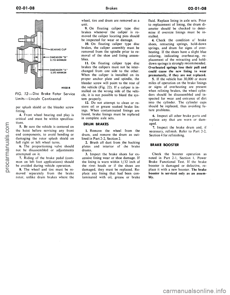
BEARING CUP
DIMENSION "B"
0.755 MINIMUM
DIMENSION "A'
0.395 MINIMUM
H1532-B
FIG. 12—Disc Brake Rotor Service
Limits—Lincoln Continental
per splash shield or the bleeder screw
fitting.
4.
Front wheel bearing end play is
critical and must be within specifica-
tions.
5.
Be sure the vehicle is centered on
the hoist before servicing any front
end components, to avoid bending or
damaging the rotor splash shield on
full right or left wheel turns.
6. The proportioning valve should
not be disassembled or adjustments
attempted on it.
7.
Riding of the brake pedal (com-
mon on left foot applications) should
be avoided during vehicle operation.
8. The wheel and tire must be re-
moved ' separately from the brake
rotor, unlike drum brakes where the
wheel, tire and drum are removed as a
unit.
9. On floating caliper type disc
brakes whenever the caliper is re-
moved the caliper locating pins should
be inspected for wear or damage.
10.
On floating caliper type disc
brakes, the caliper assembly must be
removed from the spindle prior to re-
moval of the shoe and lining assem-
blies.
11.
On floating caliper type disc
brakes the calipers must not be inter-
changed from one side to the other.
When the caliper is installed on its
proper anchor plate and spindle, the
bleeder screw will point to the rear of
the vehicle (Fig. 22). If a caliper is in-
stalled on the wrong side of the vehi-
cle,
it is not possible to bleed the sys-
tem properly.
12.
Do not attempt to clean or re-
store oil or grease soaked brake lin-
ings.
When contaminated linings are
found, brake linings must be replaced
in complete axle sets.
DRUM BRAKES
1.
Remove the wheel from the
drum, and remove the drum as out-
lined in Part 2-2, Section 2.
2.
Brush all dust from the backing
plates and interior of the brake
drums.
3.
Inspect the brake shoes for ex-
cessive lining wear or shoe damage. If
the lining is worn within 1/32 inch of
the rivet heads or if the shoes are
damaged, they must be replaced. Re-
place any lining that had been con-
taminated with oil, grease or brake
fluid. Replace lining in axle sets. Prior
to replacement of lining, the drum di-
ameter should be checked to deter-
mine if oversize linings must be in-
stalled.
4.
Check the condition of brake
shoes,
retracting springs, hold-down
springs, and drum for signs of over-
heating. If the shoes have a slight blue
coloring, indicating overheating, re-
placement of the retracting and hold-.
down springs is strongly recommended.
Overheated springs lose their pull and
could cause the new lining i:o wear
prematurely, if they are not replaced.
5. If the vehicle has 30,000 or more
miles of operation on the brake linings
or signs of overheating are present
when relining brakes, the wheel cylin-
ders should be disassembled and in-
spected for wear and entrance of dirt
into the cylinder. The cylinder cups
should be replaced, thus avoiding fu-
ture problems.
6. Inspect all other brake parts and
replace any that are worn or dam-
aged.
7.
Inspect the brake drum and, if
necessary, refinish. Refer to Part 2-2,
Section 4 for refinishing.
BRAKE BOOSTER
Check the booster operation as
noted in Part 2-1, Section 1, Power
Brake Functional Test. If the brake
booster is damaged or defective, re-
place it with a new booster. The brake
booster is serviced only as an assem-
bly.procarmanuals.com
Page 27 of 413
02-02-08
Brake System
02-02-08
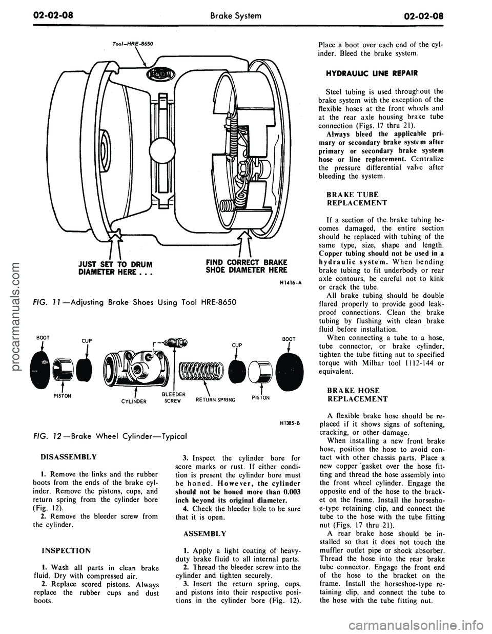
Tool-HRE-8650
JUST SET TO DRUM
DIAMETER HERE . . .
FIND CORRECT BRAKE
SHOE DIAMETER HERE
H1416-A
FIG.
7
7—Adjusting Brake Shoes Using Tool HRE-8650
BOOT
BOOT
PISTON
. BLEEDER .
CYLINDER
SCREW RETURN SPRING PIST0N
H1385-B
FIG. 72—Brake Wheel Cylinder—Typical
DISASSEMBLY
1.
Remove the links and the rubber
boots from the ends of the brake cyl-
inder. Remove the pistons, cups, and
return spring from the cylinder bore
(Fig. 12).
2.
Remove the bleeder screw from
the cylinder.
INSPECTION
1.
Wash all parts in clean brake
fluid. Dry with compressed air.
2.
Replace scored pistons. Always
replace the rubber cups and dust
boots.
3.
Inspect the cylinder bore for
score marks or rust. If either condi-
tion is present the cylinder bore must
be honed. However, the cylinder
should not be honed more than 0.003
inch beyond its original diameter.
4.
Check the bleeder hole to be sure
that it is open.
ASSEMBLY
1.
Apply a light coating of heavy-
duty brake fluip! to all internal parts.
2.
Thread the bleeder screw into the
cylinder and tighten securely.
3.
Insert the return spring, cups,
and pistons into their respective posi-
tions in the cylinder bore (Fig. 12).
Place a boot over each end of the cyl-
inder. Bleed the brake system.
HYDRAULIC LINE REPAIR
Steel tubing is used throughout the
brake system with the exception of the
flexible hoses at the front wheels and
at the fear axle housing brake tube
connection (Figs. 17 thru 21).
Always bleed the applicable pri-
mary or secondary brake system after
primary or secondary brake system
hose or line replacement. Centralize
the pressure differential valve after
bleeding the system.
BRAKE TUBE
REPLACEMENT
If a section of the brake tubing be-
comes damaged, the entire section
should be replaced with tubing of the
same type, size, shape and length.
Copper tubing should not be used in a
hydraulic system. When bending
brake tubing to fit underbody or rear
axle contours, be careful not to kink
or crack the tube.
All brake tubing should be double
flared properly to provide good leak-
proof connections. Clean the brake
tubing by flushing with clean brake
fluid before installation.
When connecting a tube to a hose,
tube connector, or brake cylinder,
tighten the tube fitting nut to specified
torque with Milbar tool 1112-144 or
equivalent.
BRAKE HOSE
REPLACEMENT
A flexible brake hose should be re-
placed if it shows signs of softening,
cracking, or other damage.
When installing a new front brake
hose,
position the hose to avoid con-
tact with other chassis parts. Place a
new copper gasket over the hose fit-
ting and thread the hose assembly into
the front wheel cylinder. Engage the
opposite end of the hose to the brack-
et on the frame. Install the horsesho-
e-type retaining clip, and connect the
tube to the hose with the tube fitting
nut (Figs. 17 thru 21).
A rear brake hose should be in-
stalled so that it does not touch the
muffler outlet pipe or shock absorber.
Thread the hose into the rear brake
tube connector. Engage the front end
of the hose to the bracket on the
frame. Install the horseshoe-type re-
taining clip, and connect the tube to
the hose with the tube fitting nut.procarmanuals.com
Page 58 of 413
02-02-39
Brake System
02-02-39
MAJOR REPAIR OPERATIONS
BRAKE DRUM REFINISHING
Minor scores on a brake drum can
be removed with sandpaper. A drum
that is excessively scored or shows a
total indicator runout of over 0.007
inch should be turned down. Remove
only enough stock to eliminate the
scores and true up the drum. The refi-
nished diameter must not exceed 0.060
inch oversize.
Check the inside diameter of the
brake drum with a brake drum mi-
crometer (Tool FRE-14^1).
If the drum diameter is less than
0.030 inch oversize after refinishing^
standard lining may be installed. If
the drum diameter is 0.030—0.060
inch oversize after refinishing, oversize
lining must be installed.
After a drum is turned down, wipe
the refinished surface with a cloth
soaked in clean denatured alcohol. If
one drum is turned down, the opposite
drum on the same axle should also be
cut down to the same size.
ROTOR REFINISHING
Rotunda Disc Brake Attachment,
FRE-2249-2, is the only recommended
tool to refinish the disc brake rotors.
The step-by-step resurfacing procedure
provided with the tool must be ad-
hered to.
The finished braking surfaces of the
rotor must be flat and parallel within
0.0007 inch; lateral runout must not
exceed 0.003 inch total indicator read-
ing, and the surface finish of the brak-
ing surfaces are to be 80/15 micro
inches. The minimum limiting dimen-
sions (Figs. 11 and 12, Part 2-1) from
the inboard bearing cup to the out-
board rotor face and from the inboard
bearing cup to the inboard rotor face
must be observed when removing ma-
terial from the rotor braking surfaces.
On all models except Lincoln Con-
tinental, the limiting dimensions are to
be measured with a ball and gage bar
(Rotunda Kit FRE-70160).
BRAKE SHOE RELINING
Brake linings that are worn to with-
in 1/32 inch of the rivet head or are
less than 0.030 inch thick (bonded lin-
ing) or have been contaminated with
brake fluid, grease or oil must be re-
placed. Failure to replace worn linings
will result in a scored drum. When it
is necessary to replace linings, they
must also be replaced on the wheel on
the opposite side of the vehicle.
Inspect brake shoes for distortion,
cracks, or looseness. If this condition
exists,
the shoe must be discarded. Do
not attempt to repair a defective brake
shoe.
1.
Wash the brake shoes thoroughly
in a clean solvent. Remove all burrs
or rough spots from the shoes.
2.
Check the inside diameter of the
brake drum with a brake drum mi-
crometer (tool FRE-1431). If the di-
ameter is less than 0.030 inches over-
size,
standard lining may be installed.
If the diameter is 0.030—0.060 inches
oversize, oversize lining should be in-
stalled.
3.
Position the new lining on the
shoe.
Starting in the center, insert and
secure the rivets, working alternately
towards each end. Replacement lin-
ings are ground and no further grind-
ing is required.
4.
Check the clearance between the
shoe and lining. The lining must seat
tightly against the shoe with not more
than 0.008 inch clearance between any
two rivets.
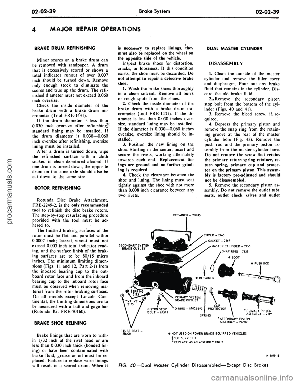
RETAINER - 2B245
DUAL MASTER CYLINDER
DISASSEMBLY
1.
Clean the outside of the master
cylinder and remove the filler cover
and diaphragm. Pour out any brake
fluid that remains in the cylinder. Dis-
card the old brake fluid.
2.*
Remove the secondary piston
stop bolt from the bottom of the cyl-
inder (Figs. 40 and 41).
3.
Remove the bleed screw, iL re-
quired.
4.
Depress the primary piston and
remove the snap ring from the retain-
ing groove at the rear of the master
cylinder bore (Fig. 42). Remove the
push rod and the primary piston as-
sembly from the master cylinder bore.
Do not remove the screw that retains
the primary return spring retainer, re-
turn spring, primary cup and protec-
tor on the primary piston. This assem-
bly is factory pre-adjusted and should
not be disassembled.
5.
Remove the secondary piston as-
sembly. Do not remove the outlet tube
seats,
outlet check valves and outlet
SECONDARY SYSTEM
BRAKE OUTLET
COVER -2166
GASKET-2167
MASTER CYLINDER -2155
SNAP RING -7821
BOOT
PUSH ROD
PRIMARY PISTON
ASSEMBLY - 2169
tTUBE SEAT-
2B220
* SECONDARY PISTON
ASSEMBLY - 2A502
• NOT USED ON POWER BRAKE EQUIPPED VEHICLES
fNOT SERVICED
•REPLACE AS AN ASSEMBLY ONLY
H 1499-B
FIG. 40— Dual Master Cylinder Disassembled—Except Disc Brakesprocarmanuals.com
Page 63 of 413
02-03-02
Specifications
02-03-02
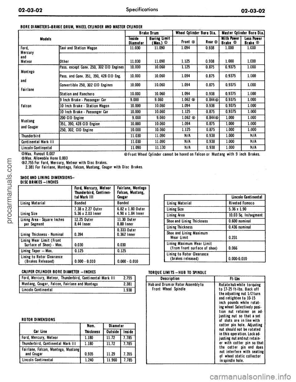
BORE DIAMETERS-BRAKE DRUM, WHEEL CYLINDER AND MASTER
Models
Ford,
Mercury
and
Meteor
Mont ego
and
Fairlane
Falcon
Mustang
and Cougar
Thunderbird
Continental Mark
III
Lincoln Continental
Taxi and Station Wagon
Other
Pass, except Conv. 250, 302 CID Engines
Pass, and Conv. 351, 390, 428 CID Eng.
Convertible 250, 302 CID Engines
Station and Ranchero
9 Inch Brake
-
Passenger Car
10 Inch Brake
•
Station Wagon
10 Inch Brake
•
Passenger Car
200 CID Engine
351,
390, 428 CID Engine
250,
302, CID Engine
CYLINDER
Brake Drum
Inside
Diameter
11.030
11.030
10.000
10.000
10.000
10.000
9.000
10.000
10.000
9.000
10.000
10.000
11.030
11.030
11.090
Boring Umit
(Max.)
®
11.090
11.090
10.060
10.060
10.060
10.060
9.060
10.060
10.060
9.060
10.060
10.060
11.090
11.090
11.130
Wheel Cylinder Bore Dia.
Front
0
1.094
L_ U25
1.125
1.094
1.094
1.094
1.062
0
1.094
1.125
1.062
®
1.094
1.125
N/A
N/A
N/A
Rear
®
0.938
0.938
0.875
0.875
0.875
0.938
0.844®
0.938
0.875
0.844®
0.875
0.875
0.938
0.938
0.938
Master Cylinder Bore Dia.
With Power
Brake
®
1.000
1.000
0.9375
0.9375
0.9375
0.9375
0.9375
0.9375
0.9375
1.000
1.000
1.000
1.000
1.000
1.000
Less Power
Brake
®
1.000
1.000
1.000
1.000
1.000
1.000
1.000
1.000
1.000
1.000
1.000
1.000
N/A
N/A
N/A
©Max. Runout
0.007
(DMax. Allowable Hone
0.003
CD2.755 For
Ford,
Mercury, Meteor with Disc Brakes.
2.381 For Fairlane, Montego, Falcon, Mustang, Cougar with Disc Brakes.
SHOE AND LINING DIMENSIONS-
DISC BRAKES-INCHES
® Front Wheel Cylinder cannot be honed on Falcon or Mustang with
9
inch Brakes.
Lining Material
Lining Size
Lining Area
-
Square Inches
per Segment
Lining Thickness • Nominal
Lining Wear Limit (Front
Surface
of
Shoe)
•
Max.
Lining Taper -Max.
Lining to Rotor Clearance
(Brakes Released)
Ford,
Mercury, Meteor
Thunderbird, Continen-
tal Mark
III
Bonded
7.38x2.27
Outer
5.36x2.03
Inner
12.25 Outer
8.44 Inner
0.394
0.030
0.125
0.000-0.010
Fairlane, Montego
Falcon,
Mustang,
Cougar
Bonded
6.82 x 1.80 Outer
4.90x1.84 Inner
11.30 Outer
8.80 Inner
0.333
Outer
0.362
Inner
0.030
0.125
0.000
• 0.010
Lining Material
Lining Size
Lining Area
Shoe and Lining Thickness
Lining Thickness
Shoe and Lining Maximum
Wear Limit
Lining Maximum Wear Limit
(from front surface
of
shoe)
Lining to Rotor Clearance
(brakes released)
Lincoln Continental
Riveted Fomoco
5.36x1.90
10.03 Sq. In/segment
0.600
nominal
0.436
nominal
0.231
0.066
0.000-0.010
CALIPER CYLINDER BORE DIAMETER -INCHES
TORQUE LIMITS-HUB TO SPINDLE
Ford,
Mercury, Meteor, Thunderbird, Continental Mark
2.755
Mustang, Cougar, Falcon, Fairlane and Montego
2.381
Lincoln Continental
1.938
ROTOR DIMENSIONS
Car Line
Ford,
Mercury, Meteor
Thunderbird, Continental Mark
III
Fairlane, Falcon, Montego, Mustang
and Cougar
Lincoln Continental
Norn.
Thickness
1.180
1.180
0.935
1.240
Diameter
Outside
11.72
11.72
11.29
11.960
Inside
7.785
7.785
7.355
7.785
Description
Hub and Drum or Rotor Assembly to
Front Wheel Spindle
Ft-Lbs
Rotate
hub
while torquing
to 17-25 ft-lbs. Backoff
the adjusting nut 1/2 turn
and retighten to 10-15
inch pounds while rotat-
ing wheel Selectively
posi-
tion
nut
retainer
on ad-
justing nut
so
that a set
of slots are in line with
cotter pin hole. Adjusting
nut should not be rotated
in this operation. Lock
ad-
justing nut and nut retain-
er with cotter pin so that
the cotter
pin end
does
not interfere with seating
of wheel static collector
in spindle hole.procarmanuals.com
Page 85 of 413
03-02-09
Suspension
03-02-09
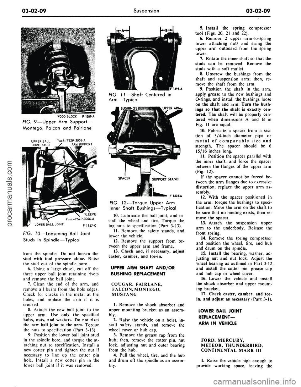
WOOD BLOCK
F
1287-A
FIG. 9—Upper
Arm
Support—
Montego, Falcon
and
Fairlane
Tool-T62F-3006-A
ARM SUPPORT
LOWER BALL JOINT
SLEEVE
Too/-T57P-3006-A
F 1157-C
FIG. TO—Loosening Ball Joint
Studs
in
Spindle—Typical
from
the
spindle.
Do not
loosen
the
stud with tool pressure alone. Raise
the stud
out of the
spindle bore.
6. Using
a
large chisel,
cut off the
three upper ball joint retaining rivets
and remove
the
ball joint.
7.
Clean
the end of the arm, and
remove
all
burrs from
the
hole edges.
Check
for
cracks
in the
metal
at the
holes,
and
replace
the arm if it is
cracked.
8. Attach
the new
ball joint
to the
upper
arm. Use
only
the
specified
bolts,
nuts,
and
washers.
Do not
rivet
the
new
ball joint
to the
arm. Torque
the nuts
to
specification (Part 3-13).
9. Position
the
lower ball joint stud
in
the
spindle bore,
and
torque
the at-
taching
nut to
specification. Install
a
new cotter
pin and
tighten
the nut if
necessary
to
line
up the
cotter
pin
hole.
Install
a new
cotter
pin in the
lower ball joint
if it was
removed.
1495-A
FIG. 11 —Shaft Centered
in
Arm—Typical
F 1494- A
FIG. 12—Torque Upper
Arm
Inner Shaft Bushings—Typical
10.
Lubricate
the
ball joint,
and in-
stall
the
wheel
and
tire. Torque
the
lug nuts
to
specification (Part 3-13).
11.
Remove
the
safety stands,
and
lower
the
vehicle.
12.
Remove
the
support from
be-
tween
the
upper
arm and
frame.
13.
Check
and, if
necessary, adjust
caster, camber,
and
toe-in.
UPPER ARM SHAFT AND/OR
BUSHING REPLACEMENT
COUGAR, FAIRLANE,
FALCON, MONTEGO,
MUSTANG
1.
Remove
the
shock absorber
and
upper mounting bracket
as an
assem-
bly.
2.
Raise
the
vehicle
on a
hoist,
in-
stall safety stands,
and
remove
the
wheel cover
or hub cap.
3.
Remove
the
grease
cap
from
the
hub;
then, remove
the
cotter
pin, nut
lock, adjusting
nut and
outer bearing
from
the hub.
4.
Pull
the
wheel, tire,
and the hub
and drum
off the
spindle
as an
assem-
bly.
5.
Install
the
spring compressor
tool (Figs.
20, 21 and 22).
6. Remove
2
upper arm-to-spring
tower attaching nuts
and
swing
the
upper
arm
outboard from
the
spring
tower.
7.
Rotate
the
inner shaft
so
that
the
studs
can be
removed. Remove
the
studs with
a
soft mallet.
8. Unscrew
the
bushings from
the
shaft
and
suspension
arm;
then,
re-
move
the
shaft from
the arm.
9. Position
the
shaft
in the. arm,
apply grease
to the new
bushings
and
O-rings,
and
install
the
bushings loose
on
the
shaft
and
arm. Turn
the
bush-
ings
so
that
the
shaft
is
exactly
cen-
tered.
The
shaft will
be
properly
cen-
tered when dimensions
A and B in
Fig.
11 are
equal.
10.
Fabricate
a
spacer from
a sec-
tion
of
3/4-inch diameter pipe
or
metal
of
comparable size
and
strength.
The
spacer should
be 6
15/16 inches long.
11.
Position
the
spacer parallel with
the inner shaft,
and
force
the
spacer
between
the
flanges
of the
upper
arm
(Fig.
12).
If
the
spacer cannot
be
forced
be-
tween
the arm
flanges due
to
excessive
distortion, replace
the
upper
arm as-
sembly.
12.
With
the
spacer positioned
in
the
arm,
torque
the
bushings
to
speci-
fication. Move
the arm on the
shaft
to
be sure that
no
binding exists, then
re-
move
the
spacer.
13.
Attach
the
suspension upper
arm
to the
underbody. Release
the
front spring.
14.
Remove
the
spring compressor
and position
the
wheel, tire,
and hub
and drum
on the
spindle.
15.
Install
the
bearing, washer,
ad-
justing
nut and nut
lock. Adjust
the
wheel bearing
as
outlined
in
Part
3-12
and install
the
cotter
pin,
grease
cap
and
hub cap or
wheel cover.
16.
Lower
the
vehicle
and
install
the shock absorber
and
upper mount-
ing bracket.
17.
Check caster, camber,
and toe-
in,
and
adjust
as
necessary (Part 3-1).
LOWER BALL JOINT
REPLACEMENT-
ARM
IN
VEHICLE
FORD, MERCURY,
METEOR, THUNDERBIRD,
CONTINENTAL MARK
III
1.
Raise
the
vehicle high enough
to
provide working space, leaving
theprocarmanuals.com
Page 142 of 413
03-07-04
Ford Design Non-Integral Power Steering System
03-07-04
12.
Stop the engine, and check the
control valve and hose connections for
fluid leaks. Correct the cause of any
leaks.
13.
Check the fluid level, and refill
the reservoir if necessary.
14.
With the engine running check
the position of the steering wheel
when the front wheels are in the
straight-ahead position.Do not make
any adjustments until toe-in is
checked.
15.
Keep the engine running, and
check toe-in. If either toe-in or steer-
ing wheel position is not correct make
all necessary adjustments (Part 3-1) at
the spindle connecting rod sleeves.
16.
Check the effort to turn the
wheels in both directions. The effort
should be about equal in both direc-
tions.
POWER CYLINDER
REMOVAL
1.
Disconnect the two fluid lines
from the power cylinder and allow
them to drain into a container.
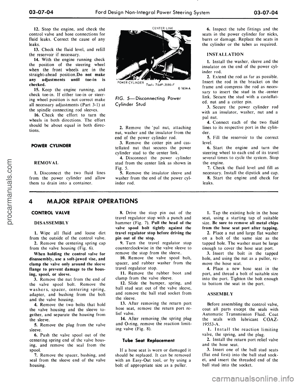
CENTER LINK
POWER CYLINDER
Tool- T64P-3590-F
G 1654-A
FIG. 5—Disconnecting Power
Cylinder Stud
2.
Remove the 'pal nut, attaching
nut, washer and the insulator from the
end of the power cylinder rod.
3.
Remove the cotter pin and cas-
tellated nut that secures the power
cylinder stud to the center link.
4.
Disconnect the power cylinder
stud from the center link as shown in
Fig. 5.
5.
Remove the insulator sleeve and
washer from the end of the power cyl-
inder rod.
6. Inspect the tube fittings and the
seats in the power cylinder for nicks,
burrs or damage. Replace the seats in
the cylinder or the tubes as required.
INSTALLATION
1.
Install the washer, sleeve and the
insulator on the end of the power cyl-
inder rod.
2.
Extend the rod as far as possible.
Insert the rod in the bracket on the
frame and compress the rod as neces-
sary to insert the stud in the -center
link. Secure the stud with a castellat-
ed, nut and a cotter pin.
3.
Secure the power cylinder rod
with an insulator, washer, nut and a
pal nut.
4.
Connect each of the two fluid
lines to its respective port in the cylin-
der.
5.
Fill the reservoir to the correct
level.
6. Start the engine and turn the
steering wheel to each end of its travel
several times to cycle the system. Stop
the engine.
7.
Check the fluid level and fill as
necessary. Install the dipstick and cap.
8. Start the engine and check for
leaks.
MAJOR REPAIR OPERATIONS
CONTROL VALVE
DISASSEMBLY
1.
Wipe all fluid and loose dirt
from the outside of the control valve.
2.
Remove the centering spring cap
from the valve housing (Fig. 6).
When holding the control valve for
disassembly, use a soft-jawed vise, and
clamp the valve only around the sleeve
flange to prevent damage to the hous-
ing, spool, or sleeve.
3.
Remove the nut from the end of
the valve spool bolt. Remove the
washers, spacer, centering spring,
adapter, and bushing from the bolt
and the valve housing.
4.
Remove the two bolts that hold
the valve housing and the sleeve to-
gether, and separate the housing from
the sleeve.
5.
Remove the plug from the valve
sleeve.
6. Push the valve spool out of the
centering spring end of the valve hous-
ing, and remove the seal from the
spool.
7.
Remove the spacer, bushing, and
seal from the sleeve end of the valve
housing.
8. Drive the stop pin out of the
travel regulator stop with a punch and
hammer (Fig. 7). Pull the head of the
valve spool bolt tightly against the
travel regulator stop before driving the
pin out of the stop.
9. Turn the travel regulator stop
counterclockwise in the valve sleeve to
remove the stop from the sleeve.
10.
Remove the valve spool bolt,
spacer, and rubber washer from the
travel regulator stop.
11.
Remove the rubber boot and
clamp from the valve sleeve.
12.
Slide the bumper, spring, and
ball stud seat out of the valve sleeve,
and remove the ball stud socket from
the sleeve.
13.
After removing the return port
hose seat, remove the return port re-
lief valve.
14.
After removing the spring plug
and O-ring, remove the reaction limit-
ing valve (Fig. 8).
Tube Seat Replacement
If a hose seat is worn or damaged it
should be replaced. It can be removed
with an Easy-Out tool, or by using a
bolt of appropriate size as a puller.
1.
Tap the existing hole in the hose
seat, using a starting tap of suitable
size.
Be sure to remove all metal chips
from the hose seat port after tapping.
2.
Place a nut and large flat washer
on a bolt of the same size as the
tapped hole. The washer must be large
enough to cover the hose seat port.
3.
Insert the bolt in the tapped
hole,
and using the nut as a puller, re-
move the hose seat.
4.
Place a new hose seat in the
port, and thread a bolt of suitable size
into the port. Tighten the bolt enough
to bottom the seat in the port.
ASSEMBLY
Before assembling the control valve,
coat all parts except the seals with
Automatic Transmission Fluid. Coat
the seals with lubricant COAZ-
19553-A.
1.
Install the reaction limiting
valve, the spring, and the plug.
2.
Install the return port relief valve
and the hose seat.
3.
Insert one of the ball stud seats
(flat end first) into the ball stud sock-
et, and insert the threaded end of the
ball stud into the socket.procarmanuals.com
Page 145 of 413
03-08-01
Ford Design Integral Power Steering Gear
03-08-01
PART
3-8
Ford Design Integral Power
Steering Gear
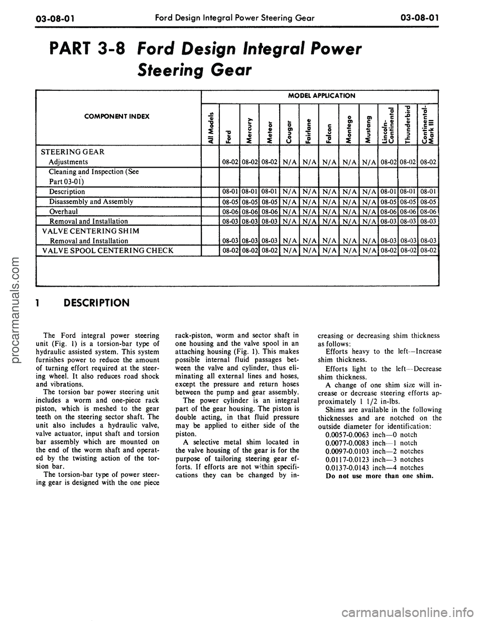
COMPONENT INDEX
STEERING GEAR
Adjustments
Cleaning
and
Inspection
(See
Part 03-01)
Description
Disassembly
and
Assembly
Overhaul
Removal
and
Installation
VALVE CENTERING SHIM
Removal
and
Installation
VALVE SPOOL CENTERING CHECK
MODEL APPLICATION
All Models
Ford
08-02
08-01
08-05
08-06
08-03
08-03
08-02
Mercury
08-02
08-01
08-05
08-06
08-03
08-03
08-02
Meteor
08-02
08-01
08-05
08-06
08-03
08-03
08-02
Cougar
N/A
N/A
N/A
N/A
N/A
N/A
N/A
Fairlane
N/A
N/A
N/A
N/A
N/A
N/A
N/A
Falcon
N/A
N/A
N/A
N/A
N/A
N/A
N/A
Montego
N/A
N/A
N/A
N/A
N/A
N/A
N/A
Mustang
N/A
N/A
N/A
N/A
N/A
N/A
N/A
Lincoln-
Continental
08-02
08-01
08-05
08-06
08-03
08-03
08-02
Thunderbird
08-02
08-01
08-05
08-06
08-03
08-03
08-02
Continental-
Mark
III
08-02
08-01
08-05
08-06
08-03
08-03
08-02
DESCRIPTION
The Ford integral power steering
unit
(Fig. 1) is a
torsion-bar type
of
hydraulic assisted system. This system
furnishes power
to
reduce
the
amount
of turning effort required
at the
steer-
ing wheel.
It
also reduces road shock
and vibrations.
The torsion
bar
power steering unit
includes
a
worm
and
one-piece rack
piston, which
is
meshed
to the
gear
teeth
on the
steering sector shaft.
The
unit also includes
a
hydraulic valve,
valve actuator, input shaft
and
torsion
bar assembly which
are
mounted
on
the
end of the
worm shaft
and
operat-
ed
by the
twisting action
of the tor-
sion
bar.
The torsion-bar type
of
power steer-
ing gear
is
designed with
the one
piece
rack-piston, worm
and
sector shaft
in
one housing
and the
valve spool
in an
attaching housing
(Fig. 1).
This makes
possible internal fluid passages
bet-
ween
the
valve
and
cylinder, thus
eli-
minating
all
external lines
and
hoses,
except
the
pressure
and
return hoses
between
the
pump
and
gear assembly.
The power cylinder
is an
integral
part
of the
gear housing.
The
piston
is
double acting,
in
that fluid pressure
may
be
applied
to
either side
of the
piston.
A selective metal shim located
in
the valve housing
of the
gear
is for the
purpose
of
tailoring steering gear
ef-
forts.
If
efforts
are not
within specifi-
cations they
can be
changed
by in-
creasing
or
decreasing shim thickness
as follows:
Efforts heavy
to the
left—Increase
shim thickness.
Efforts light
to the
left—Decrease
shim thickness.
A change
of one
shim size will
in-
crease
or
decrease steering efforts
ap-
proximately
1 1/2
in-lbs.
Shims
are
available
in the
following
thicknesses
and are
notched
on the
outside diameter
for
identification:
0.0057-0.0063 inch—0 notch
0.0077-0.0083 inch—1 notch
0.0097-0.0103 inch—2 notches
0.0117-0.0123 inch—3 notches
0.0137-0.0143 inch—4 notches
Do
not use
more than
one
shim.
procarmanuals.com
Page 199 of 413
04-02-02
Rear Axle — Removable Carrier Type
04-02-02
COMPONENT INDEX
PINION SPACER (Solid)
Determining Spacer Size
Removal and Installation
REAR WHEEL BEARINGS AND SEALS
Cleaning and Inspection
Removal and Installation
TRACTION-LOK DIFFERENTIAL
Cleaning and Inspection
Description
Disassembly and Overhaul
Removal and Installation
U-JOINT FLANGE
Cleaning and Inspection
Removal and Installation
MODEL APPLICATION
All
Models
02-18
02-18
01-10
02-04
01-10
02-07
Ford
N/A
N/A
N/A
N/A
Mercury
N/A
N/A
N/A
N/A
Meteor
N/A
N/A
N/A
JN/A
Cougar
01-10
02-03
02-22
02-13
Fairlane
01-10
02-03
02-22
02-13
Falcon
01-10
02-03
02-22
02-13
Montego
01-10
02-03
02-22
02-13
Mustang
01-10
02-03
02-22
02-13
Lincoln-
Continental
N/A
02-03
N/A
N/A
Thunderbird
N/A
N/A
N/A
N/A
Continental-
Mark
III
N/A
N/A
N/A
N/A
A page number indicates that the item is for the vehicle listed at the head of the column.
N/A indicates that the item is not applicable to the vehicle listed.
1 DESCRIPTION
CONVENTIONAL AXLE
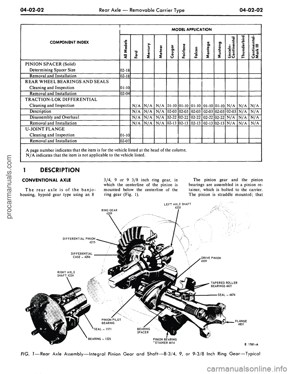
The rear axle is of the banjo-
housing, hypoid gear type using an 8
3/4, 9 or 9 3/8 inch ring gear, in
which the centerline of the pinion is
mounted below the centerline of the
ring gear (Fig. 1).
The pinion gear and the pinion
bearings are assembled in a pinion re-
tainer, which is bolted to the carrier.
The pinion is straddle mounted; that
LEFT AXLE SHAFT
4235
DRIVE PINION
4209
TAPERED ROLLER
BEARINGS 4621
SEAL - 4676
FIG.
1
—
Rear
Axle Assembly—Integral Pinion Gear and Shaft—8-3/4, 9, or 9-3/8 Inch Ring Gear—Typical
procarmanuals.com
Page 244 of 413
04-05-03
Specifications
04-05-03
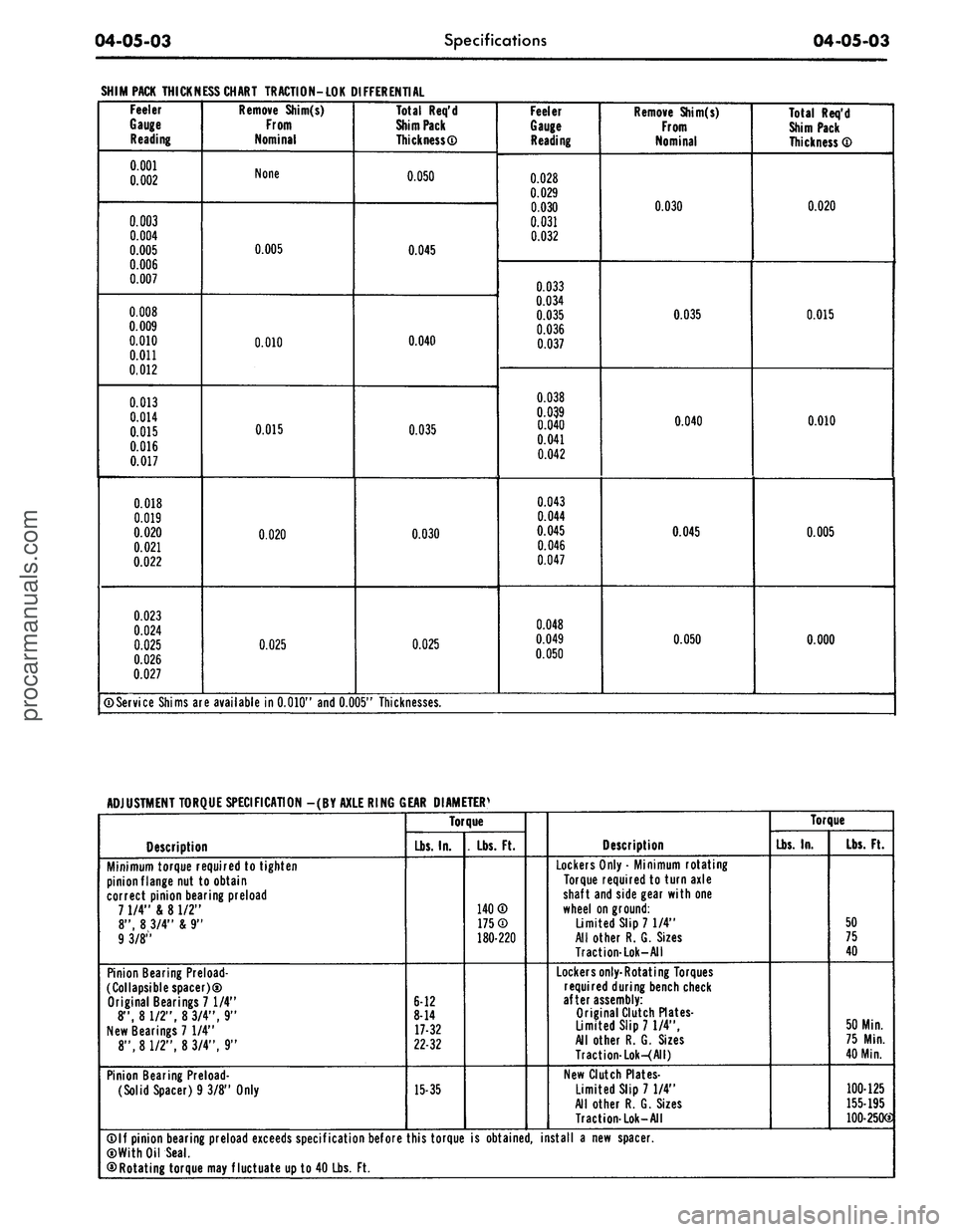
SHIM PACK THICKNESS CHART TRACTION-LOK DIFFERENTIAL
Feeler
Gauge
Reading
0.001
0.002
0.003
0.004
0.005
0.006
0.007
0.008
0.009
0.010
0.011
0.012
0.013
0.014
0.015
0.016
0.017
0.018
0.019
0.020
0.021
0.022
0.023
0.024
0.025
0.026
0.027
Remove Shim(s)
From
Nominal
None
0.005
0.010
0.015
0.020
0.025
Total Req'd
Shim Pack
Thickness®
0.050
0.045
0.040
0.035
0.030
0.025
Feeler
Gauge
Reading
0.028
0.029
0.030
0.031
0.032
0.033
0.034
0.035
0.036
0.037
0.038
0.039
0.040
0.041
0.042
0.043
0.044
0.045
0.046
0.047
0.048
0.049
0.050
Remove Shim(s)
From
Nominal
0.030
0.035
0.040
0.045
0.050
Total Req'd
Shim Pack
Thickness ®
0.020
0.015
0.010
0.005
0.000
©Service Shims are available in 0.010" and 0.005" Thicknesses.
ADJUSTMENT TORQUE SPECIFICATION -(BY AXLE RING GEAR DIAMETERS
Description
Minimum torque required to tighten
pinion flange nut to obtain
correct pinion bearing preload
7 1/4" & 8 1/2"
8", 8 3/4" & 9"
9 3/8"
Pinion Bearing Preload-
collapsible spacer)®
Original Bearings 7 1/4"
8", 8 1/2", 8 3/4", 9"
New Bearings 7 1/4"
8", 8 1/2", 8 3/4", 9"
Pinion Bearing Preload-
(Solid Spacer) 9 3/8" Only
Torque
Lbs.
In.
6-12
8-14
17-32
22-32
15-35
. Lbs. Ft.
140®
175®
180-220
Description
Lockers Only • Minimum rotating
Torque required to turn axle
shaft and side gear with one
wheel on ground:
Limited Slip 7 1/4"
All other R. G. Sizes
Traction-Lok-All
Lockers only-Rotating Torques
required during bench check
after assembly:
Original Clutch Plates-
Limited Slip 71/4",
All other R. G. Sizes
Traction-Lok-(All)
New Clutch Plates-
Limited Slip 7 1/4"
All other R. G. Sizes
Traction-Lok-All
Torque
Lbs.
In.
Lbs.
Ft.
50
75
40
50 Min.
75 Min.
40 Min.
100-125
155-195
100-250G
©If pinion bearing preload exceeds specification before this torque is obtained, install a new spacer.
©With Oil Seal.
©Rotating torque may fluctuate up to 40 Lbs. Ft.procarmanuals.com
Page 257 of 413
05-02-03
General Clutch Service
05-02-03
in the direction of the face runout
arrow and its center line is parallel to
the center line of the face runout
arrow.
18.
Determine the amount of the
face runout on the B arrow scale.
19.
The value of the circular line
beneath the amount of face runout
will be the desired reading. If the
reading is in excess of 0.014 inch the
housing alignment is unacceptable.
20.
Remove the Dia-L-lgner gauge
from the flywheel housing.
21.
Install the spark plugs and con-
nect the wires.
ENGINE IN VEHICLE
Since any change in face alignment
will change bore alignment, it may be
possible to correct bore alignment by
changing face alignment. Face align-
ment can be changed by shimming be-
tween the flywheel housing and en-
gine.
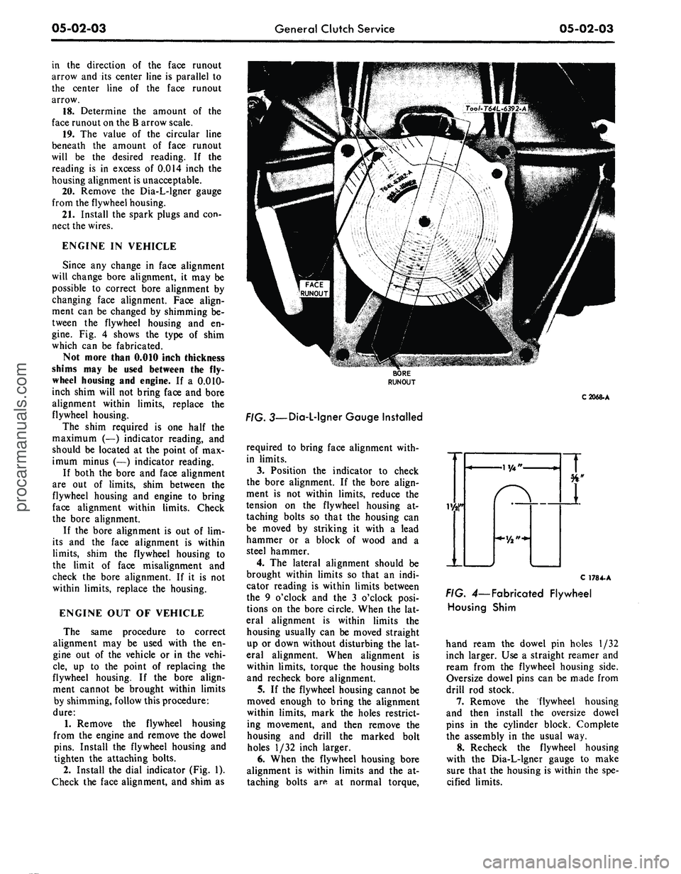
Fig. 4 shows the type of shim
which can be fabricated.
Not more than 0.010 inch thickness
shims may be used between the fly-
wheel housing and engine. If a 0.010-
inch shim will not bring face and bore
alignment within limits, replace the
flywheel housing.
The shim required is one half the
maximum (—) indicator reading, and
should be located at the point of max-
imum minus (—) indicator reading.
If both the bore and face alignment
are out of limits, shim between the
flywheel housing and engine to bring
face alignment within limits. Check
the bore alignment.
If the bore alignment is out of lim-
its and the face alignment is within
limits,
shim the flywheel housing to
the limit of face misalignment and
check the bore alignment. If it is not
within limits, replace the housing.
ENGINE OUT OF VEHICLE
The same procedure to correct
alignment may be used with the en-
gine out of the vehicle or in the vehi-
cle,
up to the point of replacing the
flywheel housing. If the bore align-
ment cannot be brought within limits
by shimming, follow this procedure:
dure:
1.
Remove the flywheel housing
from the engine and remove the dowel
pins.
Install the flywheel housing and
tighten the attaching bolts.
2.
Install the dial indicator (Fig. 1).
Check the face alignment, and shim as
C2068-A
. 3—Dia-L-lgner Gauge Installed
required to bring face alignment with-
in limits.
3.
Position the indicator to check
the bore alignment. If the bore align-
ment is not within limits, reduce the
tension on the flywheel housing at-
taching bolts so that the housing can
be moved by striking it with a lead
hammer or a block of wood and a
steel hammer.
4.
The lateral alignment should be
brought within limits so that an indi-
cator reading is within limits between
the 9 o'clock and the 3 o'clock posi-
tions on the bore circle. When the lat-
eral alignment is within limits the
housing usually can be moved straight
up or down without disturbing the lat-
eral alignment. When alignment is
within limits, torque the housing bolts
and recheck bore alignment.
5.
If the flywheel housing cannot be
moved enough to bring the alignment
within limits, mark the holes restrict-
ing movement, and then remove the
housing and drill the marked bolt
holes 1/32 inch larger.
6. When the flywheel housing bore
alignment is within limits and the at-
taching bolts are at normal torque,
C 178 4-A
FIG. 4— Fabricated Flywheel
Housing Shim
hand ream the dowel pin holes 1/32
inch larger. Use a straight reamer and
ream from the flywheel housing side.
Oversize dowel pins can be made from
drill rod stock.
7.
Remove the flywheel housing
and then install the oversize dowel
pins in the cylinder block. Complete
the assembly in the usual way.
8. Recheck the flywheel housing
with the Dia-L-lgner gauge to make
sure that the housing is within the spe-
cified limits.procarmanuals.com