FORD MUSTANG 2003 Workshop Manual
MUSTANG 2003
FORD
FORD
https://www.carmanualsonline.info/img/11/56942/w960_56942-0.png
FORD MUSTANG 2003 Workshop Manual
Page 2446 of 4378
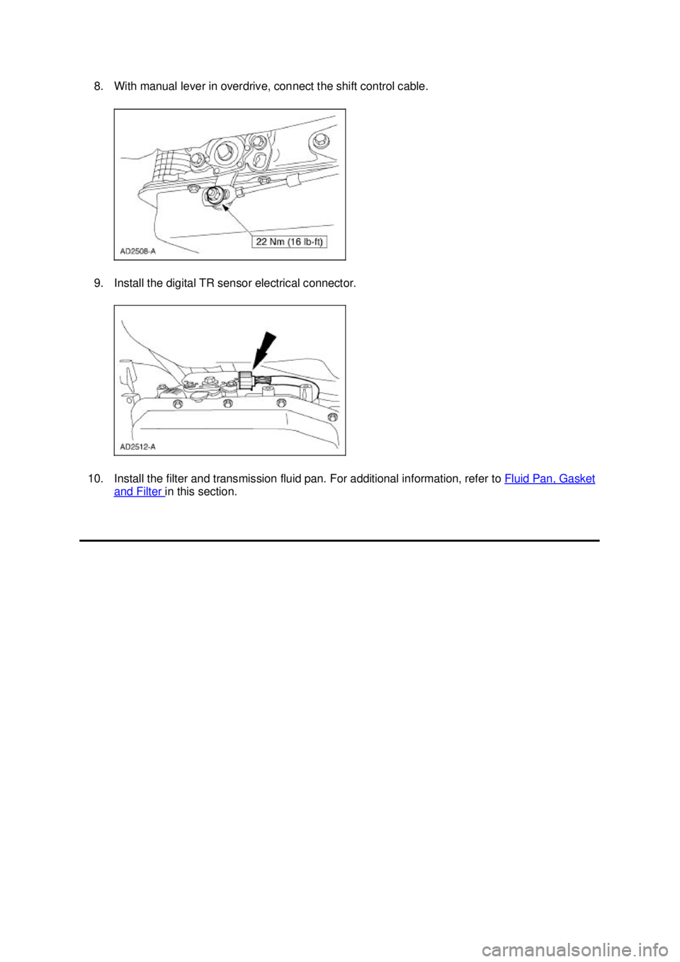
8. With manual lever in overdrive, connect the shift control cable.
9. Install the digital TR sensor electrical connector.
10. Install the filter and transmission fluid pan. For additional information, refer to Fluid Pan, Gasket and Filter in this section. �K�l�j . 6 �b�a
62003 Mustang Workshop Manual
18. 11. 2011file:///C:/Ford/2000 - 2004/tsocache/SHEF_2748/S3B~us~en~ ...
Page 2447 of 4378
IN-
VEHICLE REPAIR
Digital Transmission Range (TR) Sensor
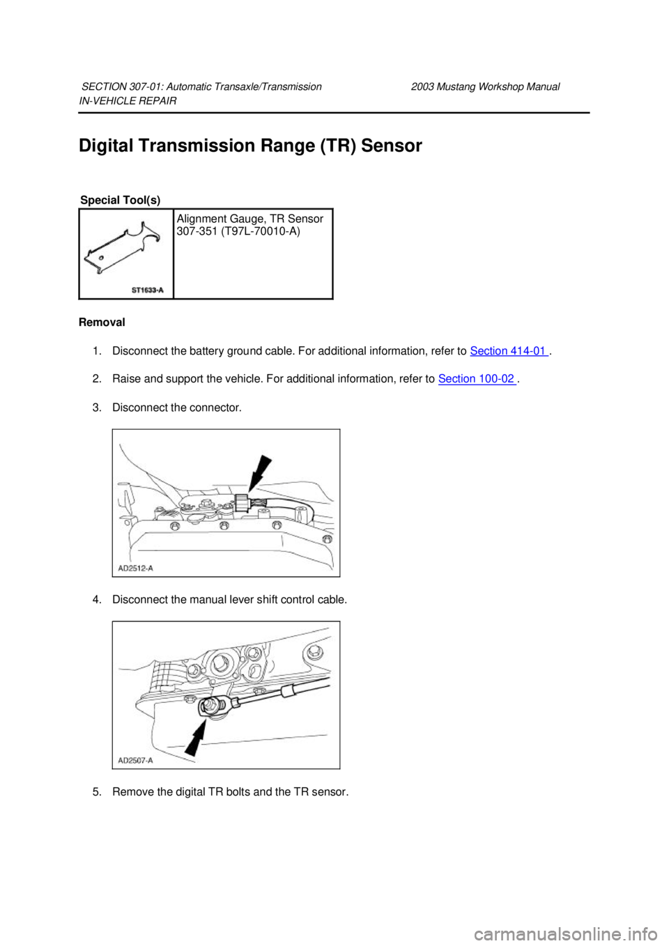
Removal 1. Disconnect the battery ground cable. For additional information, refer to Section 414 - 01 .
2. Raise and support the vehicle. For additional information, refer to Section 100 - 02 .
3. Disconnect the connector.
4. Disconnect the manual lever shift control cable.
5. Remove the digital TR bolts and the TR sensor.
SECTION 307-
01: Automatic Transaxle/Transmission 2003 Mustang Workshop Manual Special Tool(s)
Alignment Gauge, TR Sensor
307-
351 (T97L-70010- A) �K�l�j . 1 �b�a
42003 Mustang Workshop Manual
18. 11. 2011file:///C:/Ford/2000 - 2004/tsocache/SHEF_2748/S3B~us~en~ ...
Page 2448 of 4378
Installation
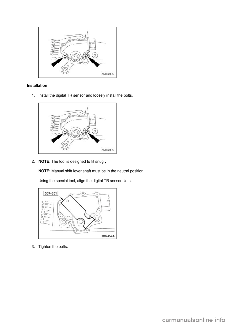
1. Install the digital TR sensor and loosely install the bolts.
2. NOTE: The tool is designed to fit snugly.
NOTE: Manual shift lever shaft must be in the neutral position.
Using the special tool, align the digital TR sensor slots.
3. Tighten the bolts. �K�l�j . 2 �b�a
42003 Mustang Workshop Manual
18. 11. 2011file:///C:/Ford/2000 - 2004/tsocache/SHEF_2748/S3B~us~en~ ...
Page 2449 of 4378
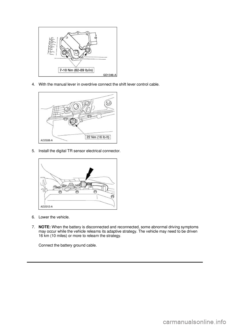
4. With the manual lever in overdrive connect the shift lever control cable.
5. Install the digital TR sensor electrical connector.
6. Lower the vehicle.
7.
NOTE: When the battery is disconnected and reconnected, some abnormal driving symptoms
may occur while the vehicle relearns its adaptive strategy. The vehicle may need to be driven
16 km (10 miles) or more to relearn the strategy.
Connect the battery ground cable. �K�l�j . 3 �b�a
42003 Mustang Workshop Manual
18. 11. 2011file:///C:/Ford/2000 - 2004/tsocache/SHEF_2748/S3B~us~en~ ...
Page 2462 of 4378
IN-
VEHICLE REPAIR
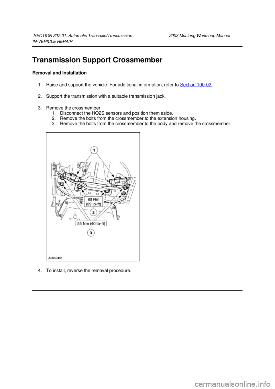
Transmission Support Crossmember
Removal and Installation 1. Raise and support the vehicle. For additional information, refer to Section 100 - 02 .
2. Support the transmission with a suitable transmission jack.
3. Remove the crossmember. 1. Disconnect the HO2S sensors and position them aside.
2. Remove the bolts from the crossmember to the extension housing.
3. Remove the bolts from the crossmember to the body and remove the crossmember.
4. To install, reverse the removal procedure.
SECTION 307-
01: Automatic Transaxle/Transmission 2003 Mustang Workshop Manual �K�l�j . 1 �b�a
22003 Mustang Workshop Manual
18. 11. 2011file:///C:/Ford/2000 - 2004/tsocache/SHEF_2748/S3B~us~en~ ...
Page 2474 of 4378
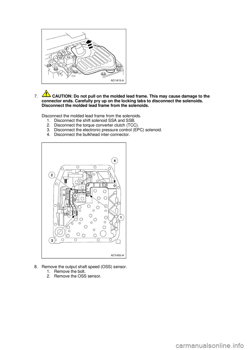
7.
CAUTION: Do not pull on the molded lead frame. This may cause damage to the
connector ends. Carefully pry up on the locking tabs to disconnect the solenoids.
Disconnect the molded lead frame from the solenoids.
Disconnect the molded lead frame from the solenoids. 1. Disconnect the shift solenoid SSA and SSB.
2. Disconnect the torque converter clutch (TCC).
3. Disconnect the electronic pressure control (EPC) solenoid.
4. Disconnect the bulkhead inter- connector.
8. Remove the output shaft speed (OSS) sensor. 1. Remove the bolt.
2. Remove the OSS sensor. �K�l�j . 4 �b�a
162003 Mustang Workshop Manual
18. 11. 2011file:///C:/Ford/2000 - 2004/tsocache/SHEF_2748/S3B~us~en~ ...
Page 2475 of 4378
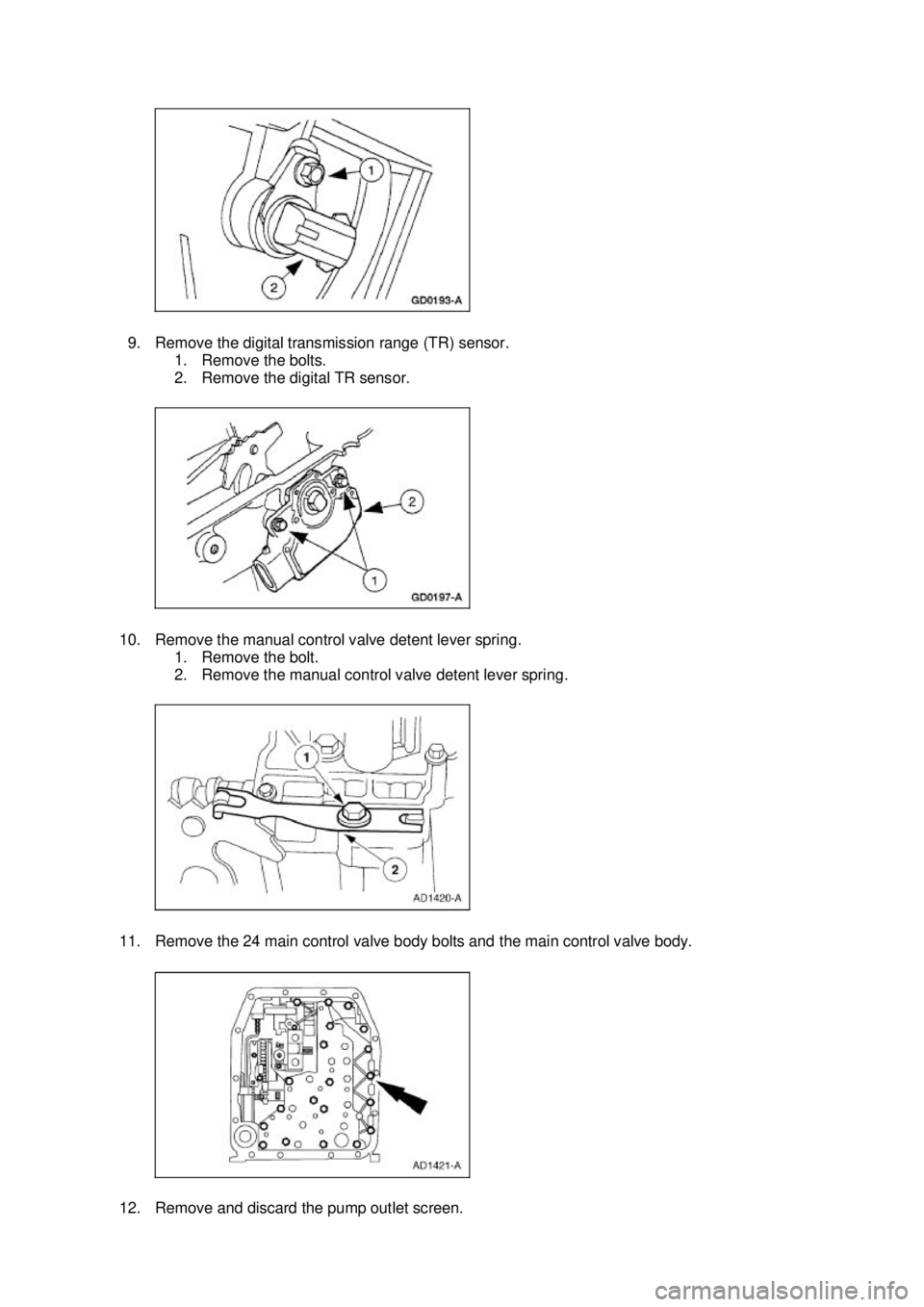
9. Remove the digital transmission range (TR) sensor.
1. Remove the bolts.
2. Remove the digital TR sensor.
10. Remove the manual control valve detent lever spring. 1. Remove the bolt.
2. Remove the manual control valve detent lever spring.
11. Remove the 24 main control valve body bolts and the main control valve body.
12. Remove and discard the pump outlet screen. �K�l�j . 5 �b�a
162003 Mustang Workshop Manual
18. 11. 2011file:///C:/Ford/2000 - 2004/tsocache/SHEF_2748/S3B~us~en~ ...
Page 2552 of 4378
ASSEMBLY
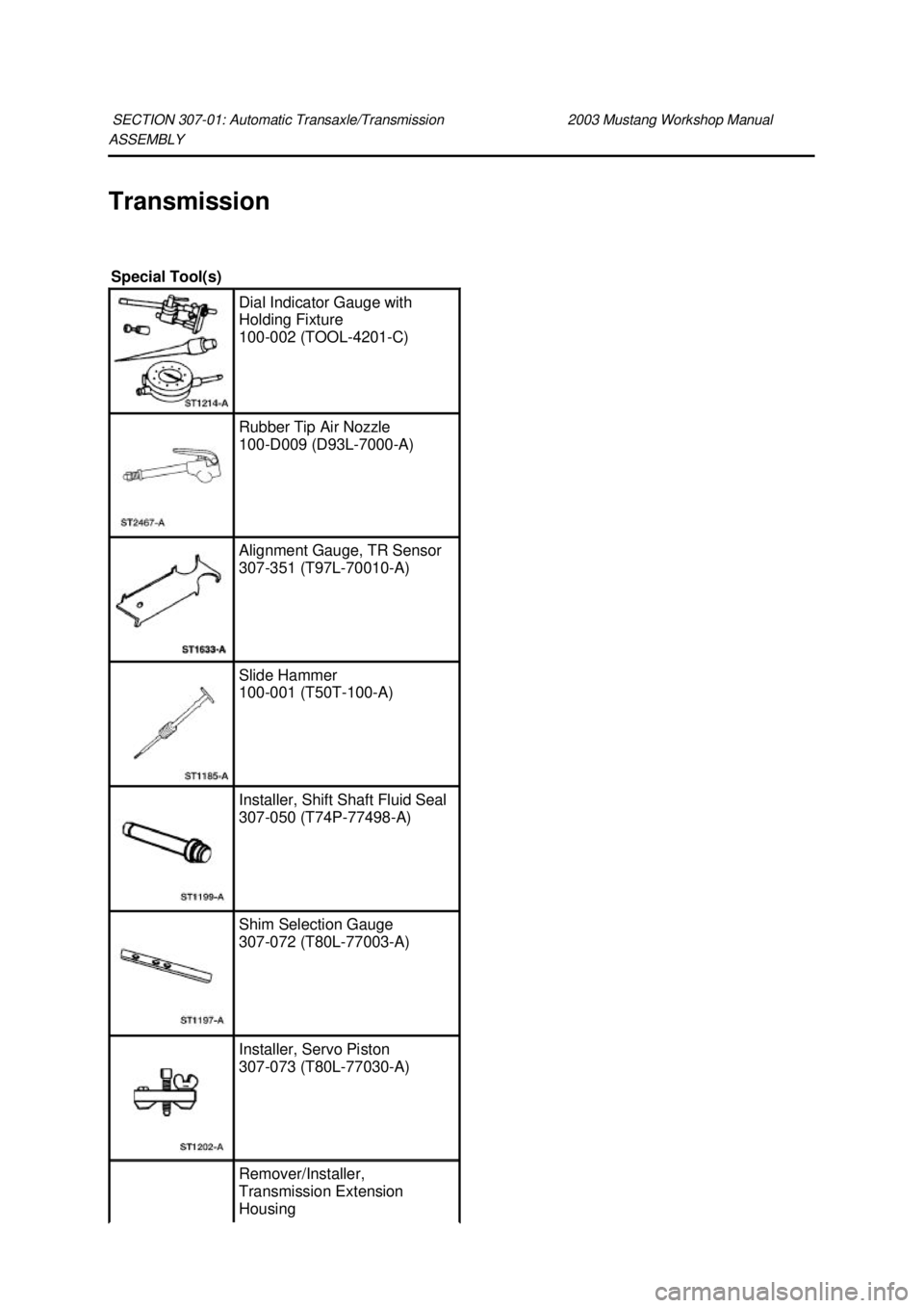
Transmission
SECTION 307-
01: Automatic Transaxle/Transmission 2003 Mustang Workshop Manual Special Tool(s)
Dial Indicator Gauge with
Holding Fixture
100-
002 (TOOL- 4201-C) Rubber Tip Air Nozzle
100-
D009 (D93L-7000- A) Alignment Gauge, TR Sensor
307-
351 (T97L-70010- A) Slide Hammer
100-
001 (T50T-100- A) Installer, Shift Shaft Fluid Seal
307-
050 (T74P-77498- A) Shim Selection Gauge
307-
072 (T80L-77003- A) Installer, Servo Piston
307-
073 (T80L-77030- A) Remover/Installer,
Transmission Extension
Housing �K�l�j . 1 �b�a
252003 Mustang Workshop Manual
18. 11. 2011file:///C:/Ford/2000 - 2004/tsocache/SHEF_2748/S3B~us~en~ ...
Page 2564 of 4378
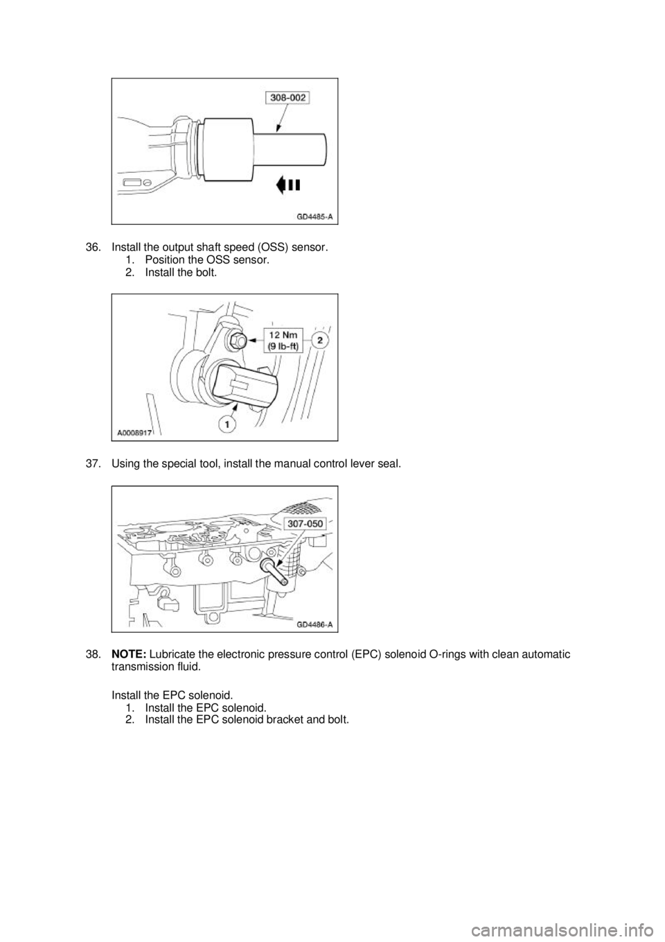
36. Install the output shaft speed (OSS) sensor.
1. Position the OSS sensor.
2. Install the bolt.
37. Using the special tool, install the manual control lever seal.
38. NOTE: Lubricate the electronic pressure control (EPC) solenoid O- rings with clean automatic
transmission fluid.
Install the EPC solenoid.
1. Install the EPC solenoid.
2. Install the EPC solenoid bracket and bolt. �K�l�j . 13 �b�a
252003 Mustang Workshop Manual
18. 11. 2011file:///C:/Ford/2000 - 2004/tsocache/SHEF_2748/S3B~us~en~ ...
Page 2574 of 4378
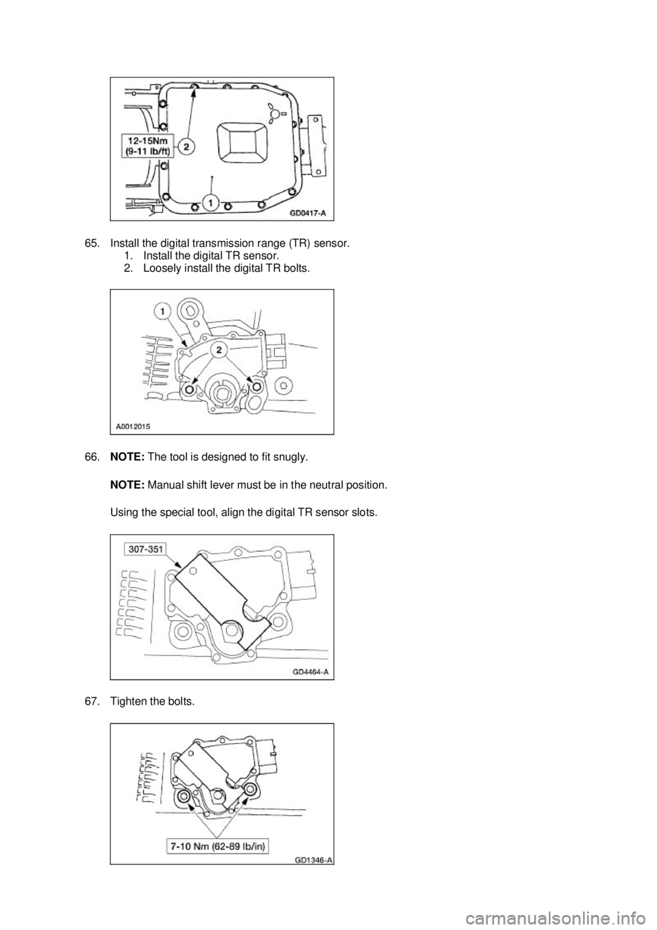
65. Install the digital transmission range (TR) sensor.
1. Install the digital TR sensor.
2. Loosely install the digital TR bolts.
66. NOTE: The tool is designed to fit snugly.
NOTE: Manual shift lever must be in the neutral position.
Using the special tool, align the digital TR sensor slots.
67. Tighten the bolts. �K�l�j . 23 �b�a
252003 Mustang Workshop Manual
18. 11. 2011file:///C:/Ford/2000 - 2004/tsocache/SHEF_2748/S3B~us~en~ ...
