FORD MUSTANG 2003 Manual PDF
MUSTANG 2003
FORD
FORD
https://www.carmanualsonline.info/img/11/56942/w960_56942-0.png
FORD MUSTANG 2003 Manual PDF
Page 1201 of 4378
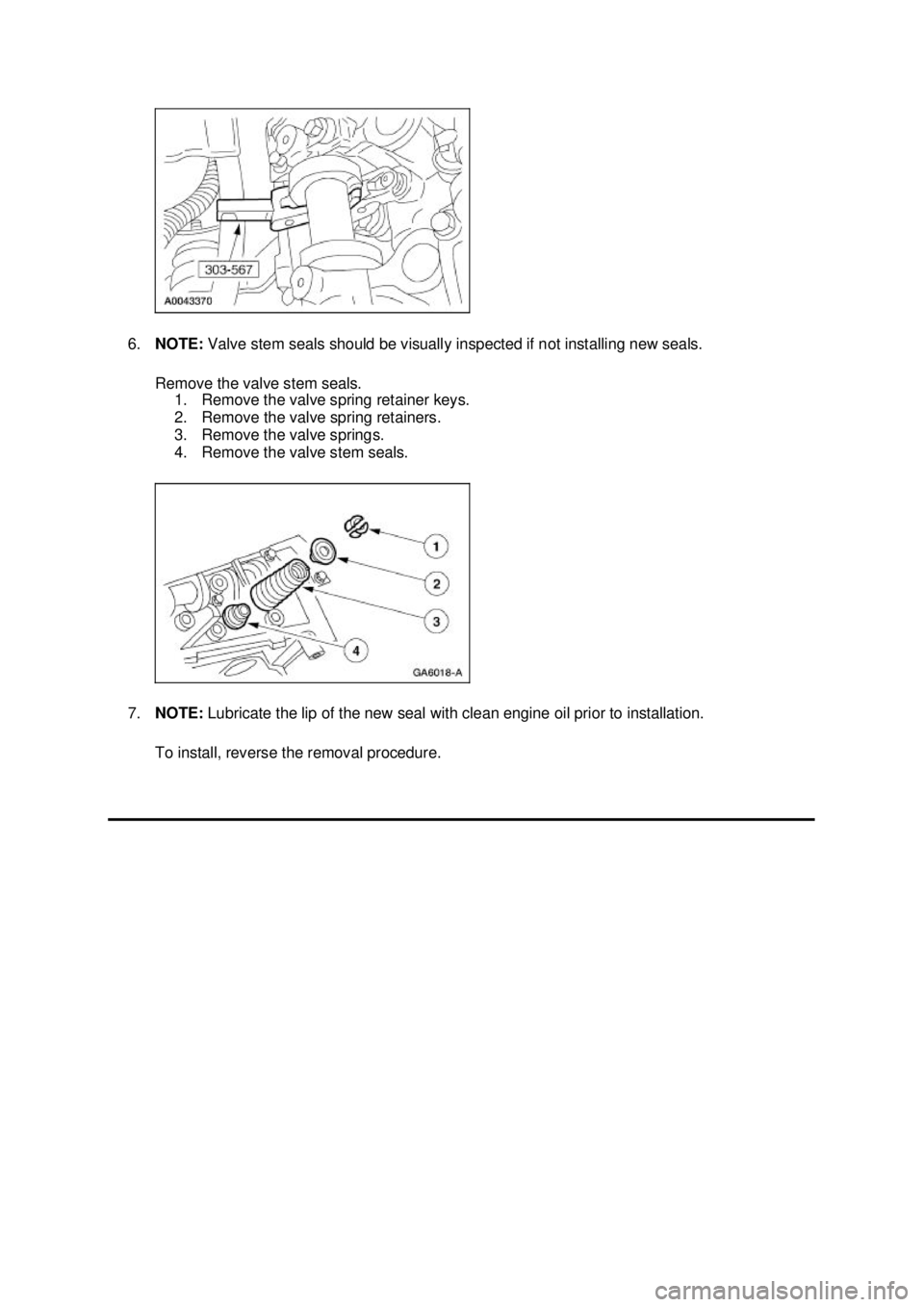
6.
NOTE: Valve stem seals should be visually inspected if not installing new seals.
Remove the valve stem seals. 1. Remove the valve spring retainer keys.
2. Remove the valve spring retainers.
3. Remove the valve springs.
4. Remove the valve stem seals.
7. NOTE: Lubricate the lip of the new seal with clean engine oil prior to installation.
To install, reverse the removal procedure. �K�l�j . 2 �b�a
22003 Mustang Workshop Manual
17. 11. 2011file:///C:/Ford/2000 - 2004/tsocache/SHEF_4464/S3B~us~en~ ...
Page 1256 of 4378
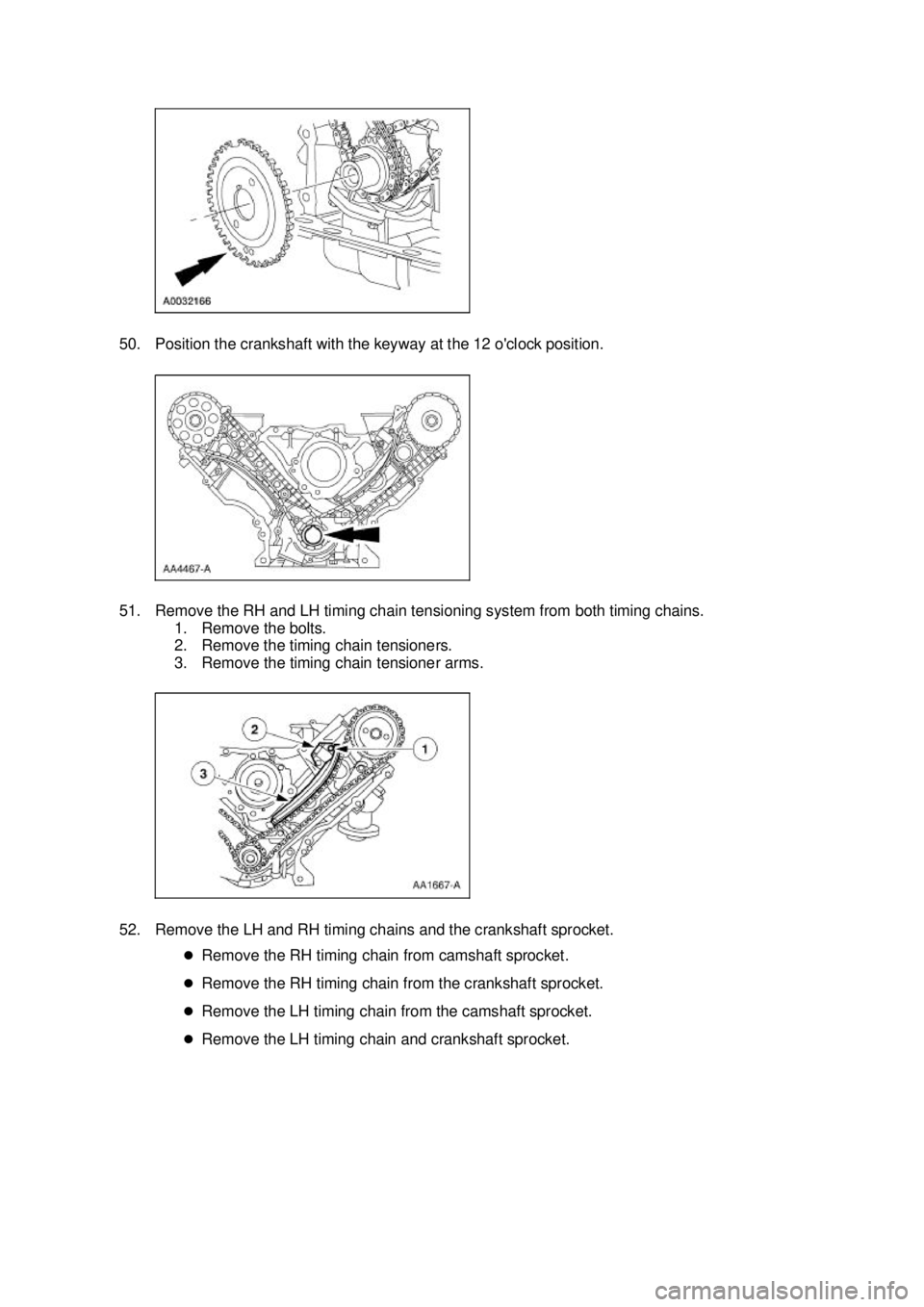
50. Position the crankshaft with the keyway at the 12 o'clock position.
51. Remove the RH and LH timing chain tensioning system from both timing chains.
1. Remove the bolts.
2. Remove the timing chain tensioners.
3. Remove the timing chain tensioner arms.
52. Remove the LH and RH timing chains and the crankshaft sprocket. �zRemove the RH timing chain from camshaft sprocket.
�z Remove the RH timing chain from the crankshaft sprocket.
�z Remove the LH timing chain from the camshaft sprocket.
�z Remove the LH timing chain and crankshaft sprocket. �K�l�j . 16 �b�a
212003 Mustang Workshop Manual
17. 11. 2011file:///C:/Ford/2000 - 2004/tsocache/SHEF_4464/S3B~us~en~ ...
Page 1299 of 4378
3. Using the special tool, compress the valve spring.
4. Remove the valves.
1. Remove the valve spring retainer keys.
2. Remove the valve spring retainers.
3. Remove the valve spring.
4. Remove the valves.
5. Remove the hydraulic lash adjusters.
6. Remove the bolts and the camshaft bearing caps. �K�l�j . 2 �b�a
42003 Mustang Workshop Manual
17. 11. 2011file:///C:/Ford/2000 - 2004/tsocache/SHEF_4464/S3B~us~en~ ...
Page 1318 of 4378
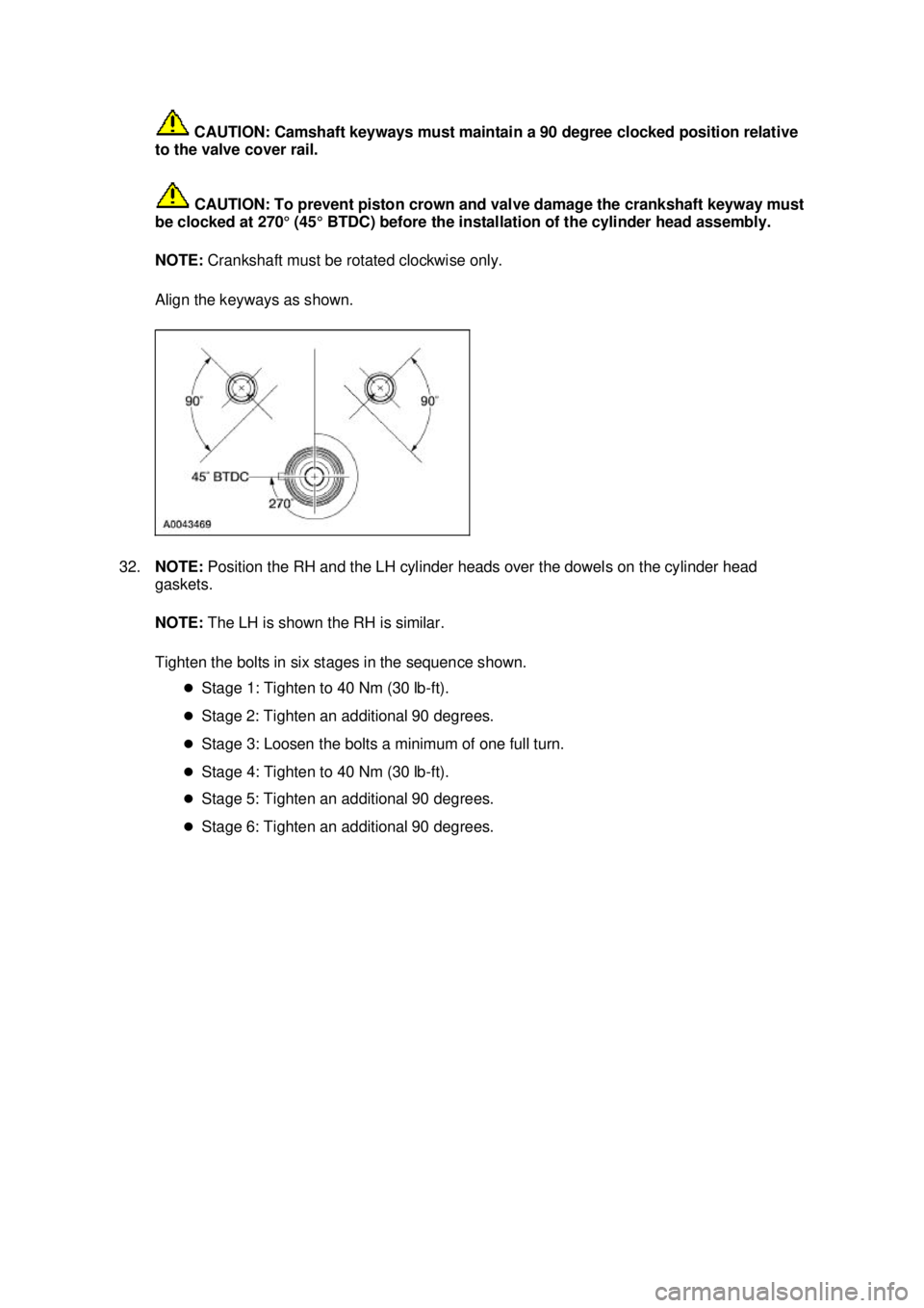
CAUTION: Camshaft keyways must maintain a 90 degree clocked position relative
to the valve cover rail.
CAUTION: To prevent piston crown and valve damage the crankshaft keyway must
be clocked at 270° (45° BTDC) before the installation of the cylinder head assembly.
NOTE: Crankshaft must be rotated clockwise only.
Align the keyways as shown.
32. NOTE: Position the RH and the LH cylinder heads over the dowels on the cylinder head
gaskets.
NOTE: The LH is shown the RH is similar.
Tighten the bolts in six stages in the sequence shown. �zStage 1: Tighten to 40 Nm (30 lb- ft).
�z Stage 2: Tighten an additional 90 degrees.
�z Stage 3: Loosen the bolts a minimum of one full turn.
�z Stage 4: Tighten to 40 Nm (30 lb- ft).
�z Stage 5: Tighten an additional 90 degrees.
�z Stage 6: Tighten an additional 90 degrees. �K�l�j . 14 �b�a
362003 Mustang Workshop Manual
17. 11. 2011file:///C:/Ford/2000 - 2004/tsocache/SHEF_4464/S3B~us~en~ ...
Page 1327 of 4378
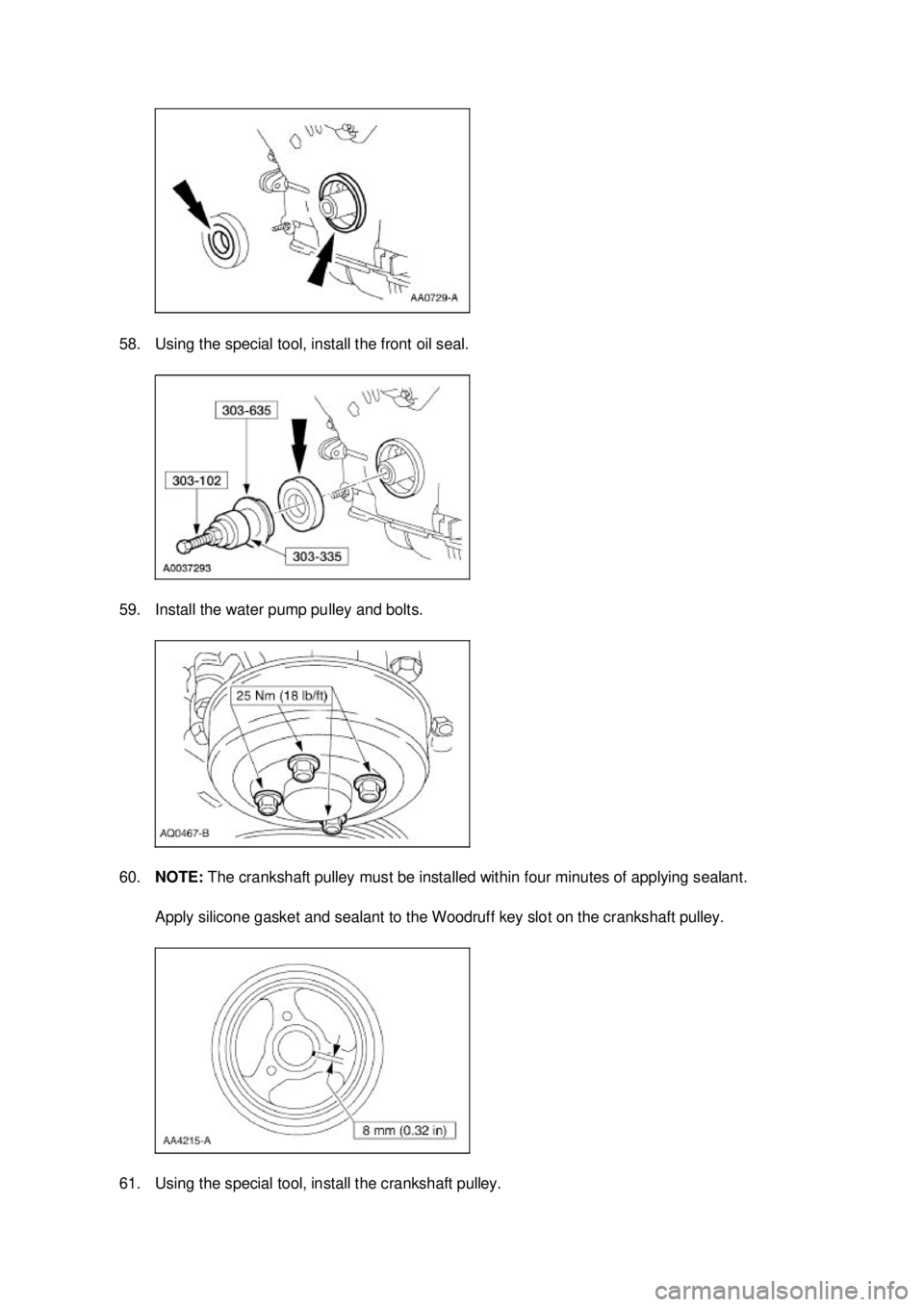
58. Using the special tool, install the front oil seal.
59. Install the water pump pulley and bolts.
60.
NOTE: The crankshaft pulley must be installed within four minutes of applying sealant.
Apply silicone gasket and sealant to the Woodruff key slot on the crankshaft pulley.
61. Using the special tool, install the crankshaft pulley. �K�l�j . 23 �b�a
362003 Mustang Workshop Manual
17. 11. 2011file:///C:/Ford/2000 - 2004/tsocache/SHEF_4464/S3B~us~en~ ...
Page 1353 of 4378
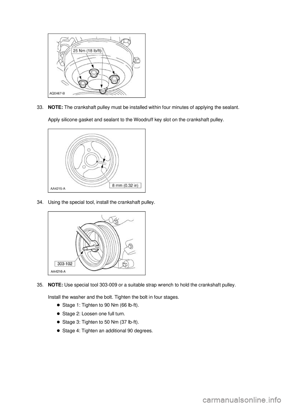
33.
NOTE: The crankshaft pulley must be installed within four minutes of applying the sealant.
Apply silicone gasket and sealant to the Woodruff key slot on the crankshaft pulley.
34. Using the special tool, install the crankshaft pulley.
35. NOTE: Use special tool 303- 009 or a suitable strap wrench to hold the crankshaft pulley.
Install the washer and the bolt. Tighten the bolt in four stages. �zStage 1: Tighten to 90 Nm (66 lb- ft).
�z Stage 2: Loosen one full turn.
�z Stage 3: Tighten to 50 Nm (37 lb- ft).
�z Stage 4: Tighten an additional 90 degrees. �K�l�j . 13 �b�a
252003 Mustang Workshop Manual
17. 11. 2011file:///C:/Ford/2000 - 2004/tsocache/SHEF_4464/S3B~us~en~ ...
Page 1400 of 4378
8 6K258 Stud (4 req'd)
9 6687 Oil pan baffle
10 N806180 Spacer
11 N605904 Bolt
12 6710 Oil pan gasket
13 6675 Oil pan
14 W701240 Bolt (16 req'd)
15 6622 Oil pump screen pickup and tube
16 N806155 Bolt (2 req'd)
17 N811280 Spacer (3 req'd)
18 6345 Bolt (6 req'd)
19 6C360 Main bearing cap adjusting screw (10 req'd)
20 6A338 Crankshaft main bearing (4 req'd)
21 N806201 Woodruff key
22 6621 Oil pump
23 N806183 Bolt (4 req'd)
24 6333 Crankshaft main bearing
25 8501 Water pump �K�l�j . 16 �b�a
162003 Mustang Workshop Manual
17. 11. 2011file:///C:/Ford/2000 - 2004/tsocache/SHEF_4464/S3B~us~en~ ...
Page 1421 of 4378
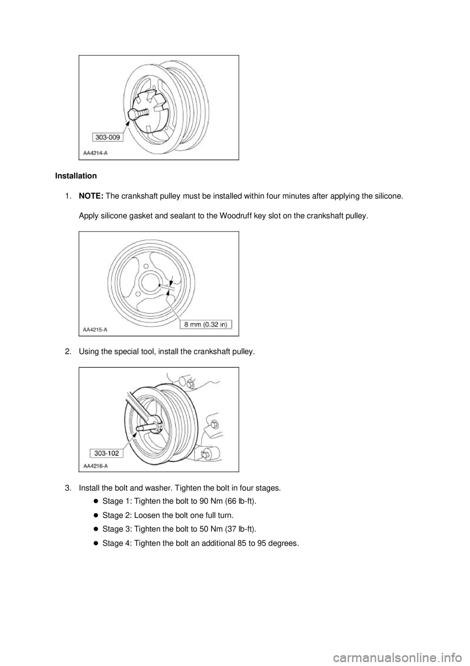
Installation
1. NOTE: The crankshaft pulley must be installed within four minutes after applying the silicone.
Apply silicone gasket and sealant to the Woodruff key slot on the crankshaft pulley.
2. Using the special tool, install the crankshaft pulley.
3. Install the bolt and washer. Tighten the bolt in four stages. �zStage 1: Tighten the bolt to 90 Nm (66 lb- ft).
�z Stage 2: Loosen the bolt one full turn.
�z Stage 3: Tighten the bolt to 50 Nm (37 lb- ft).
�z Stage 4: Tighten the bolt an additional 85 to 95 degrees. �K�l�j . 2 �b�a
32003 Mustang Workshop Manual
17. 11. 2011file:///C:/Ford/2000 - 2004/tsocache/SHEF_4464/S3B~us~en~ ...
Page 1536 of 4378
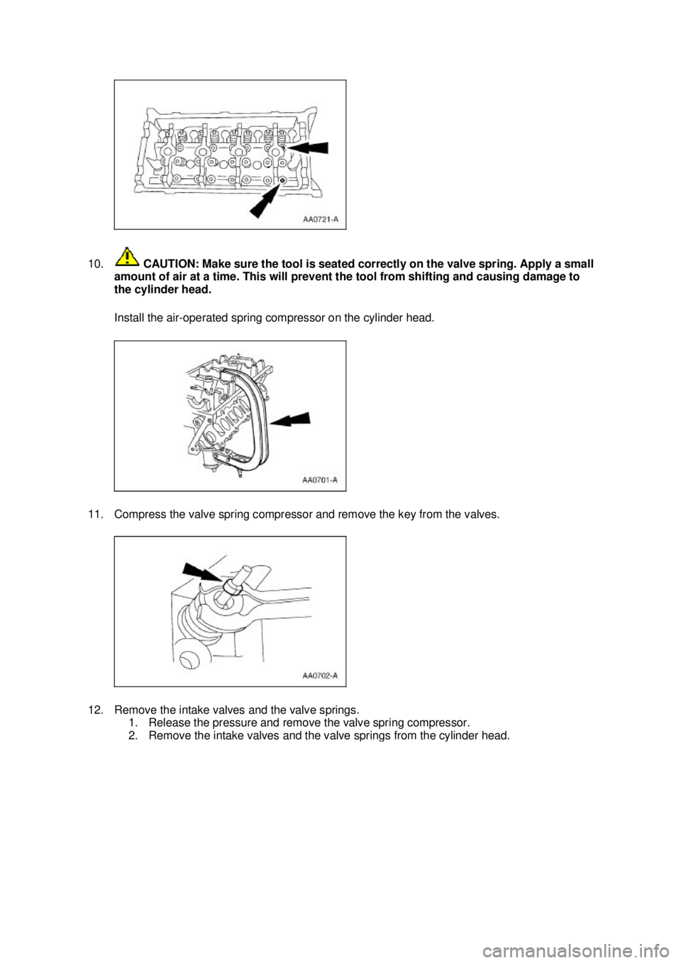
10.
CAUTION: Make sure the tool is seated correctly on the valve spring. Apply a small
amount of air at a time. This will prevent the tool from shifting and causing damage to
the cylinder head.
Install the air- operated spring compressor on the cylinder head.
11. Compress the valve spring compressor and remove the key from the valves.
12. Remove the intake valves and the valve springs. 1. Release the pressure and remove the valve spring compressor. 2. Remove the intake valves and the valve springs from the cylinder head. �K�l�j . 4 �b�a
112003 Mustang Workshop Manual
17. 11. 2011file:///C:/Ford/2000 - 2004/tsocache/SHEF_4464/S3B~us~en~ ...
Page 1539 of 4378
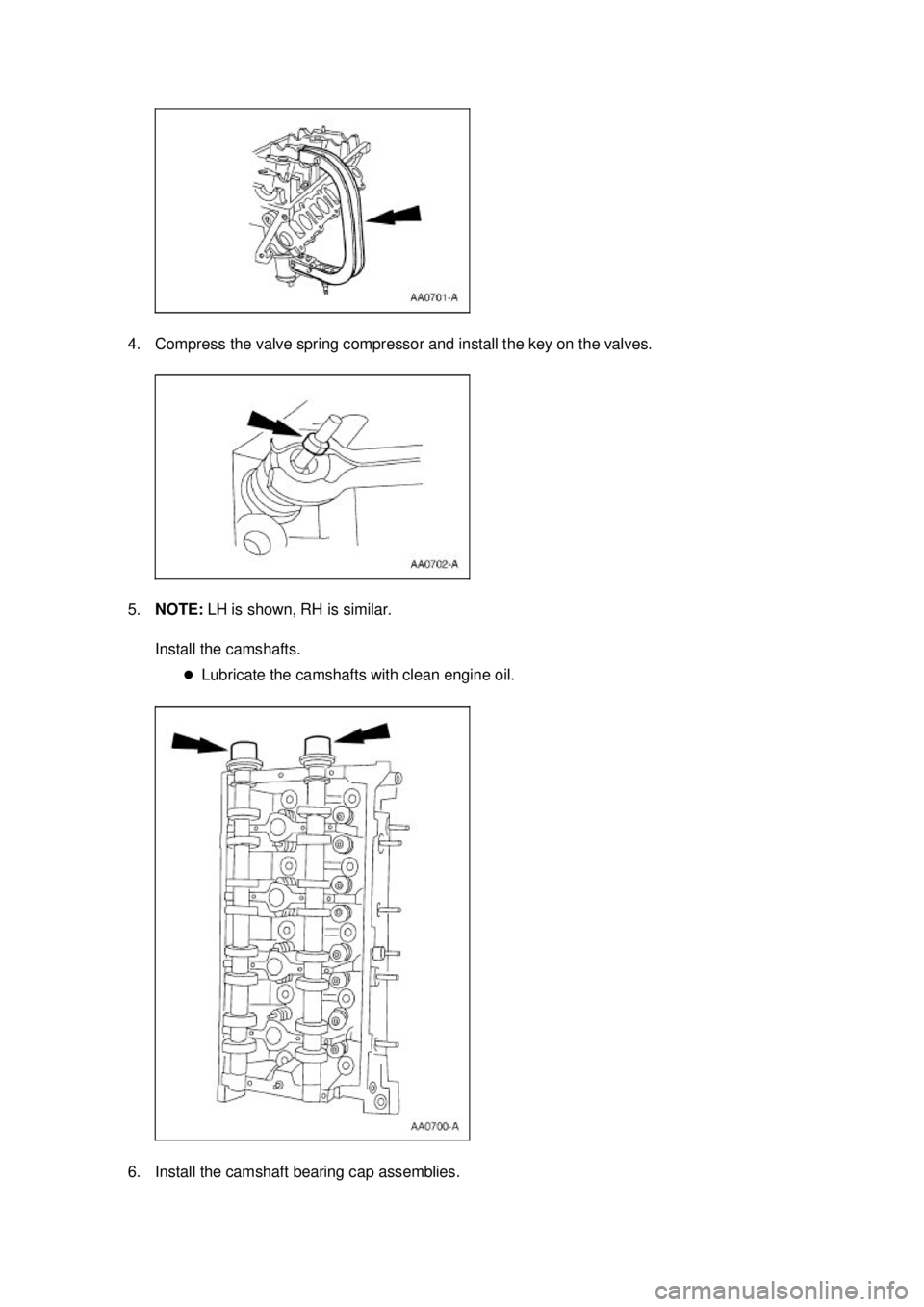
4. Compress the valve spring compressor and install the key on the valves.
5.
NOTE: LH is shown, RH is similar.
Install the camshafts. �zLubricate the camshafts with clean engine oil.
6. Install the camshaft bearing cap assemblies. �K�l�j . 7 �b�a
112003 Mustang Workshop Manual
17. 11. 2011file:///C:/Ford/2000 - 2004/tsocache/SHEF_4464/S3B~us~en~ ...
