engine FORD TRANSIT 2006 7.G Body And Equipment Mounting Section Manual
[x] Cancel search | Manufacturer: FORD, Model Year: 2006, Model line: TRANSIT, Model: FORD TRANSIT 2006 7.GPages: 234, PDF Size: 33.19 MB
Page 146 of 234
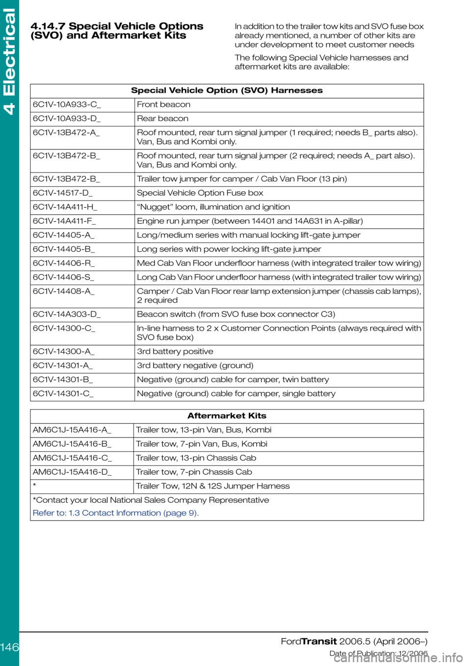
4.14.7 Special Vehicle Options
(SVO) and Aftermarket Kits
In addition to the trailer tow kits and SVO fuse box
already mentioned, a number of other kits are
under development to meet customer needs
The following Special Vehicle harnesses and
aftermarket kits are available:
Special Vehicle Option (SVO) Harnesses
Front beacon6C1V-10A933-C_
Rear beacon6C1V-10A933-D_
Roof mounted, rear turn signal jumper (1 required; needs B_ parts also).
Van, Bus and Kombi only.
6C1V-13B472-A_
Roof mounted, rear turn signal jumper (2 required; needs A_ part also).
Van, Bus and Kombi only.
6C1V-13B472-B_
Trailer tow jumper for camper / Cab Van Floor (13 pin)6C1V-13B472-B_
Special Vehicle Option Fuse box6C1V-14517-D_
“Nugget” loom, illumination and ignition6C1V-14A411-H_
Engine run jumper (between 14401 and 14A631 in A-pillar)6C1V-14A411-F_
Long/medium series with manual locking lift-gate jumper6C1V-14405-A_
Long series with power locking lift-gate jumper6C1V-14405-B_
Med Cab Van Floor underfloor harness (with integrated trailer tow wiring)6C1V-14406-R_
Long Cab Van Floor underfloor harness (with integrated trailer tow wiring)6C1V-14406-S_
Camper / Cab Van Floor rear lamp extension jumper (chassis cab lamps),
2 required
6C1V-14408-A_
Beacon switch (from SVO fuse box connector C3)6C1V-14A303-D_
In-line harness to 2 x Customer Connection Points (always required with
SVO fuse box)
6C1V-14300-C_
3rd battery positive6C1V-14300-A_
3rd battery negative (ground)6C1V-14301-A_
Negative (ground) cable for camper, twin battery6C1V-14301-B_
Negative (ground) cable for camper, single battery6C1V-14301-C_
Aftermarket Kits
Trailer tow, 13-pin Van, Bus, KombiAM6C1J-15A416-A_
Trailer tow, 7-pin Van, Bus, KombiAM6C1J-15A416-B_
Trailer tow, 13-pin Chassis CabAM6C1J-15A416-C_
Trailer tow, 7-pin Chassis CabAM6C1J-15A416-D_
Trailer Tow, 12N & 12S Jumper Harness*
*Contact your local National Sales Company Representative
Refer to: 1.3 Contact Information (page 9).
FordTransit 2006.5 (April 2006–)
Date of Publication: 12/2006
4 Electrical
146
Page 157 of 234
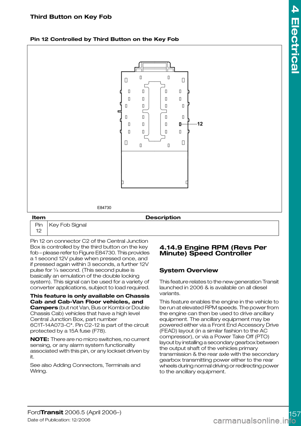
Third Button on Key Fob
Pin 12 Controlled by Third Button on the Key Fob
DescriptionItem
Key Fob SignalPin
12
Pin 12 on connector C2 of the Central Junction
Box is controlled by the third button on the key
fob – please refer to Figure E84730. This provides
a 1 second 12V pulse when pressed once, and
if pressed again within 3 seconds, a further 12V
pulse for ¼ second. (This second pulse is
basically an emulation of the double locking
system). This signal can be used for a variety of
converter applications, subject to load required.
This feature is only available on Chassis
Cab and Cab-Van Floor vehicles, and
Campers (but not Van, Bus or Kombi or Double
Chassis Cab) vehicles that have a high level
Central Junction Box, part number
6C1T-14A073-C*. Pin C2-12 is part of the circuit
protected by a 15A fuse (F78).
NOTE: There are no micro switches, no current
sensing, or any alarm system functionality
associated with this pin, or any lockset driven by
it.
See also Adding Connectors, Terminals and
Wiring.
4.14.9 Engine RPM (Revs Per
Minute) Speed Controller
System Overview
This feature relates to the new generation Transit
launched in 2006 & is available on all diesel
variants.
This feature enables the engine in the vehicle to
be run at elevated RPM speeds. The power from
the engine can then be used to drive ancillary
equipment. The ancillary equipment may be
powered either via a Front End Accessory Drive
(FEAD) layout (in a similar fashion to the AC
compressor), or via a Power Take Off (PTO)
layout by installing a secondary gearbox between
the output shaft of the vehicles primary
transmission & the rear axle with the secondary
gearbox transmitting power either to the rear
wheels during normal driving or redirecting power
to the ancillary equipment.
FordTransit 2006.5 (April 2006–)
Date of Publication: 12/2006
4 Electrical
15712E84730
Page 158 of 234
NOTE: A power take off layout can only be
implemented on vehicles fitted with an ABS
braking system. Manual braking systems employ
a transmission speed sensor to determine vehicle
speed & the RPM speed control software
contains vehicle speed restrictions which prohibit
RPM speed control operation if vehicle speed is
detected above very low levels (approx 2.5 mph).
A vehicle fitted with an ABS braking system
derives vehicle speed via the vehicles wheel
speed sensors, so the transmission can operate
normally without effecting RPM speed control
operation.
3 Modes of Operation
There are 3 principle modes in which this feature
can operate, they are:
1.3 speed mode – this provides the end user a
choice of up to 3 preset RPM values to select
from. The end user cannot easily override
these values so there is minimal risk of damage
to ancillary equipment due to it being run at
speeds it was not designed for. Very limited
vehicle speed is allowable while in this mode
(up to 2.5mph approx)
2.Variable speed mode – this provides the end
user with RPM speed ramp up & down
buttons. The end user is free to select RPM
values between 1300-3000rpm in 25rpm
steps. A single press results in a 25 rpm jump.
If a ramp button is held depressed by the end
user then the rate of change is 250rpm/sec.
Very limited vehicle speed is allowable while in
this mode (up to 2.5mph approx)
3.Idle up speed – this mode allows the engines
normal idle to be increased to any value (in 25
rpm steps) in the range 900-1200rpm. There
is not a vehicle speed restriction in this mode
as the intended use is to raise the engine idle
to reduce the likelihood of engine stall when
ancillary equipment is being run from the
engine during normal drive operations. Eg
refrigerator units used to keep the cargo bay
cool.
NOTE: Items 1) & 2) will be available from Nov
2006, while item 3) should be available from Jan
2007. Any latest generation diesel Transit can be
updated to include item 3) Idle up speed with a
simple calibration update once it becomes
available.
System Availability
This feature is built into the latest Powertrain
Control Module (PCM) software on all diesel
engine variants.
By default the feature is not enabled unless the
vehicle is specifically ordered with the feature
from the factory.
Vehicles which have not been ordered with this
feature may have the feature enabled at a dealer
via the IDS diagnostics system. The dealer should
charge for this service.
How to control this feature
A loop of wire (green/white) is provided in the
main electrical loom to permit control of the RPM
Speed Control software. Cutting this loop will
provide two wires to connect a control box to the
PCM.
The control box needs to switch resistors into the
circuit across the two green/white wires which
formally formed the loop prior to being cut. This
sort of circuit is known as a resistance ladder. The
PCM software monitors the green/white wire
circuit & when certain resistances are detected
they are interpreted as various inputs which
control the feature. The switch box can be
located where it’s ideally required for the vehicle
conversion in question, rather than having to be
mounted on the Instrument Panel (IP). If the
converter chooses to locate the switch box in a
location which is subject to an adverse
environment then the converter should design
the switch box to withstand with these conditions.
How to locate the green/white loop
The main electrical loom enters the vehicle cab
from the engine bay on the left hand side of the
vehicle via a large diameter hole in the engine bay
/ cabin bulkhead. This hole is just above the left
hand front suspension turret. See following Figure
E88307
FordTransit 2006.5 (April 2006–)
Date of Publication: 12/2006
4 Electrical
158
Page 160 of 234
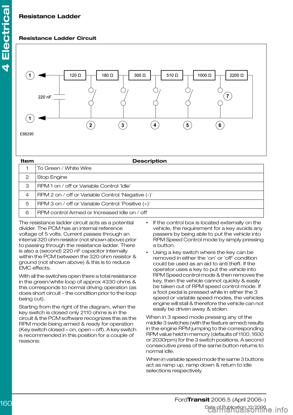
Resistance Ladder
Resistance Ladder Circuit
DescriptionItem
To Green / White Wire1
Stop Engine2
RPM 1 on / off or Variable Control 'Idle'3
RPM 2 on / off or Variable Control 'Negative (-)'4
RPM 3 on / off or Variable Control 'Positive (+)'5
RPM control Armed or Increased Idle on / off6
The resistance ladder circuit acts as a potential
divider. The PCM has an internal reference
voltage of 5 volts. Current passes through an
internal 320 ohm resistor (not shown above) prior
to passing through the resistance ladder. There
is also a (second) 220 nF capacitor internally
within the PCM between the 320 ohm resistor &
ground (not shown above) & this is to reduce
EMC effects.
With all the switches open there a total resistance
in the green/white loop of approx 4330 ohms &
this corresponds to normal driving operation (as
does short circuit – the condition prior to the loop
being cut).
Starting from the right of the diagram, when the
key switch is closed only 2110 ohms is in the
circuit & the PCM software recognizes this as the
RPM mode being armed & ready for operation
(Key switch closed = on, open = off). A key switch
is recommended in this position for a couple of
reasons:
•If the control box is located externally on the
vehicle, the requirement for a key avoids any
passers by being able to put the vehicle into
RPM Speed Control mode by simply pressing
a button.
•Using a key switch where the key can be
removed in either the ‘on’ or ‘off’ condition
could be used as an aid to anti theft. If the
operator uses a key to put the vehicle into
RPM Speed control mode & then removes the
key, then the vehicle cannot quickly & easily
be taken out of RPM speed control mode. If
a foot pedal is pressed while in either the 3
speed or variable speed modes, the vehicles
engine will stall & therefore the vehicle can not
easily be driven away & stolen.
When in 3 speed mode pressing any of the
middle 3 switches (with the feature armed) results
in the engine RPM jumping to the corresponding
RPM value held in memory (defaults of 1100, 1600
or 2030rpm) for the 3 switch positions. A second
consecutive press of the same button returns to
normal idle.
When in variable speed mode the same 3 buttons
act as ramp up, ramp down & return to idle
selections respectively.
FordTransit 2006.5 (April 2006–)
Date of Publication: 12/2006
4 Electrical
16065432E88295711
Page 161 of 234
The software in the PCM responds to the change
of state, so it is recommended that these 3
middle switches be non-latching push button
micro switches. When going from idle to an
elevated RPM the execution of the command
will occur as the button is released. When going
to idle the execution of the command occurs as
the button is pressed.
The final button (the one on the left in Fig. 4) acts
as an ‘emergency’ vehicle engine stop. It is
recommended that this be a red & oversize
non-latching micro switch button. The execution
of this command will occur as the button is
pressed.
All wiring connecting the PCM to the resistance
ladder control box should be shielded & twisted
(33 twists / m) to reduce EMC effects
All resistors should have a tolerance of +/- 5% or
better
Switch contact, connectors & loom (loom
between the green/white wires & the control
box) total resistance must be no greater than 5
ohm max.
The PCM to resister ladder control switch box
loom should not come within 100mm of any other
harness, especially any carrying heavy loads.
Designs which do not require all the button
switches must still have the complete resistor
network with the switches positioned correctly
within the network.
The resistance ladder is acting as a potential
divider
The 220 nF capacitor is used in the circuit to
reduce EMC effects on the system
A suitable two way quality connector should be
used to connect the control box to the two
green/white wires
How to change the default settings
By default, when the feature is first enabled
(either via factory order or via dealer IDS tools),
it will be set to the 3 speed mode of operation
with preset RPM values of 1100, 1600 & 2030rpm
for the 3 speeds.
There are two methods by which these defaults
can be modified:
1.via the IDS diagnostics system at a Ford dealer
(there may be a charge for this)
2.via an inbuilt vehicle ‘learn mode’
Via the IDS system the mode of operation can
freely be changed between any of the 3 modes
of operation, the feature can even be turn off
(disabled). The 3 default RPM speeds can also
be modified.
Via the vehicle ‘learn mode’ the 3 speed mode
& the variable speed mode can be freely
interchanged, however it is not possible to select
the idle up speed mode via the vehicle learn
mode. The 3 default RPM speeds can also be
modified via ‘learn mode’
It is not possible via either method above, to
change the step value of 25rpm per press or the
250 rpm per sec for a held down button, in the
variable rpm speed mode.
Via IDS The RPM Speed Controller menu is under
the tool box tab, then Powertrain, then service
functions, then PCM. The IDS on screen menus
will guide the dealer through the options & setup.
How to enter vehicle ‘Learn mode’
1.Make sure that the RPM Speed controller
switch box is connected but turned off (not
‘armed’)
2.Start the engine (vehicle out of gear & no foot
pedals being pressed, handbrake on)
3.Wait a couple of seconds for the instrument
panel start up diagnostic lights to extinguish
4.Press & release the clutch pedal
5.Press & release the brake pedal
6.Repeat steps 4) & 5) a further four times
(clutch & brake pressed a total of five times
sequentially each)
NOTE: Steps 4) to 6) have to be started within
10 seconds of the engine start
The vehicle should now be in ‘learn mode’
How to Select between modes
1.Enter ‘learn mode’ (see directions above)
2.Arm the RPM speed controller (turn the key
switch to ‘on’)
If the vehicle is already in 3 speed mode (the
initial default):
3.Press & release the brake pedal five times
The vehicle should now be in variable speed
mode. The new settings can be saved & learn
mode exited (see below)
Alternatively
4.Press & release the brake pedal once
The vehicle should now be in 3 speed mode.
The new settings can be saved & learn mode
exited (see below)
Using this method it is easy to change between
these two modes of operation for the RPM
speed controller
NOTE: If the engine stalls out at the initial brake
pedal input then the vehicle was not in, or has
dropped out of ‘learn mode’ & you will have to
restart the procedure.
FordTransit 2006.5 (April 2006–)
Date of Publication: 12/2006
4 Electrical
161
Page 162 of 234
How to change the 3 pre-set default
RPM values in the 3 speed mode
1.Enter ‘learn mode’ (see directions above)
2.Arm the RPM speed controller (turn the key
switch to ‘on’)
3.Press & release the brake pedal once
4.Press & release the RPM button that requires
re-programming
5.Use the accelerator pedal to rev the engine to
the new desired RPM speed & hold at this
speed (only speeds between 1200 to 3000
rpm can be selected in 3 speed mode)
6.Press & release the same RPM button to reset
the stored RPM speed to the current engines
RPM
7.Release the accelerator pedal
8.Repeat steps 4) to 7) for the remaining RPM
buttons
The 3 RPM speeds should now be
re-programmed to the new RPM speeds. The
new settings can be saved & learn mode exited
(see below)
NOTE: If the engine RPM responds to the initial
RPM button press, then the vehicle has not
entered ‘learn mode’ correctly & you will have to
restart the procedure. If the engine stalls out at
the brake or accelerator pedal inputs then the
vehicle was not in, or has dropped out of ‘learn
mode’ & you will have to restart the procedure.
How to save new settings & exit
from ‘Learn mode’
1.From within the ‘learn mode’ & with the RPM
Speed Control switch box ‘armed’, press the
clutch pedal repeatedly until the engine stalls.
2.Restart the engine & test the new settings,
repeat above procedures if necessary
NOTE: The engine stalling indicates that the
settings should have been saved & the vehicle
has exited from ‘learn mode’. Learn mode
however is very specific that the exact steps are
taken in the correct order & within certain time
limits otherwise the learn procedure fails & it may
take several attempts to get this order & timing
correct & a successful modification from the
default settings.
Some Reasons why RPM speed
Control operation may stop or fail
The RPM Speed control software monitors
vehicle information during operation in RPM
speed control mode & will drop out of RPM speed
control and / or stall the engine should any
adverse signals be detected. For example:
•If the engine temperature becomes too hot
then RPM speed control will stop in order to
protect the engine.
•If the engine oil light illuminates then RPM
speed control will stop in order to protect the
engine
•If the low fuel level light illuminates then RPM
speed control will stop so that the vehicle can
be driven to a refueling point.
•If the vehicle speed exceeds approx 2.5 mph
wile in 3 speed or variable speed modes, then
RPM speed control may stop. RPM speed
control should normally be operated with the
hand brake on, but some uses may require a
low level of vehicle ‘creep’ during RPM speed
control operation. Note that there is no sensing
of the park brake on this version of RPM speed
controller to facilitate this type of operation.
•The software monitors for ‘stuck on’ buttons
on the control switch box, this may result in
RPM speed control being halted. A button that
is held down for too long may be registered
by the software as a ‘stuck’ button.
•The software monitors the foot pedals, if
depressed these may stall the engine if in 3
speed mode or variable speed mode (does
not apply to idle up speed)
•If the control switch box circuitry significantly
exceeds 2110 ohms or there is a short circuit
then RPM speed control will not be possible.
•If a PTO conversion has been attempted on a
vehicle with a non ABS braking system then
RPM speed control will fail due to vehicle
speed being registered via a transmission
speed sensor and / or the need to press the
clutch in order to put the vehicle in gear while
in RPM speed control mode.
4.14.10 Adding Connectors,
Terminals and Wiring
Additional Rear Speakers
NOTE: The connectors on the Instrument Panel
harness (14K024) and the main harness (14401)
are reversed between Left Hand Drive (LHD) and
Right Hand Drive (RHD) vehicles, hence different
sets of terminals/wires are required to cover all
the markets.
FordTransit 2006.5 (April 2006–)
Date of Publication: 12/2006
4 Electrical
162
Page 172 of 234
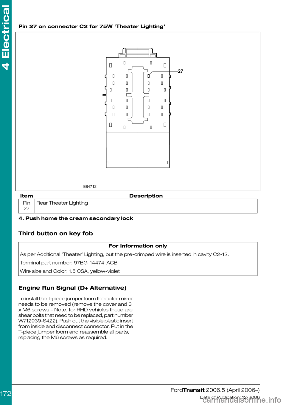
Pin 27 on connector C2 for 75W ‘Theater Lighting’
DescriptionItem
Rear Theater LightingPin
27
4. Push home the cream secondary lock
Third button on key fob
For Information only
As per Additional ‘Theater’ Lighting, but the pre-crimped wire is inserted in cavity C2-12.
Terminal part number: 97BG-14474-ACB
Wire size and Color: 1.5 CSA, yellow-violet
Engine Run Signal (D+ Alternative)
To install the T-piece jumper loom the outer mirror
needs to be removed (remove the cover and 3
x M6 screws – Note, for RHD vehicles these are
shear bolts that need to be replaced, part number
W712939-S422). Push out the visible plastic insert
from inside and disconnect connector. Put in the
T-piece jumper loom and reassemble all parts,
replacing the M6 screws as required.
FordTransit 2006.5 (April 2006–)
Date of Publication: 12/2006
4 Electrical
172E8471227
Page 173 of 234
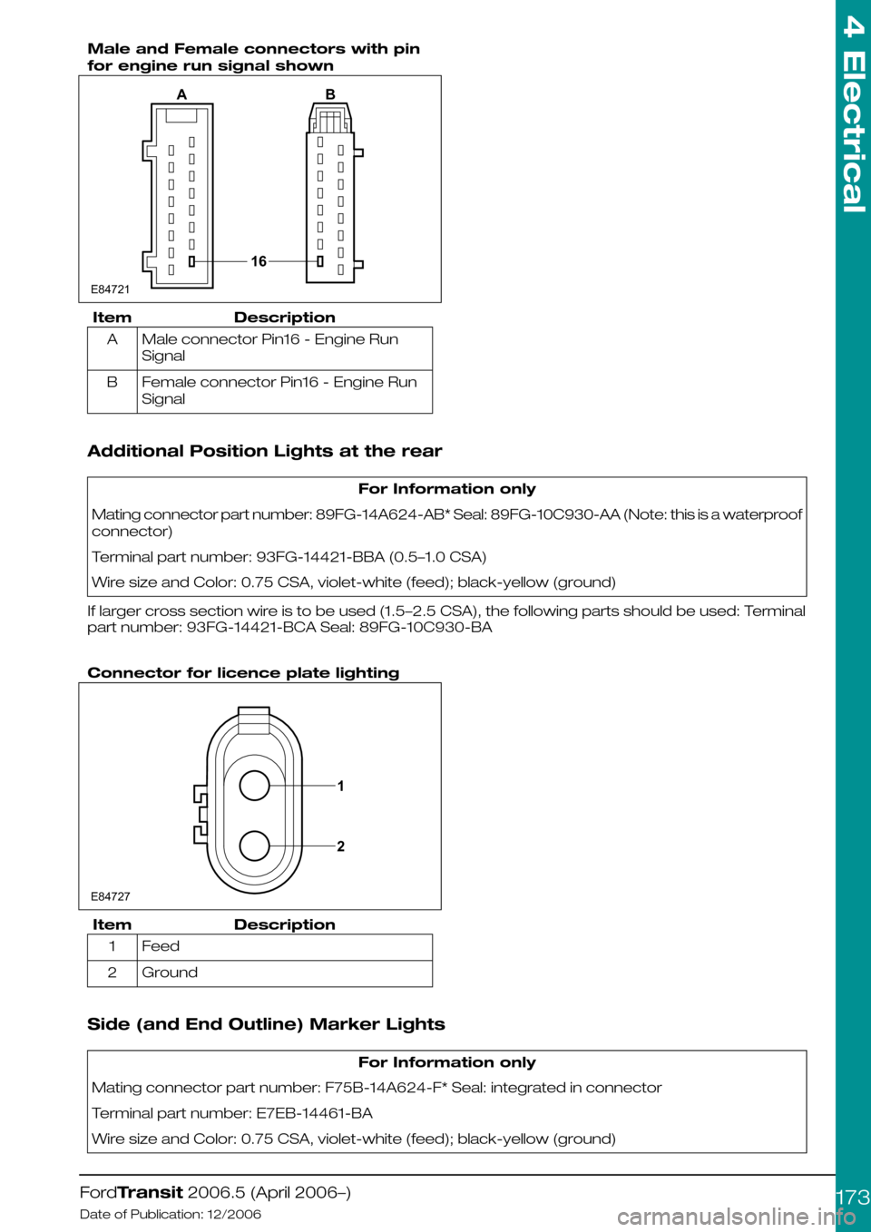
Male and Female connectors with pin
for engine run signal shown
DescriptionItem
Male connector Pin16 - Engine Run
Signal
A
Female connector Pin16 - Engine Run
Signal
B
Additional Position Lights at the rear
For Information only
Mating connector part number: 89FG-14A624-AB* Seal: 89FG-10C930-AA (Note: this is a waterproof
connector)
Terminal part number: 93FG-14421-BBA (0.5–1.0 CSA)
Wire size and Color: 0.75 CSA, violet-white (feed); black-yellow (ground)
If larger cross section wire is to be used (1.5–2.5 CSA), the following parts should be used: Terminal
part number: 93FG-14421-BCA Seal: 89FG-10C930-BA
Connector for licence plate lighting
DescriptionItem
Feed1
Ground2
Side (and End Outline) Marker Lights
For Information only
Mating connector part number: F75B-14A624-F* Seal: integrated in connector
Terminal part number: E7EB-14461-BA
Wire size and Color: 0.75 CSA, violet-white (feed); black-yellow (ground)
FordTransit 2006.5 (April 2006–)
Date of Publication: 12/2006
4 Electrical
173E8472116AB 1E847272
Page 190 of 234
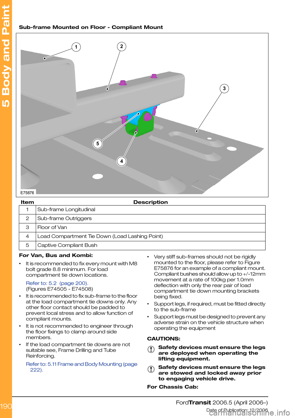
Sub-frame Mounted on Floor - Compliant Mount
DescriptionItem
Sub-frame Longitudinal1
Sub-frame Outriggers2
Floor of Van3
Load Compartment Tie Down (Load Lashing Point)4
Captive Compliant Bush5
For Van, Bus and Kombi:
•It is recommended to fix every mount with M8
bolt grade 8.8 minimum. For load
compartment tie down locations.
Refer to: 5.2 (page 200).
(Figures E74505 - E74508)
•It is recommended to fix sub-frame to the floor
at the load compartment tie downs only. Any
other floor contact should be padded to
prevent local stress and to allow function of
compliant mounts.
•It is not recommended to engineer through
the floor fixings to clamp around side
members.
•If the load compartment tie downs are not
suitable see, Frame Drilling and Tube
Reinforcing.
Refer to: 5.11 Frame and Body Mounting (page
222).
•Very stiff sub-frames should not be rigidly
mounted to the floor, please refer to Figure
E75876 for an example of a compliant mount.
Compliant bushes should allow up to +/-12mm
movement at a rate of 100kg per 1.0mm
deflection with only the rear pair of load
compartment tie down mounting brackets
being fixed.
•Support legs, if required, must be fitted directly
to the sub-frame
•Support legs must be designed to prevent any
adverse strain on the vehicle structure when
operating the equipment
CAUTIONS:
Safety devices must ensure the legs
are deployed when operating the
lifting equipment.
Safety devices must ensure the legs
are stowed and locked away prior
to engaging vehicle drive.
For Chassis Cab:
FordTransit 2006.5 (April 2006–)
Date of Publication: 12/2006
5 Body and Paint
190E7587642351
Page 192 of 234
For Chassis Cab with tail lift design as described
above it is recommended to use unique body
sub-frame for fixing to Chassis Cab structure. For
connection between sub-frame Chassis Cab
body structure please refer to Figure E74696.
For Chassis Cab with under-slung tail lift load
capacity is up to 1000kg at 1000mm from rear
end of chassis frame to center of load if mounted
and functioning on centre line of vehicle. If
mounted and functioning off center line or at the
side of the vehicle load capacity is reduced to
500kg at 1000mm from side/rear end to center
of load.
Greater off-sets and/or loads require additional
stabilizing equipment such as outriggers or
ground jacks. It is recommended not to increase
vehicle body stress over limit as given by load
factors above. If uncertain please consult your
local national sales representative or the Vehicle
Converter Advisory Service [email protected].
It is the Vehicle converters responsibility to fit a
decal to the converted vehicle stating that the
equipment must not be used without
outriggers/ground jacks in operating position. It
is also the vehicle converters responsibility to
guarantee safe functioning of the equipment.
For hydraulic tail lifts as used for general loading
or more specialized for wheel-chair lifts please
refer to Figure E75874.
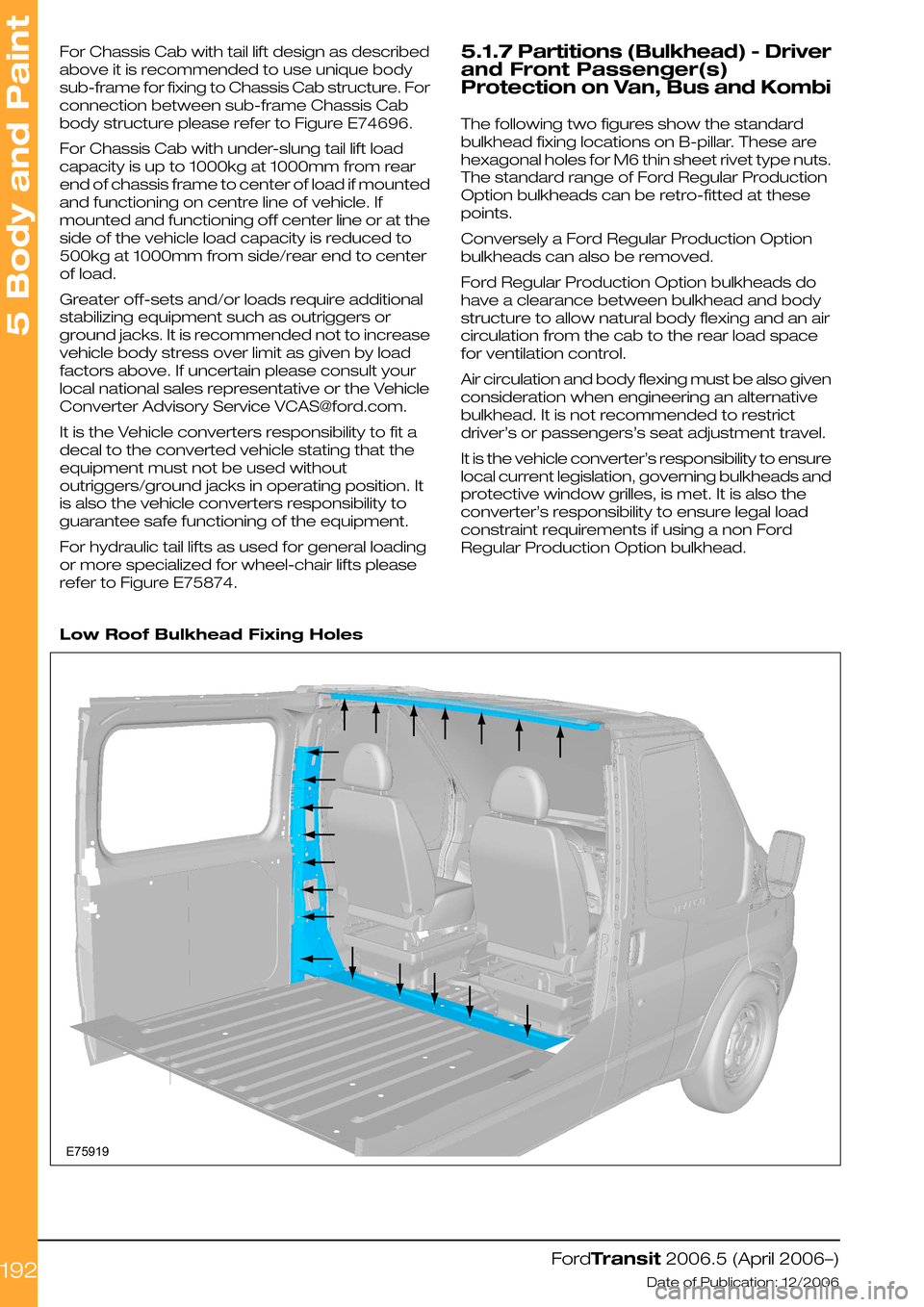
5.1.7 Partitions (Bulkhead) - Driver
and Front Passenger(s)
Protection on Van, Bus and Kombi
The following two figures show the standard
bulkhead fixing locations on B-pillar. These are
hexagonal holes for M6 thin sheet rivet type nuts.
The standard range of Ford Regular Production
Option bulkheads can be retro-fitted at these
points.
Conversely a Ford Regular Production Option
bulkheads can also be removed.
Ford Regular Production Option bulkheads do
have a clearance between bulkhead and body
structure to allow natural body flexing and an air
circulation from the cab to the rear load space
for ventilation control.
Air circulation and body flexing must be also given
consideration when engineering an alternative
bulkhead. It is not recommended to restrict
driver’s or passengers’s seat adjustment travel.
It is the vehicle converter’s responsibility to ensure
local current legislation, governing bulkheads and
protective window grilles, is met. It is also the
converter’s responsibility to ensure legal load
constraint requirements if using a non Ford
Regular Production Option bulkhead.
Low Roof Bulkhead Fixing Holes
FordTransit 2006.5 (April 2006–)
Date of Publication: 12/2006
5 Body and Paint
192E75919