engine FORD TRANSIT 2006 7.G Body And Equipment Mounting Section Manual
[x] Cancel search | Manufacturer: FORD, Model Year: 2006, Model line: TRANSIT, Model: FORD TRANSIT 2006 7.GPages: 234, PDF Size: 33.19 MB
Page 61 of 234
2.5 Driveshaft
2.5.1 Power Take Off
Gear Box add-on - Auxiliary
Propeller Drive Shaft
CAUTIONS:
Make sure that an inhibitor is fitted
to any modified vehicle that uses
the prop-shaft to power auxillary
equipment.
The only modification to the engine
control system (throttle, powertrain
control module and fuel pump)
recommended by the manufacturer
is the addition of an engine (RPM)
controller.
Do not weld or join onto any part of
the axle assembley.
The transmission oil temperature
must not exceed 130° during
operation of the Power Take Off
Where power is to be taken from the prop-shaft
for accessory drive, the engine controller can be
used in the same way as for the Front End
Accessory Drive (FEAD).
Refer to: 3.3 Accessory Drive (page 77).
Exceeding the recommended power take off
ratings may result in the engine over heating.
If the driveshaft is modified, it must be balanced
to a limit of 80gmm at 5000rpm and the
installation must not have universal joint angles
exceeding 4°. The gearbox output included angle
must be no more than 1°.
FordTransit 2006.5 (April 2006–)
Date of Publication: 12/2006
2 Chassis
61
Page 66 of 234
3.1 Engine
CAUTION: Make sure to follow the
equipment suppliers instructions for
safety, warranty and sometimes
legal compliance
For electrical supply to auxiliary equipment.
Refer to: 4.3 Charging System (page 95).
3.1.1 Engine Power Curves
The torque and power curves of the following
engines are shown in this section
•Common Rail 2.2L TCI 62.5kW (85HP) Diesel
Engine
•Common Rail 2.2L TCI 81kW (110HP) Diesel
Engine
•Common Rail 2.2L TCI 96kW (130HP) Diesel
Engine
•Common Rail 2.4L TCI 74kW (100HP) Diesel
Engine
•Common Rail 2.4L TCI 85kW (115HP) Diesel
Engine
•Common Rail 2.4L TCI 103kW (140HP) Diesel
Engine
•2.3L Gasoline engine 107kW (145HP)
FordTransit 2006.5 (April 2006–)
Date of Publication: 12/2006
3 Powertrain
66
Page 67 of 234
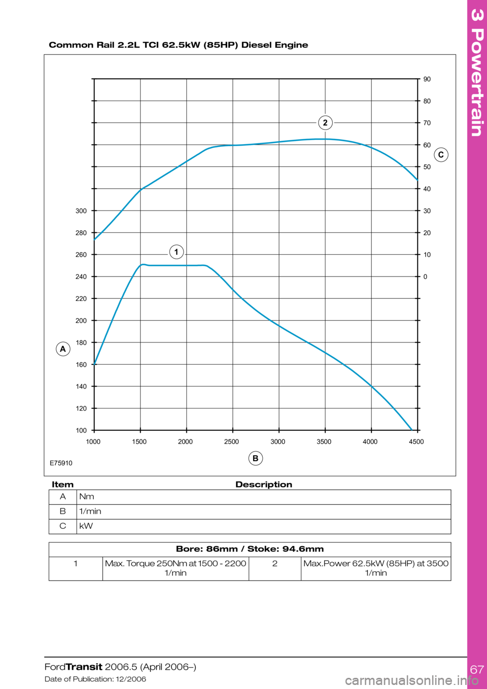
Common Rail 2.2L TCI 62.5kW (85HP) Diesel Engine
DescriptionItem
NmA
1/minB
kWC
Bore: 86mm / Stoke: 94.6mm
Max.Power 62.5kW (85HP) at 3500
1/min
2Max. Torque 250Nm at 1500 - 2200
1/min
1
FordTransit 2006.5 (April 2006–)
Date of Publication: 12/2006
3 Powertrain
6710012014016018020022024026028030010001500200025003000350040004500010203040506070809021ACBE75910
Page 68 of 234
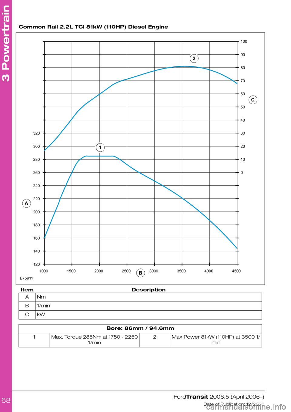
Common Rail 2.2L TCI 81kW (110HP) Diesel Engine
DescriptionItem
NmA
1/minB
kWC
Bore: 86mm / 94.6mm
Max.Power 81kW (110HP) at 3500 1/
min
2Max. Torque 285Nm at 1750 - 2250
1/min
1
FordTransit 2006.5 (April 2006–)
Date of Publication: 12/2006
3 Powertrain
68120140160180200220240260280300320100015002000250030003500400045000102030405060708090100ACB12E75911
Page 69 of 234
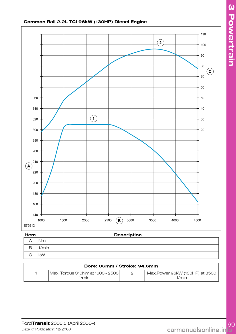
Common Rail 2.2L TCI 96kW (130HP) Diesel Engine
DescriptionItem
NmA
1/minB
kWC
Bore: 86mm / Stroke: 94.6mm
Max.Power 96kW (130HP) at 3500
1/min
2Max. Torque 310Nm at 1600 - 2500
1/min
1
FordTransit 2006.5 (April 2006–)
Date of Publication: 12/2006
3 Powertrain
69140160180200220240260280300320340360100015002000250030003500400045002030405060708090100110A12BCE75912
Page 70 of 234
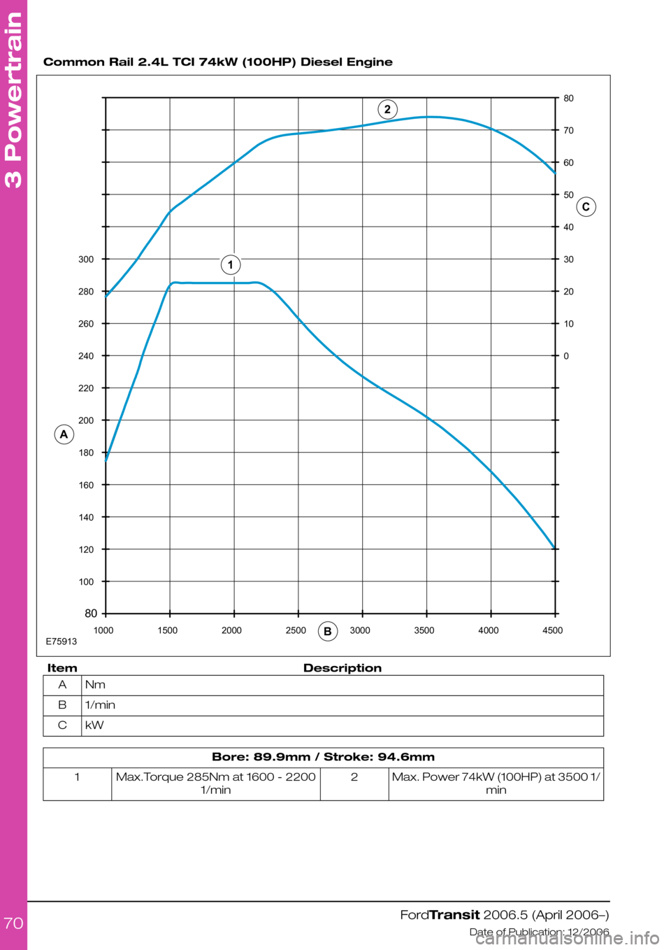
Common Rail 2.4L TCI 74kW (100HP) Diesel Engine
DescriptionItem
NmA
1/minB
kWC
Bore: 89.9mm / Stroke: 94.6mm
Max. Power 74kW (100HP) at 3500 1/
min
2Max.Torque 285Nm at 1600 - 2200
1/min
1
FordTransit 2006.5 (April 2006–)
Date of Publication: 12/2006
3 Powertrain
70801001201401601802002202402602803001000150020002500300035004000450001020304050607080A12BCE75913
Page 71 of 234
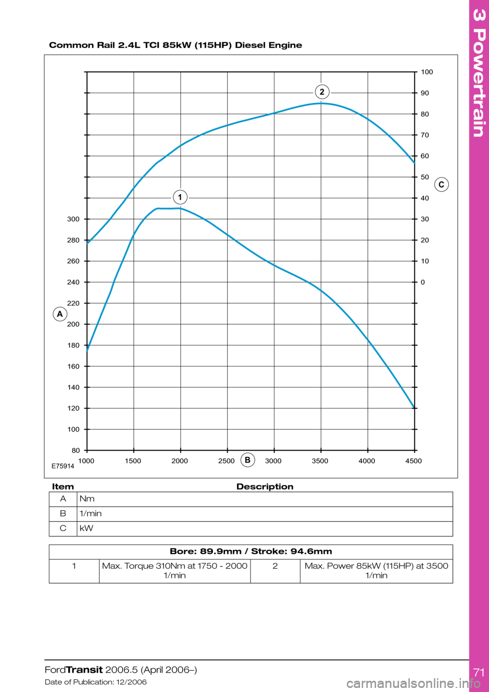
Common Rail 2.4L TCI 85kW (115HP) Diesel Engine
DescriptionItem
NmA
1/minB
kWC
Bore: 89.9mm / Stroke: 94.6mm
Max. Power 85kW (115HP) at 3500
1/min
2Max. Torque 310Nm at 1750 - 2000
1/min
1
FordTransit 2006.5 (April 2006–)
Date of Publication: 12/2006
3 Powertrain
7180100120140160180200220240260280300100015002000250030003500400045000102030405060708090100ABC21E75914
Page 72 of 234
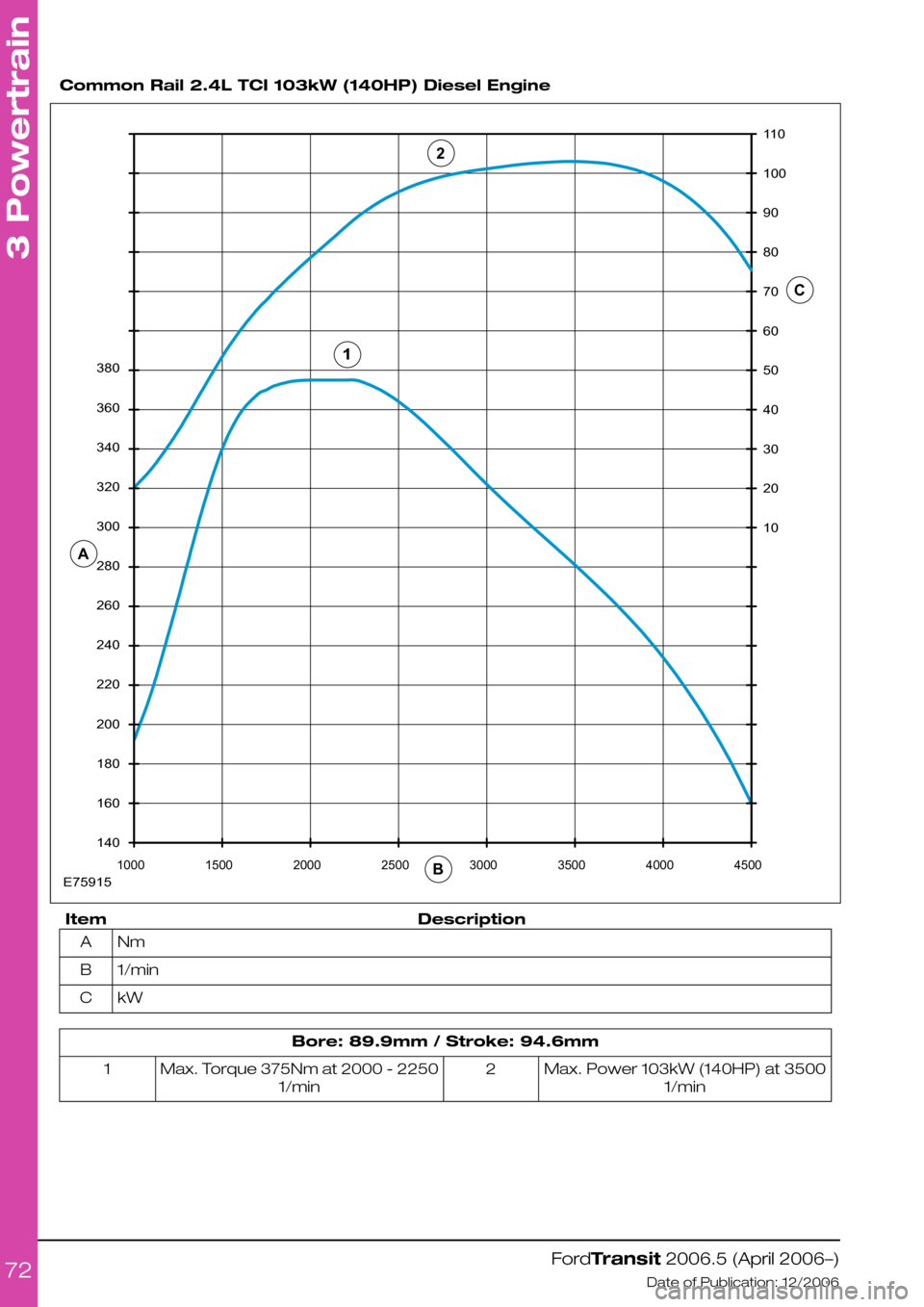
Common Rail 2.4L TCI 103kW (140HP) Diesel Engine
DescriptionItem
NmA
1/minB
kWC
Bore: 89.9mm / Stroke: 94.6mm
Max. Power 103kW (140HP) at 3500
1/min
2Max. Torque 375Nm at 2000 - 2250
1/min
1
FordTransit 2006.5 (April 2006–)
Date of Publication: 12/2006
3 Powertrain
7214016018020022024026028030032034036038010001500200025003000350040004500102030405060708090100110ABC12E75915
Page 73 of 234
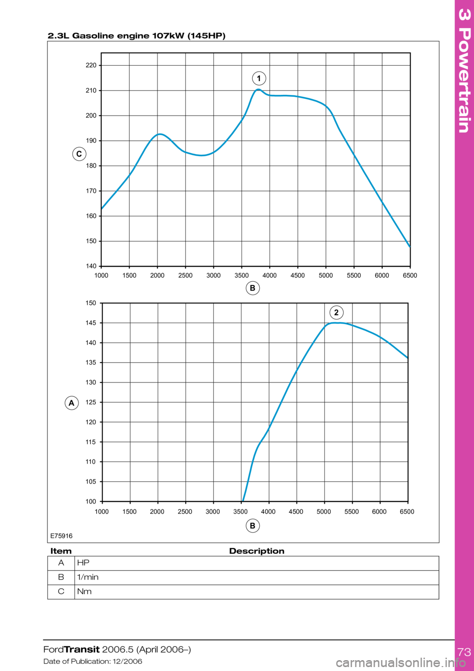
2.3L Gasoline engine 107kW (145HP)
DescriptionItem
HPA
1/minB
NmC
FordTransit 2006.5 (April 2006–)
Date of Publication: 12/2006
3 Powertrain
731401501601701801902002102201000150020002500300035004000450050005500600065001001051101151201251301351401451501000E7591615002000250030003500400045005000550060006500ACBB12
Page 75 of 234
3.2 Engine Cooling
3.2.1 Auxiliary Heater Systems
WARNINGS:
Ford coolant additives are
necessary for the complete function
of the system. Only use ford
approved or equivalent specification
component, to withstand any
detrimental effects on the materials.
Do not mount components in front
of the grille or in an area of air flow
around the engine, which could
affect the engine cooling.
CAUTIONS:
Only make connections into the
heater hose between the front cab
heater and water pump return inlet.
Do not exceed the vehicle's original
coolant volume by more than 10%
Only use the manufactures
recommended (or equivalent
specification) coolant
additives/anti-freeze. Do not mix
coolant types.
•Coolant flow to cab heater must have priority
over flow to auxiliary heater or hand wash
facility.
•Coolant tube routing must be below the base
of the degas bottle.
•Use aluminum or plastic tee junction with
swaged or beaded ends to prevent hose blow
off. Reconnect original coolant tube as shown
in view E74570 (in this section) with standard
Ford water hose clip or suitable equivalent
specification clip. Ensure interference fit
between hose and 'T' joint.
•Tube routing must be secured to the body
structure or suitable brackets avoiding
electrical components or wires, hot or moving
parts and brake or fuel system components
•Hose must be heat sleeved with appropriate
material if within 100mm of exhaust
components (for example, manifold or
exhaust gas recirculating).
•The vertical clearance between the critical
cooling components (radiator, fan shroud and
radiator brackets) and both the hood inner
and outer (assembly) panels at design position
shall not be less than 15mm.
•There shall be a minimum clearance of 7mm
between the engine assembly and flexible
components (for example, hoses or wiring
harnesses) affixed to front end sheet metal
hardware, under a maximum engine torque
roll condition.
NOTE: For further information please contact
your local National Sales Company
representative, or Local Ford Dealer. If they are
unable to help you then please contact the
Vehicle Converter Advisory service at
[email protected].
FordTransit 2006.5 (April 2006–)
Date of Publication: 12/2006
3 Powertrain
75