engine FORD TRANSIT 2006 7.G Body And Equipment Mounting Section Manual
[x] Cancel search | Manufacturer: FORD, Model Year: 2006, Model line: TRANSIT, Model: FORD TRANSIT 2006 7.GPages: 234, PDF Size: 33.19 MB
Page 76 of 234
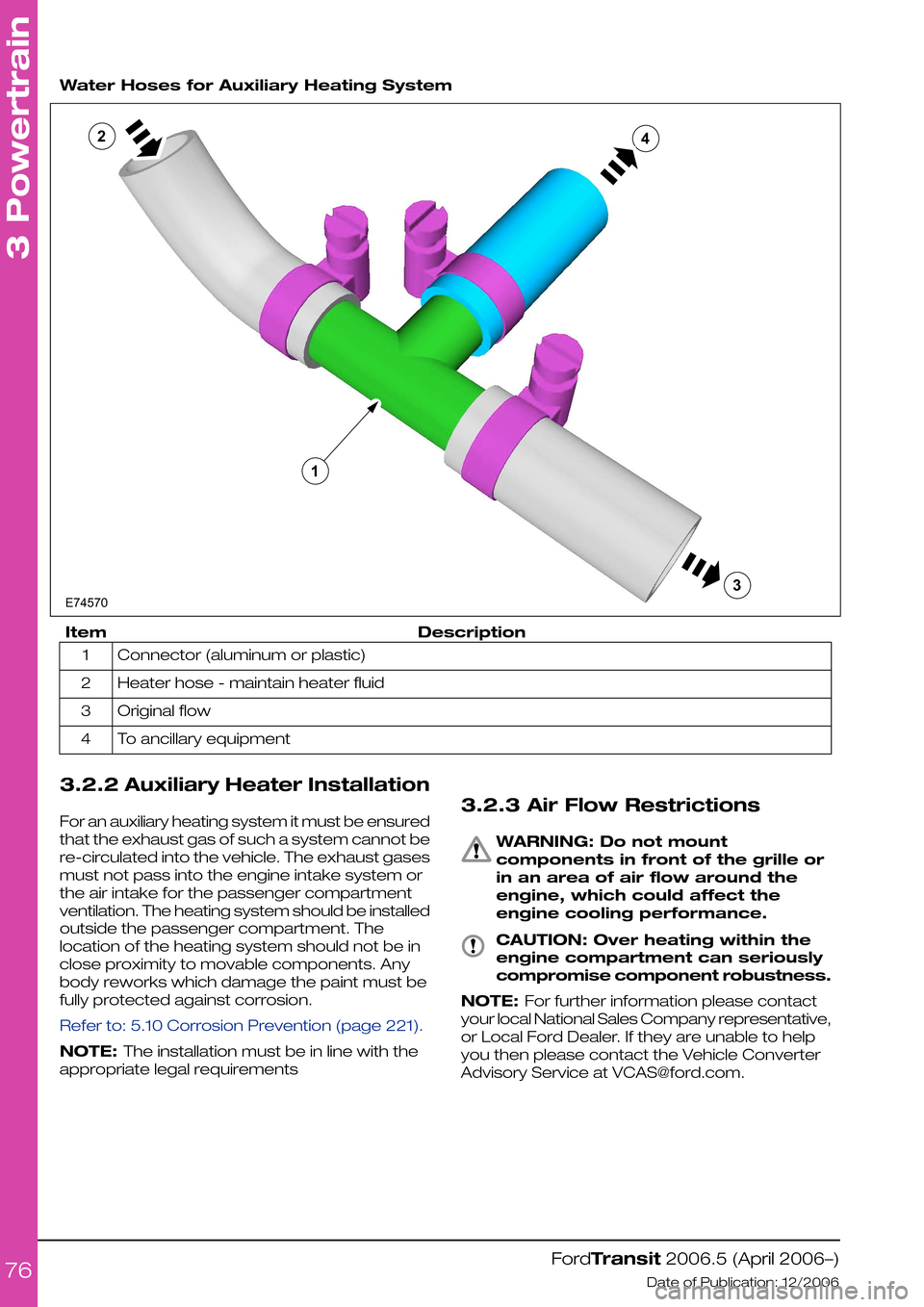
Water Hoses for Auxiliary Heating System
DescriptionItem
Connector (aluminum or plastic)1
Heater hose - maintain heater fluid2
Original flow3
To ancillary equipment4
3.2.2 Auxiliary Heater Installation
For an auxiliary heating system it must be ensured
that the exhaust gas of such a system cannot be
re-circulated into the vehicle. The exhaust gases
must not pass into the engine intake system or
the air intake for the passenger compartment
ventilation. The heating system should be installed
outside the passenger compartment. The
location of the heating system should not be in
close proximity to movable components. Any
body reworks which damage the paint must be
fully protected against corrosion.
Refer to: 5.10 Corrosion Prevention (page 221).
NOTE: The installation must be in line with the
appropriate legal requirements
3.2.3 Air Flow Restrictions
WARNING: Do not mount
components in front of the grille or
in an area of air flow around the
engine, which could affect the
engine cooling performance.
CAUTION: Over heating within the
engine compartment can seriously
compromise component robustness.
NOTE: For further information please contact
your local National Sales Company representative,
or Local Ford Dealer. If they are unable to help
you then please contact the Vehicle Converter
Advisory Service at [email protected].
FordTransit 2006.5 (April 2006–)
Date of Publication: 12/2006
3 Powertrain
76E745701234
Page 77 of 234
3.3 Accessory Drive
When the correct belt is used, tensioning is and
remains fully automatic for the life of the belt.
CAUTIONS:
Only use the manufacturers
recommended (or equivalent
specification) components
Make sure that the ancillary pulley
diameter is less than the crankshaft
pulley diameter.
Systems requiring a unique belt
NOTE: For further information please contact
your local National Sales Company
representative, or Local Ford Dealer. If they are
unable to help you then please contact the
Vehicle Converter Advisory Service at
[email protected].
The eigenfrequency of any bracket including the
auxiliary added should be above the maximum
excitation frequency of the main excitation order
of the individual engine at engine top speed. On
4-cylinder inline engines, this is the second
engine order.
3.3.1 Front End Accessory Drive
2.4l Diesel and 2.3l Petrol
CAUTION: Do not fit an additional
front end accessory drive to a
vehicle already equipped with and
air-conditioning compressor.
When engineering and installing a new front end
accessory drive, i.e. belt drive of the crankshaft
pulley, the longitudinal alignment must be within
+/- 0.25mm and angular within +/- 0.33°.
For most front end accessory drive applications
the longer Regular Production Option air
-conditioning belt can replace the standard belt
and pulley layout.
The maximum power that is available for front
end accessory drive applications, in lieu of the
air conditioning compressor is 26Nm torque at
any engine speed up to a maximum of 6kW.
FordTransit 2006.5 (April 2006–)
Date of Publication: 12/2006
3 Powertrain
77
Page 78 of 234
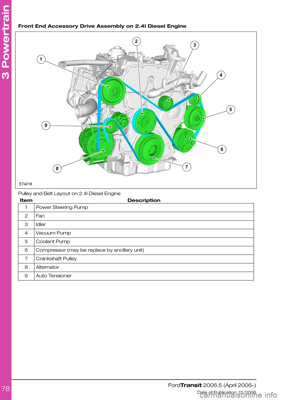
Front End Accessory Drive Assembly on 2.4l Diesel Engine
Pulley and Belt Layout on 2.4l Diesel Engine
DescriptionItem
Power Steering Pump1
Fan2
Idler3
Vacuum Pump4
Coolant Pump5
Compressor (may be replace by ancillary unit)6
Crankshaft Pulley7
Alternator8
Auto Tensioner9
FordTransit 2006.5 (April 2006–)
Date of Publication: 12/2006
3 Powertrain
78123456789E74218
Page 79 of 234
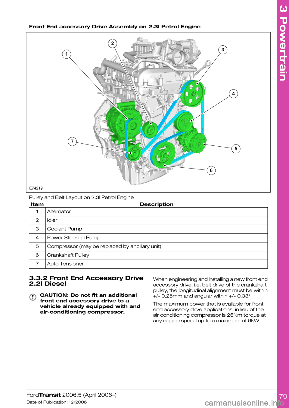
Front End accessory Drive Assembly on 2.3l Petrol Engine
Pulley and Belt Layout on 2.3l Petrol Engine
DescriptionItem
Alternator1
Idler2
Coolant Pump3
Power Steering Pump4
Compressor (may be replaced by ancillary unit)5
Crankshaft Pulley6
Auto Tensioner7
3.3.2 Front End Accessory Drive
2.2l Diesel
CAUTION: Do not fit an additional
front end accessory drive to a
vehicle already equipped with and
air-conditioning compressor.
When engineering and installing a new front end
accessory drive, i.e. belt drive of the crankshaft
pulley, the longitudinal alignment must be within
+/- 0.25mm and angular within +/- 0.33°.
The maximum power that is available for front
end accessory drive applications, in lieu of the
air conditioning compressor is 26Nm torque at
any engine speed up to a maximum of 6kW.
FordTransit 2006.5 (April 2006–)
Date of Publication: 12/2006
3 Powertrain
79E742191234567
Page 80 of 234
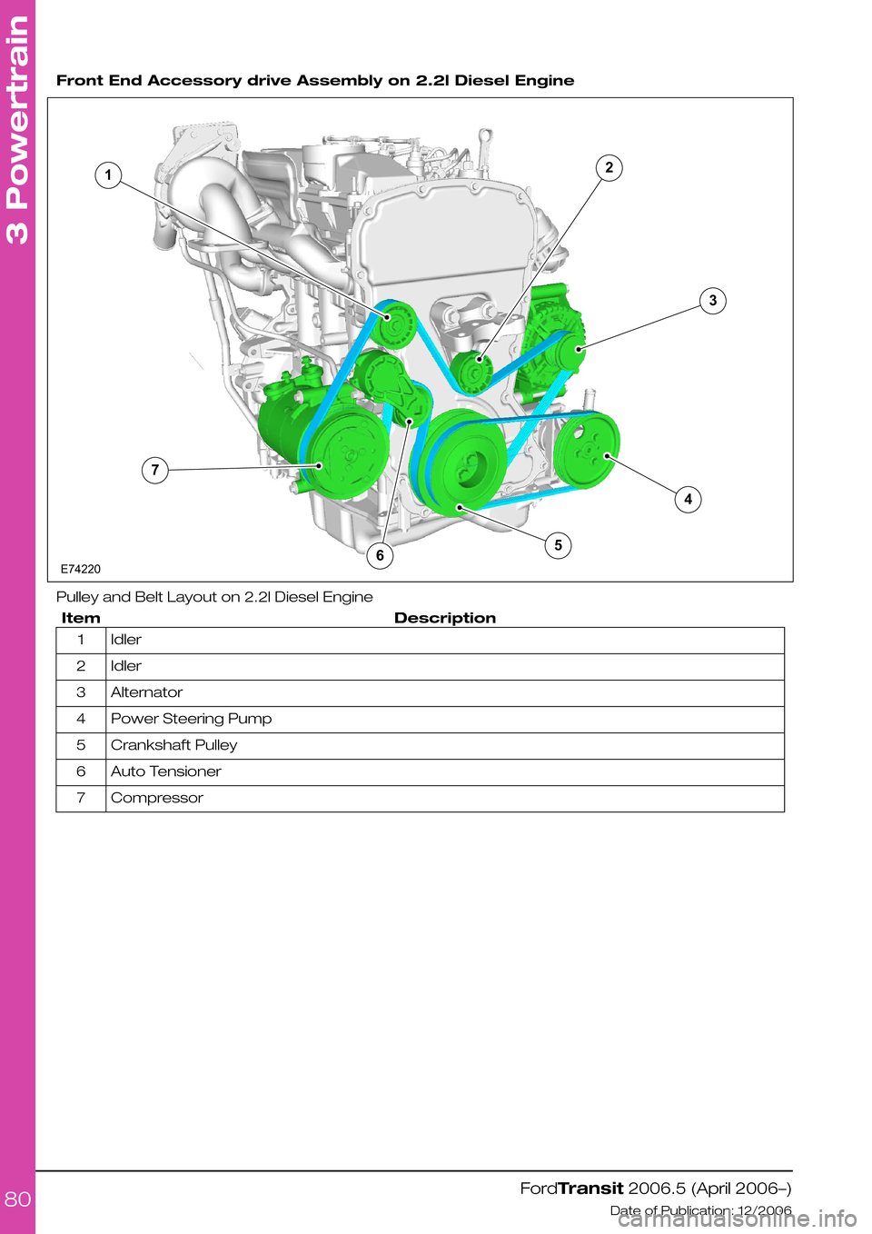
Front End Accessory drive Assembly on 2.2l Diesel Engine
Pulley and Belt Layout on 2.2l Diesel Engine
DescriptionItem
Idler1
Idler2
Alternator3
Power Steering Pump4
Crankshaft Pulley5
Auto Tensioner6
Compressor7
FordTransit 2006.5 (April 2006–)
Date of Publication: 12/2006
3 Powertrain
807123456E74220
Page 81 of 234
3.4 Electronic Engine Controls
CAUTION: Do not make any
additional connections to the
electrical circuits associated with
the engine management system
NOTE: It is not necessary to disconnect or
remove engine management modules.
FordTransit 2006.5 (April 2006–)
Date of Publication: 12/2006
3 Powertrain
81
Page 82 of 234
3.5 Clutch
The manufacturer does not offer the option of a
reinforced clutch system. The axle ratio available
is dependent on the weight of the specified donor
vehicle.
It is necessary to select the appropriate drive,
engine, gear ratio, gross vehicle mass, gross train
mass, axle plates and payloads of the base
vehicle to match the customers order.
Where possible make sure that the base vehicle
is ordered with plant fit options
NOTE: For further information please contact
your local National Sales Company representative,
or Local Ford Dealer. If they are unable to help
you then please contact the Vehicle Converter
Advisory Service at [email protected].
FordTransit 2006.5 (April 2006–)
Date of Publication: 12/2006
3 Powertrain
82
Page 83 of 234
3.6 Manual Transmission
The following manual transmissions are available
for diesel engines dependent on the drive.
•Front Wheel Drive vehicles
–VXT 75 transmission
•Rear Wheel Drive vehicles
–MT 82 transmission or
–MT 75 transmission
The following manual transmission is available
for gasoline engines .
•Rear Wheel Drive vehicles
–MT 75 transmission
WARNING: Do not reroute external
transmission gear shift cables
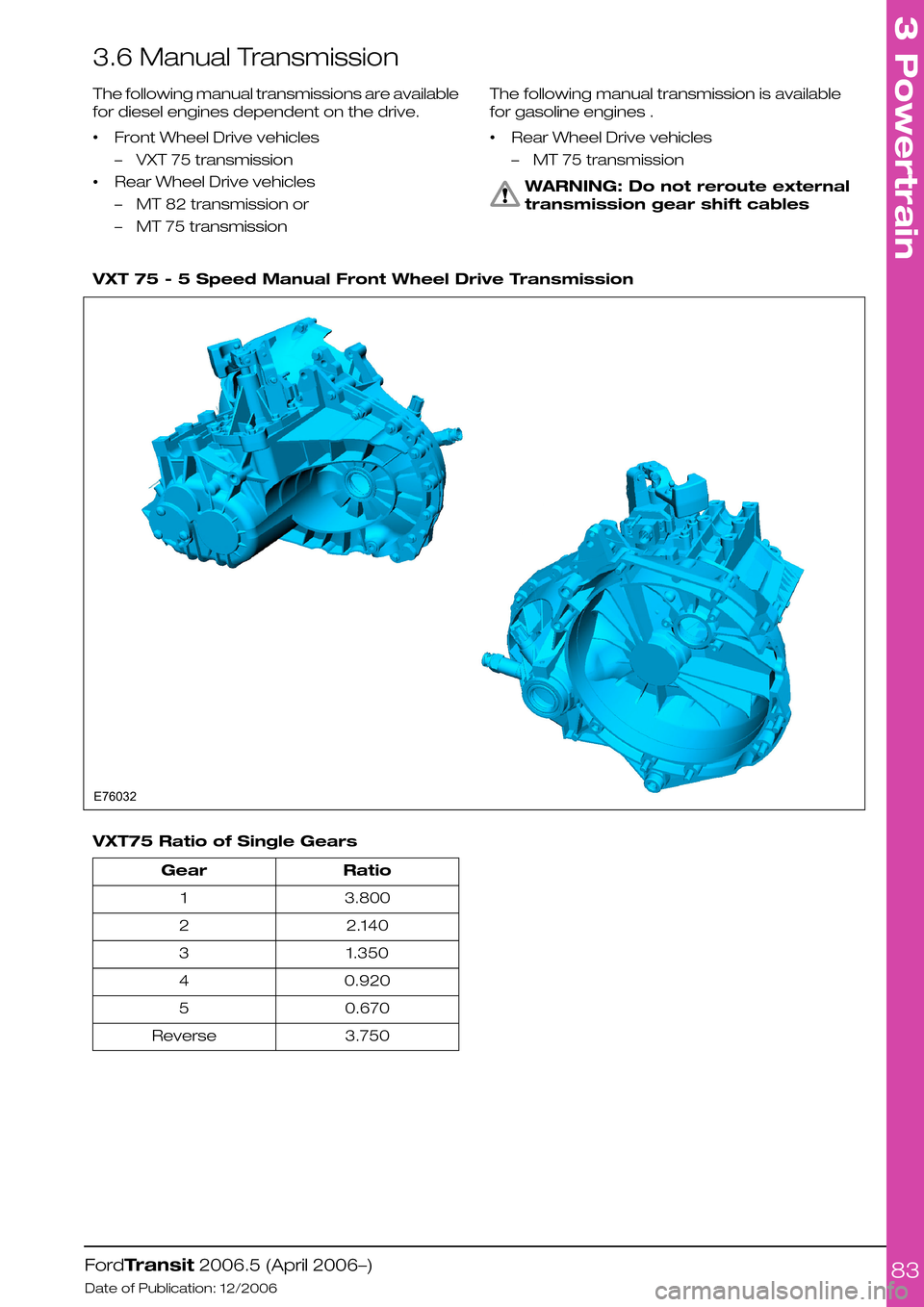
VXT 75 - 5 Speed Manual Front Wheel Drive Transmission
VXT75 Ratio of Single Gears
RatioGear
3.8001
2.1402
1.3503
0.9204
0.6705
3.750Reverse
FordTransit 2006.5 (April 2006–)
Date of Publication: 12/2006
3 Powertrain
83E76032
Page 86 of 234
3.7 Exhaust System
3.7.1 Extensions and Optional
Exhausts
CAUTIONS:
Non-standard systems must be
tested for engine back pressure and
all legal compliance (noise and
emissions)
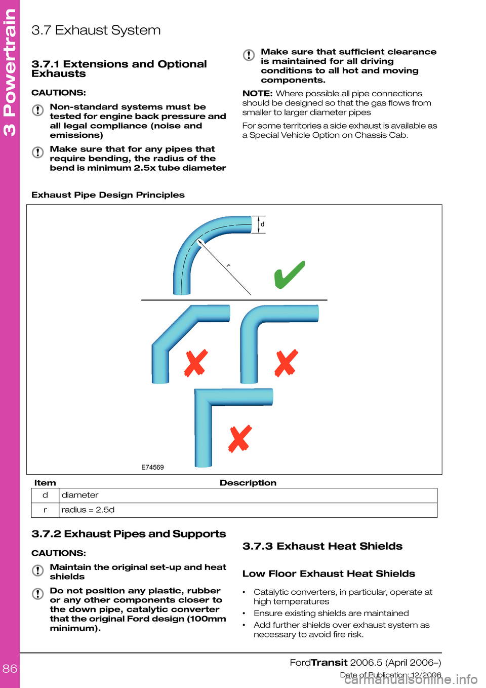
Make sure that for any pipes that
require bending, the radius of the
bend is minimum 2.5x tube diameter
Make sure that sufficient clearance
is maintained for all driving
conditions to all hot and moving
components.
NOTE: Where possible all pipe connections
should be designed so that the gas flows from
smaller to larger diameter pipes
For some territories a side exhaust is available as
a Special Vehicle Option on Chassis Cab.
Exhaust Pipe Design Principles
DescriptionItem
diameterd
radius = 2.5dr
3.7.2 Exhaust Pipes and Supports
CAUTIONS:
Maintain the original set-up and heat
shields
Do not position any plastic, rubber
or any other components closer to
the down pipe, catalytic converter
that the original Ford design (100mm
minimum).
3.7.3 Exhaust Heat Shields
Low Floor Exhaust Heat Shields
•Catalytic converters, in particular, operate at
high temperatures
•Ensure existing shields are maintained
•Add further shields over exhaust system as
necessary to avoid fire risk.
FordTransit 2006.5 (April 2006–)
Date of Publication: 12/2006
3 Powertrain
86E74569rd
Page 95 of 234
4.3 Charging System
4.3.1 General Information and
Specific Warnings
The Transit electrical system is a 12-Volt supply
with a negative earth return. The alternator and
battery equipment used as standard are
designed for normal operations with the type of
engine fitted. Higher capacity batteries are
available as standard production options and
special vehicle options. Before installing additional
electrical equipment check that the battery
capacity, harness load capability, and alternator
output are suitable for the extra load.
The battery capacity and charge available from
the alternator must be adequate to ensure
engine cranking in unfavorable climatic conditions
but excessive battery capacity could damage
the starter motor.
The Transit utilizes multiplexed vehicle electronics
- it is recommended that the appropriate Ford
proprietary accessory systems are used.
Inappropriate or incorrect connection of
additional equipment could cause mis-operation,
or damage to the vehicle, and so invalidate any
warranty.
Additional connection points are provided
specifically for customer use (except M1 and M2
Bus), and are located on the outside of the
driver's seat base.
Do not jump-start the vehicle directly from the
battery. Use designated jump-start points. Refer
to the owners literature.
4.3.2 Power Management
Settings
There are four Power Management Settings
available:
•Factory
•Transport
•Normal
•Crash
Factory and Transport modes are only active
with ignition off; with ignition on, the vehicle
operates with full functionality. When in Transport
mode, the interior lights, clocks, and power
locking and alarms (where fitted) do not work.
It is possible to switch from Transport Mode to
Normal Mode without the use of any ancillary
equipment, but not vice versa. To change mode,
the brake pedal must be depressed five times,
and the hazard warning switch operated twice
(in any combination) within 10 seconds.
WARNING: It is not possible to return
the transport setting without using
the vehicle's diagnostics.
At the end of production, the vehicle is
configured to the transport setting to minimize
power consumption. As part of the Pre Delivery
Inspection process at the Ford dealership, the
vehicle is reconfigured to normal operation.
4.3.3 Electrical Conversions
Operator requirements for additional and
specialised electrical equipment varies. The
vehicle converter/modifier must, therefore,
consider the following points when designing the
installation:
•Legality and regulatory conformity of the base
vehicle.
•Drive-ability and serviceability of the base
vehicle.
•The effect of regulations governing the
proposed conversion including National
Legislation in the country of sale.
•The method of integrating the circuit into the
base vehicle.
•No additional circuits are to be run alongside
the electrical circuits (shown in blue in the
figure below) associated with the
Management System (shown in green in the
figure below), due to the possible Electro
Motive Force (EMF) effect on the circuits.
FordTransit 2006.5 (April 2006–)
Date of Publication: 12/2006
4 Electrical
95