light GEELY CK 2008 User Guide
[x] Cancel search | Manufacturer: GEELY, Model Year: 2008, Model line: CK, Model: GEELY CK 2008Pages: 392, PDF Size: 38.86 MB
Page 150 of 392
143Section 4 Vacuum Booster with Brake Master Cylinder AssemblyNotice: The vacuum booster with brake master cylinder assembly must be repaired by
manufacturer. Replace it if it is faulty.On-vehicle inspection1. Check vacuum booster
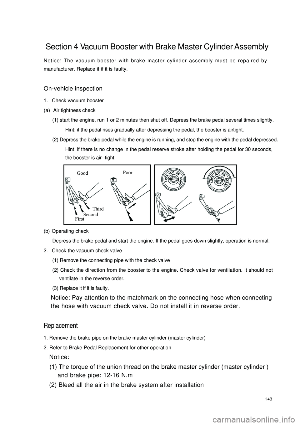
(a) Air tightness check
(1) start the engine, run 1 or 2 minutes then shut off. Depress the brake pedal several times slightly.
Hint: if the pedal rises gradually after depressing the pedal, the booster is airtight.
(2) Depress the brake pedal while the engine is running, and stop the engine with the pedal depressed.
Hint: if there is no change in the pedal reserve stroke after holding the pedal for 30 seconds,
the booster is air--tight.
(b) Operating check
Depress the brake pedal and start the engine. If the pedal goes down slightly, operation is normal.
2. Check the vacuum check valve
(1) Remove the connecting pipe with the check valve
(2) Check the direction from the booster to the engine. Check valve for ventilation. It should not
ventilate in the reverse order.
(3) Replace it if it is faulty.
Notice: Pay attention to the matchmark on the connecting hose when connecting
the hose with vacuum check valve. Do not install it in reverse order.Replacement1. Remove the brake pipe on the brake master cylinder (master cylinder)
2. Refer to Brake Pedal Replacement for other operation
Notice:
(1) The torque of the union thread on the brake master cylinder (master cylinder )
and brake pipe: 12-16 N.m
(2) Bleed all the air in the brake system after installationGoodPoorThird
Second
First
Page 171 of 392

164Section 2 Charging System
(MR479Q, MR479QA, MR481QA)I. BATTERYMaintenance-free battery is applied in this vehicle. Its termination voltage is 12V. It is connected inline by six
2V single cell in tandem with walls between every pole.
1. BATTERY WARNING SIGNS
1 -- Danger of corrosion
The battery electrolyte is very corrosive. DO NOT overturn the battery.
2 -- Read the instructions for battery
3 -- Children are forbidden to touch the battery
4 -- Avoid fire, electromagnetic wave and strong light.
Avoid electric spark while repair; avoid short.
5 -- Wear protecting glasses
6 -- Danger of explosion
The explosive mixed gas will be produced while charging.
7 -- How to deal with a scrapped battery
The scrapped battery should be delivered to the collection station.1234567
Page 173 of 392
166II. CHARGING SYSTEM INSPECTION1. CHECK BATTERY WORKING VOLTAGE
(a) After having driven the vehicle and in the case that 20 minutes have not passed after having stopped the
engine, turn the ignition switch ON and turn on the electrical system (headlight, blower motor) for 60
seconds to remove the surface charge.
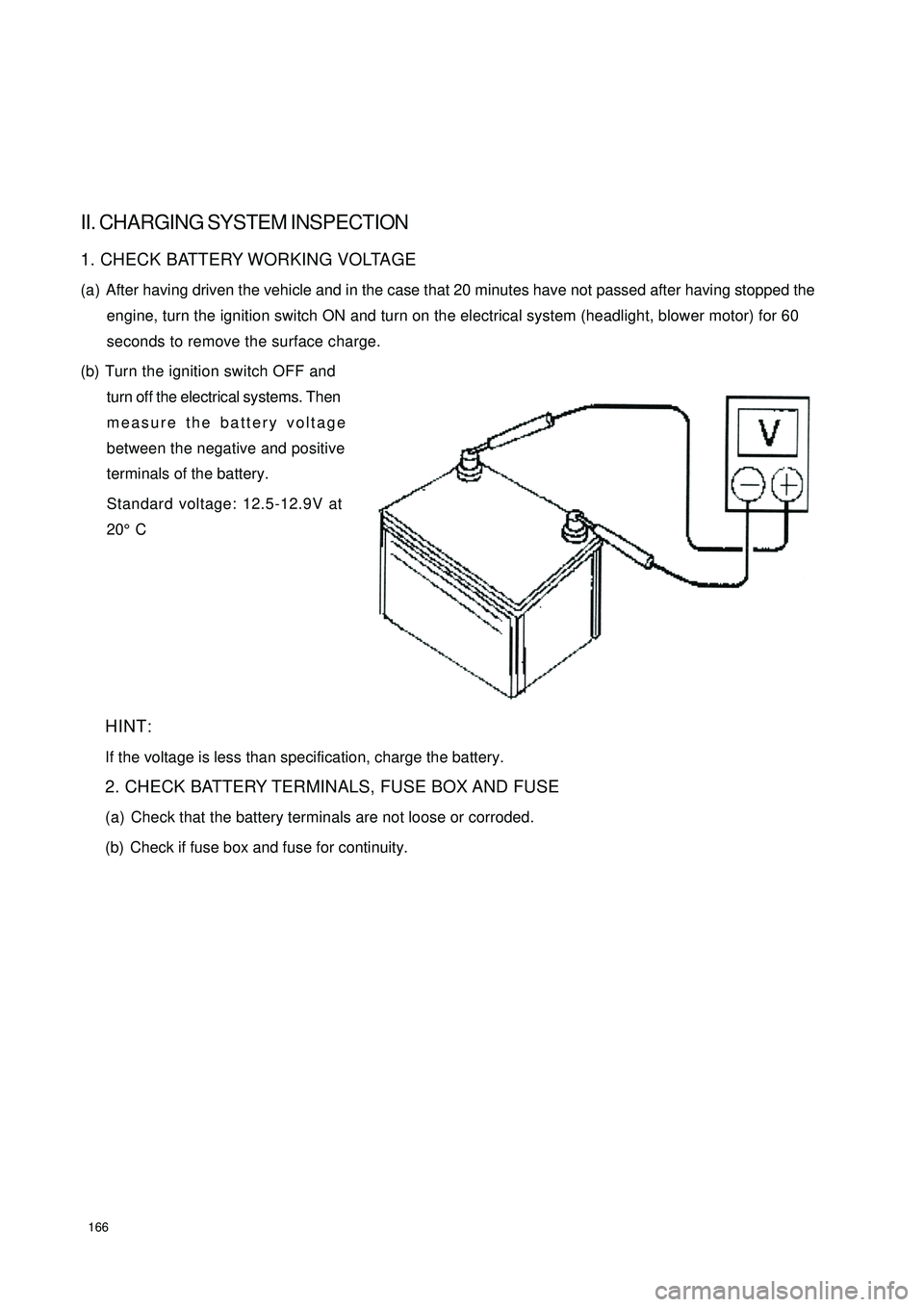
(b) Turn the ignition switch OFF and
turn off the electrical systems. Then
measure the battery voltage
between the negative and positive
terminals of the battery.
Standard voltage: 12.5-12.9V at
20°C
HINT:
If the voltage is less than specification, charge the battery.
2. CHECK BATTERY TERMINALS, FUSE BOX AND FUSE
(a) Check that the battery terminals are not loose or corroded.
(b) Check if fuse box and fuse for continuity.
Page 174 of 392
1673. INSPECT DRIVE BELT
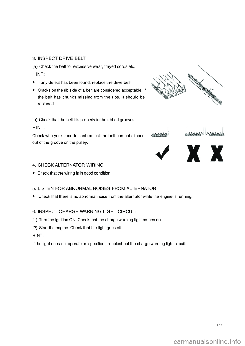
(a) Check the belt for excessive wear, frayed cords etc.
HINT:
�yIf any defect has been found, replace the drive belt.
�yCracks on the rib side of a belt are considered acceptable. If
the belt has chunks missing from the ribs, it should be
replaced.
(b) Check that the belt fits properly in the ribbed grooves.
HINT:
Check with your hand to confirm that the belt has not slipped
out of the groove on the pulley.
4. CHECK ALTERNATOR WIRING
�yCheck that the wiring is in good condition.
5. LISTEN FOR ABNORMAL NOISES FROM ALTERNATOR
�y Check that there is no abnormal noise from the alternator while the engine is running.
6. INSPECT CHARGE WARNING LIGHT CIRCUIT
(1) Turn the ignition ON. Check that the charge warning light comes on.
(2) Start the engine. Check that the light goes off.
HINT:
If the light does not operate as specified, troubleshoot the charge warning light circuit.
Page 175 of 392
1687. INSPECT CHARGING CIRCUIT WITHOUT LOAD
(a) If a battery/starter tester is
available, connect the tester to the
charging circuit as per instructions.
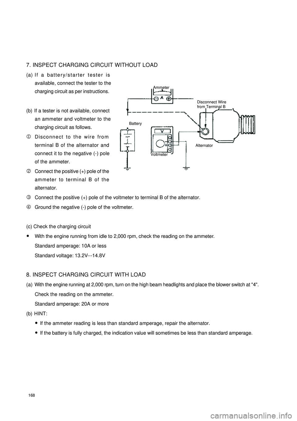
(b) If a tester is not available, connect
an ammeter and voltmeter to the
charging circuit as follows.
1Disconnect to the wire from
terminal B of the alternator and
connect it to the negative (-) pole
of the ammeter.
2Connect the positive (+) pole of the
ammeter to terminal B of the
alternator.
3Connect the positive (+) pole of the voltmeter to terminal B of the alternator.
4Ground the negative (-) pole of the voltmeter.
(c) Check the charging circuit
�yWith the engine running from idle to 2,000 rpm, check the reading on the ammeter.
Standard amperage: 10A or less
Standard voltage: 13.2V---14.8V
8. INSPECT CHARGING CIRCUIT WITH LOAD
(a) With the engine running at 2,000 rpm, turn on the high beam headlights and place the blower switch at "4".
Check the reading on the ammeter.
Standard amperage: 20A or more
(b) HINT:
�yIf the ammeter reading is less than standard amperage, repair the alternator.
�yIf the battery is fully charged, the indication value will sometimes be less than standard amperage.Ammeter
Disconnect Wire
from Terminal B
Battery
VoltmeterAlternator
Page 178 of 392

171Chapter 3 Combination Meter SystemSection 1 Circuit Diagram of Combination Meter and Location of
Multi-pin Plug-in TerminalI. CIRCUIT DIAGRAM OF CONBINATION METERSpeed Signal
Ground The Sensor
Revolution SignalWater Temperature SignaFuel Level GaugeTachometer
SpeedometerWater
Temperature Gauge
Feul Level Gauge
OdometerHigh Beam Lamp
Rear Defrost Lamp
Rear Defog Lamp
Backlight
Water Temperature WarningPower Steering
Fuel WarningCharge
Brake Fluid
Oil Pressure
Engine Malfunction
Driver's seat belt
Park Brake
SRS(main)
SRS(sub)
Page 179 of 392

172II. LOCATION OF HARHESS MULTI-PIN PLUG-IN TERMINAL(1) HINT:
R -- RE Bl -- BLUE Y -- YELLOW
B -- BLACK P -- PIN G -- GREEN
W -- WHITE O -- ORANGE Gr -- GRAY
Br -- BROWN V -- VIOLETL g -- LIGHT GREEN
The first letter represents the base color
The second letter represents the color of the stripe
e.g. VG (violet & green) V-violet, G-greenColor of connector A is white, and B is blackVG
Page 193 of 392
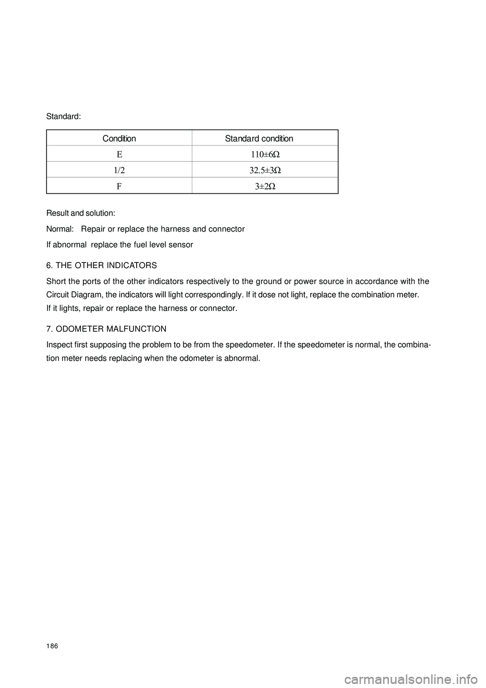
186Standard:
Result and solution:
Normal:Repair or replace the harness and connector
If abnormal replace the fuel level sensor
6. THE OTHER INDICATORS
Short the ports of the other indicators respectively to the ground or power source in accordance with the
Circuit Diagram, the indicators will light correspondingly. If it dose not light, replace the combination meter.
If it lights, repair or replace the harness or connector.
7. ODOMETER MALFUNCTION
Inspect first supposing the problem to be from the speedometer. If the speedometer is normal, the combina-
tion meter needs replacing when the odometer is abnormal.Condition Standa rd condition
E 110±6Ω
1/2 32.5±3Ω
F3±2Ω
Page 194 of 392
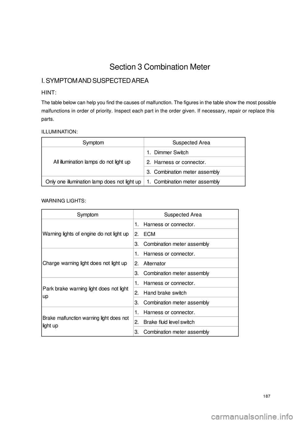
187Section 3 Combination MeterI. SYMPTOM AND SUSPECTED AREAHINT:
The table below can help you find the causes of malfunction. The figures in the table show the most possible
malfunctions in order of priority. Inspect each part in the order given. If necessary, repair or replace this
parts.
ILLUMINATION:
WARNING LIGHTS:Symptom Suspected Area
1. Dimmer Switch
2. Harness or connector.
3. Combina tion me te r a s se mbly
Only one illumina tion la mp doe s not light up 1. Combina tion me ter asse mblyA ll illumina t ion la mps do not light upSymptom Suspected Area
1. Ha rness or connec tor.
2. ECM
3. Combination me te r a sse mbly
1. Ha rness or connec tor.
2. Alterna tor
3. Combination me te r a sse mbly
1. Ha rness or connec tor.
2. Hand brake switch
3. Combination me te r a sse mbly
1. Ha rness or connec tor.
2. Bra ke fluid le ve l switc h
3. Combination me te r a sse mbly Wa rning lights of e ngine do not light up
Cha rge wa rning light doe s not light up
P a rk bra ke wa rning light does not light
upBrake malfunc tion warning light doe s notlight up
Page 195 of 392

188Symptom Suspe cte d Area
1. Ha rne ss or connec tor.
2. ABS controlle r or ABS wa rning light driver module
3. C ombina tion me te r a s s e mbly
1. Ha rne ss or connec tor.
2. SRS controller
3. C ombina tion me te r a s s e mbly
1. Ha rne ss or connec tor.
2. SRS controller
3. C ombina tion me te r a s s e mbly
1. Ha rne ss or connec tor.
2. O il pr e s s ur e s w it c h a s s e mbly
3. C ombina tion me te r a s s e mbly
1. Ha rne ss or connec tor.
2. Headlamp light control switch
3. C ombina tion me te r a s s e mbly
1. Ha rne ss or connec tor.
2. Headlamp light control switch
3. C ombina tion me te r a s s e mbly
1. Ha rne ss or connec tor.
2. Ce ntra l c ontrolle r or re a r de fros t sw itc h
3. C ombina tion me te r a s s e mbly
1. Ha rne ss or connec tor.
2. Electric Power Steering controller
3. C ombina tion me te r a s s e mbly
1. Ha rne ss or connec tor.
2. Engine c oola nt te mpe ra ture se nsor
3. C ombina tion me te r a s s e mbly
1. Ha rne ss or connec tor.
2. Se a t belt buckle switch
3. C ombina tion me te r a s s e mbly ABS warning light doe s not light up
SRS wa rning light doe s not light up
SRS (Sub) indic a tor doe s not light up
Oil pre ssure wa rning light does not light
up
Water temperature warning indicator
doe s not light up
Se at be lt wa rning indic a tor doe s not light
up High be a m indica tor does not light up
Re a r fog indica tor does not light up
Re a r defrost indic a tor doe s not light up
EP S wa rning indic ator doe s not light up