power steering GEELY CK 2008 Owner's Manual
[x] Cancel search | Manufacturer: GEELY, Model Year: 2008, Model line: CK, Model: GEELY CK 2008Pages: 392, PDF Size: 38.86 MB
Page 139 of 392

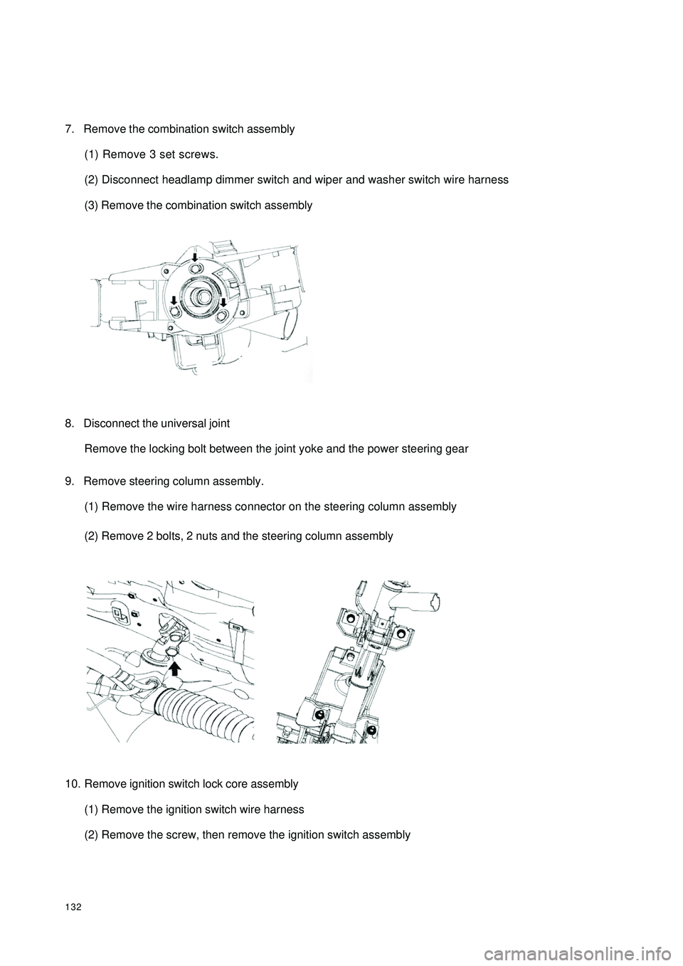
1327. Remove the combination switch assembly
(1) Remove 3 set screws.
(2) Disconnect headlamp dimmer switch and wiper and washer switch wire harness
(3) Remove the combination switch assembly
8. Disconnect the universal joint
Remove the locking bolt between the joint yoke and the power steering gear
9. Remove steering column assembly.
(1) Remove the wire harness connector on the steering column assembly
(2) Remove 2 bolts, 2 nuts and the steering column assembly
10. Remove ignition switch lock core assembly
(1) Remove the ignition switch wire harness
(2) Remove the screw, then remove the ignition switch assembly
Page 140 of 392

13311. Complete the service or replace the steering column assembly, the installation procedure is in the reverseorder of the removal
Notice:
(1) after the installation of the ignition lock core, check the steering lock operation: the
steering mechanism lock when the ignition key is pulled out; the steering mechanism
unlock when the key is inserted and turned to ACC position
(2)The torque of the 2 bolts and 2 nuts securing the steer column assembly:
16~26N.m
(3) connect the wire harness into place and make sure the wiring is good
(4) After properly adjust the positions of the combination switch and the steering column
upper and lower cover, tighten the 3 screws attaching the combination switch and the
steering column
(5) Torque of the universal joint yoke and steering gear assembly locking bolt: 22~34N.m
(6) Torque of the 4 set bolts of the dust cover and press plate: 16~26N.m
(7) When installing the steering wheel assembly, align the matchmarks of the steering wheel
and steering main shaft assembly,
Torque of the steering wheel specific inner torx bolt: 40~60N.m
(7) Check the air bag, it is not allowed to use the air bag parts from another vehicle
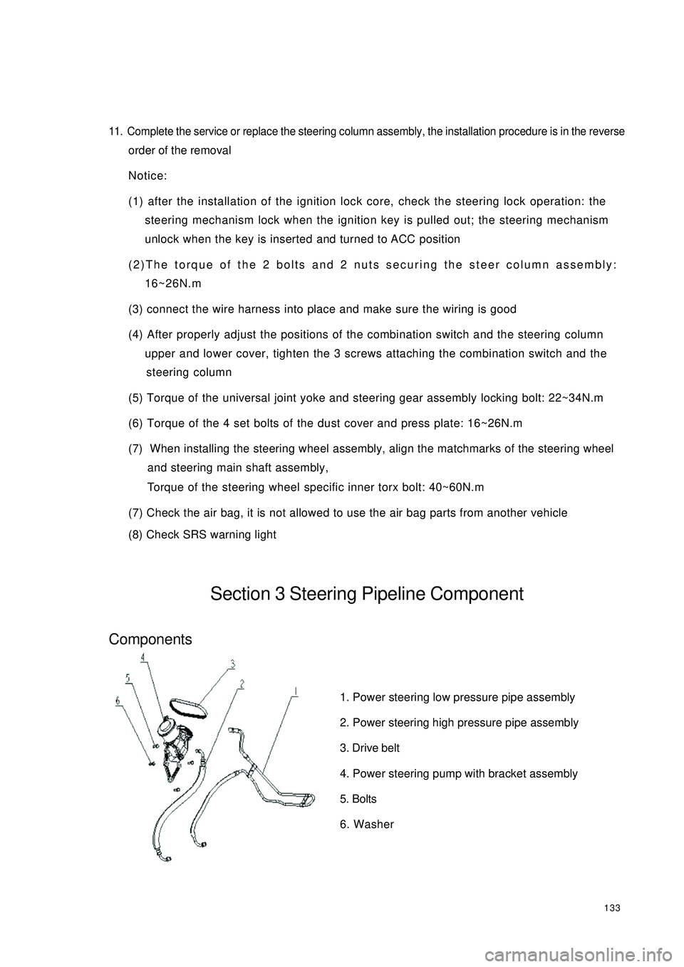
(8) Check SRS warning lightSection 3 Steering Pipeline ComponentComponents1. Power steering low pressure pipe assembly
2. Power steering high pressure pipe assembly
3. Drive belt
4. Power steering pump with bracket assembly
5. Bolts
6. Washer
Page 141 of 392

134On-vehicle inspection1. check the drive belt
Observe the drive belt for excessive wear and cordline wear. Replace the drive belt if necessary.
Hint: Cracks on the rib side of a belt are considered acceptable. If missing chunks from the
ribs are found on the drive belt, it should be replaced.
2. Bleed the power steering system
(1) Check the fluid level
(2) Jack up the front of the vehicle and make sure it is safe
(3) Rotate the steering wheel
a. With the engine off, turn the steering wheel from LH limit position to RH limit position several
times
(4) Release the jack and lower the vehicle
(5) Start the engine, run the engine at idle for a few minutes
(6) Turn the steering wheel to left or right limit position and keep it there for 2 - 3 seconds, then turn the
steering wheel to the opposite limit position and keep it there for 2 - 3 seconds. Repeat it several
times.
(7) Shut off the engine, check for foaming or emulsification in the reservoir. If there is foaming or
emulsification, bleed power steering system repeatedly
(8) Check the fluid level and for leakage
2. Check the fluid level
(1) Park the vehicle on a level surface
(2) With the engine stopped, check the fluid level in the reservoir. Add power steering fluid AT F
DEXRON if necessary.
Hint: the fluid level should be within the range of lowest level and highest level
(3) Check for foaming or emulsification, if there is, drain the power steering systemNormalAbnormal
Page 142 of 392

135Replacement1. Drain the power steering system fluid
2. Remove the power steering high and low pressure pipe
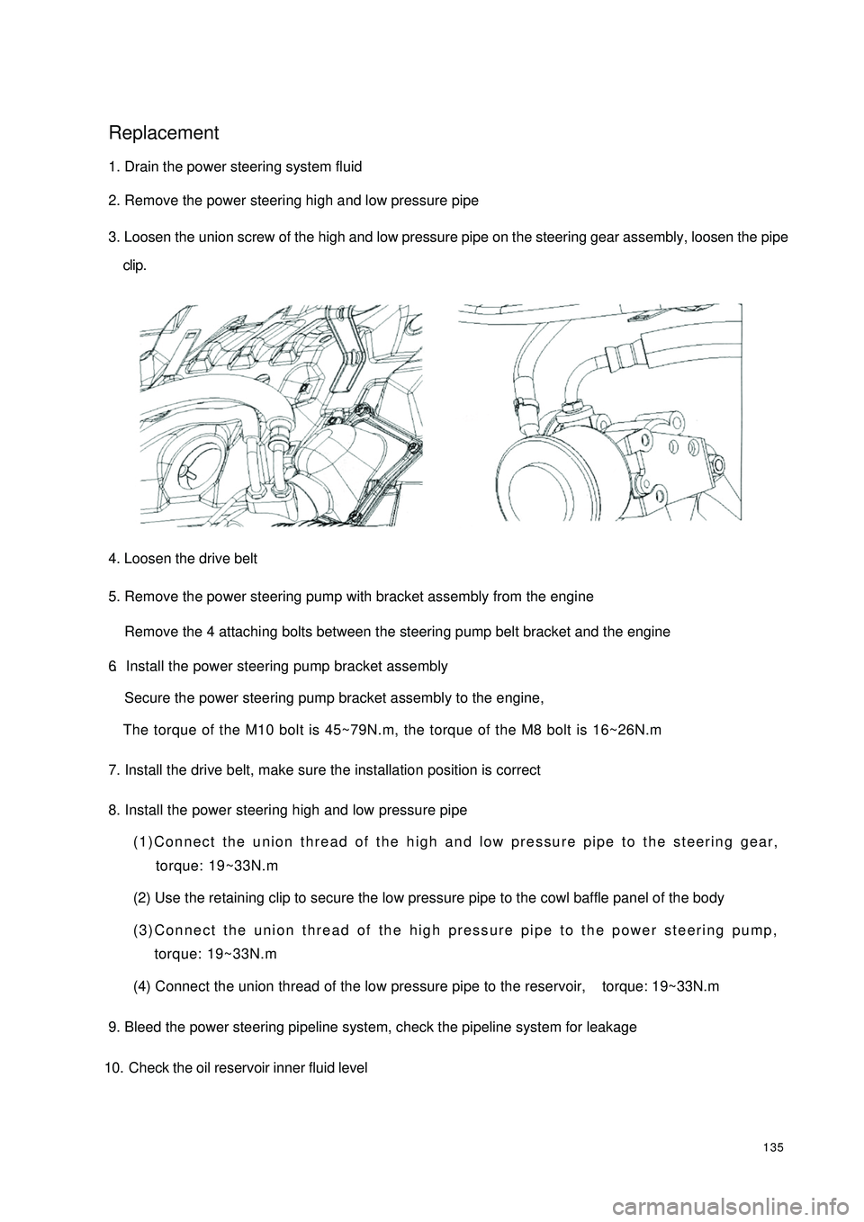
3. Loosen the union screw of the high and low pressure pipe on the steering gear assembly, loosen the pipe
clip.
4. Loosen the drive belt
5. Remove the power steering pump with bracket assembly from the engine
Remove the 4 attaching bolts between the steering pump belt bracket and the engine6.Install the power steering pump bracket assemblySecure the power steering pump bracket assembly to the engine,
The torque of the M10 bolt is 45~79N.m, the torque of the M8 bolt is 16~26N.m7. Install the drive belt, make sure the installation position is correct
8. Install the power steering high and low pressure pipe(1)Connect the union thread of the high and low pressure pipe to the steering gear,
torque: 19~33N.m
(2) Use the retaining clip to secure the low pressure pipe to the cowl baffle panel of the body
(3)Connect the union thread of the high pressure pipe to the power steering pump,
torque: 19~33N.m
(4) Connect the union thread of the low pressure pipe to the reservoir, torque: 19~33N.m
9. Bleed the power steering pipeline system, check the pipeline system for leakage
10. Check the oil reservoir inner fluid level
Page 143 of 392

136Section 4 Power Steering Gear Retaining DeviceComponentsFront Cowl Panel AssemblyCotter Pin Cotter Pin
Page 144 of 392

137Tie Rod RH Ball Stud PinLock NutWire ClipNo.1 BootBandPipeO-ringO-ringO-ringBand
Wire ClipNo. 2 BootLock NutTie Rod LH Ball Stud PinJoint Sub-assemblyJoint Sub-assemblyReplacement1. Drain the power steering system fluid
2. Separate the tie rod from the steering knuckle
(1) Remove the cotter pin, loosen the groove type lock nut
(2) Separate the tie rod ball stud joint from the steering knuckle taper hole
Page 145 of 392

1383. Loosen the union thread of the high and low pressure pipes on the steering gear assembly
4. Remove the boot band and No. 1, No. 2 boots
5. Disconnect the power steering gear assembly from the steering column
Remove the steering gear pinion shaft spline lock bolt on the universal joint yoke
6. Remove power steering gear assembly
Remove 4 steering gear assembly set bolts, remove the power steering gear assembly
7. Installation is in the reverse order of the removal
Notice:
(1) Insert the steering gear pinion shaft spline into the spline hole of the universal joint
yoke, make sure that the positions of the notch of the steering gear pinion shaft and the
lock bolt of the universal joint yoke are correct
(2) Secure the power steering gear with 4 bolts, torque: 63~93N.m
(3) Tighten the steering gear pinion shaft spline lock bolt on the universal joint yoke, torque:
22~34N.m
(4) Tighten the 4 set bolts of the boot band and boot torque: 16~26N.m
(5) Install the union thread of the power steering high and low pressure pipe to the power
steering gear, torque: 19~33N.m
(6) Connect the tie rod ball stud pin with the steering knuckle, make sure that the mating
surface of the tie rod ball stud pin and the steering knuckle is clean, tighten the slot nut,
torque: 27~39N.m. Install the cotter pin, make sure of the correct installation
(7) Add appropriate amount of specified power steering fluid, bleed the power steering sys-
tem
(8) Check the power steering pipeline system for leakage
(9) Check the front wheel alignment and front wheel left and right limit turn angle, adjust the
toe in if necessary and tighten the tie rod lock nut
(10)Check the position of the steering wheel. It is required that the steering wheel spokes
are basically symmetrical when the vehicle is driven straight ahead, reassemble the steering
wheel if necessary
Page 178 of 392

171Chapter 3 Combination Meter SystemSection 1 Circuit Diagram of Combination Meter and Location of
Multi-pin Plug-in TerminalI. CIRCUIT DIAGRAM OF CONBINATION METERSpeed Signal
Ground The Sensor
Revolution SignalWater Temperature SignaFuel Level GaugeTachometer
SpeedometerWater
Temperature Gauge
Feul Level Gauge
OdometerHigh Beam Lamp
Rear Defrost Lamp
Rear Defog Lamp
Backlight
Water Temperature WarningPower Steering
Fuel WarningCharge
Brake Fluid
Oil Pressure
Engine Malfunction
Driver's seat belt
Park Brake
SRS(main)
SRS(sub)
Page 195 of 392

188Symptom Suspe cte d Area
1. Ha rne ss or connec tor.
2. ABS controlle r or ABS wa rning light driver module
3. C ombina tion me te r a s s e mbly
1. Ha rne ss or connec tor.
2. SRS controller
3. C ombina tion me te r a s s e mbly
1. Ha rne ss or connec tor.
2. SRS controller
3. C ombina tion me te r a s s e mbly
1. Ha rne ss or connec tor.
2. O il pr e s s ur e s w it c h a s s e mbly
3. C ombina tion me te r a s s e mbly
1. Ha rne ss or connec tor.
2. Headlamp light control switch
3. C ombina tion me te r a s s e mbly
1. Ha rne ss or connec tor.
2. Headlamp light control switch
3. C ombina tion me te r a s s e mbly
1. Ha rne ss or connec tor.
2. Ce ntra l c ontrolle r or re a r de fros t sw itc h
3. C ombina tion me te r a s s e mbly
1. Ha rne ss or connec tor.
2. Electric Power Steering controller
3. C ombina tion me te r a s s e mbly
1. Ha rne ss or connec tor.
2. Engine c oola nt te mpe ra ture se nsor
3. C ombina tion me te r a s s e mbly
1. Ha rne ss or connec tor.
2. Se a t belt buckle switch
3. C ombina tion me te r a s s e mbly ABS warning light doe s not light up
SRS wa rning light doe s not light up
SRS (Sub) indic a tor doe s not light up
Oil pre ssure wa rning light does not light
up
Water temperature warning indicator
doe s not light up
Se at be lt wa rning indic a tor doe s not light
up High be a m indica tor does not light up
Re a r fog indica tor does not light up
Re a r defrost indic a tor doe s not light up
EP S wa rning indic ator doe s not light up
Page 204 of 392

197III. WIPER SWITCH ASSEMBLY REPLACEMENT1. DETACH STEERING WHEEL ASSEMBLY
(a) Disconnect the main power source of the vehicle.
(b) Remove the passenger SRS module assembly, and cautiously put it in a safe place.
(c) Loosen steering wheel lock-bolts and remove the assembly.
2. REMOVE WIPER SWITCH
(a) Disconnect the connector.
(b) Remove the 2 tapping screws that are for mounting the wiper switch, take out the wiper switch from the
bracket of the combination switch.IV. WASHER NOZZLEADJUSTMENT
1. INSPECT WASHER NOZZLE
(a) Start the engine, check if the position where the washer fluid from the nozzle sprays the windshield is in
the central or upper of the area wiped by the blades.
(b) Change the direction (horizontal) of the nozzle hole to adjust the point where washer fluid sprays the
windshield.