sensor GEELY CK 2008 Owner's Guide
[x] Cancel search | Manufacturer: GEELY, Model Year: 2008, Model line: CK, Model: GEELY CK 2008Pages: 392, PDF Size: 38.86 MB
Page 106 of 392
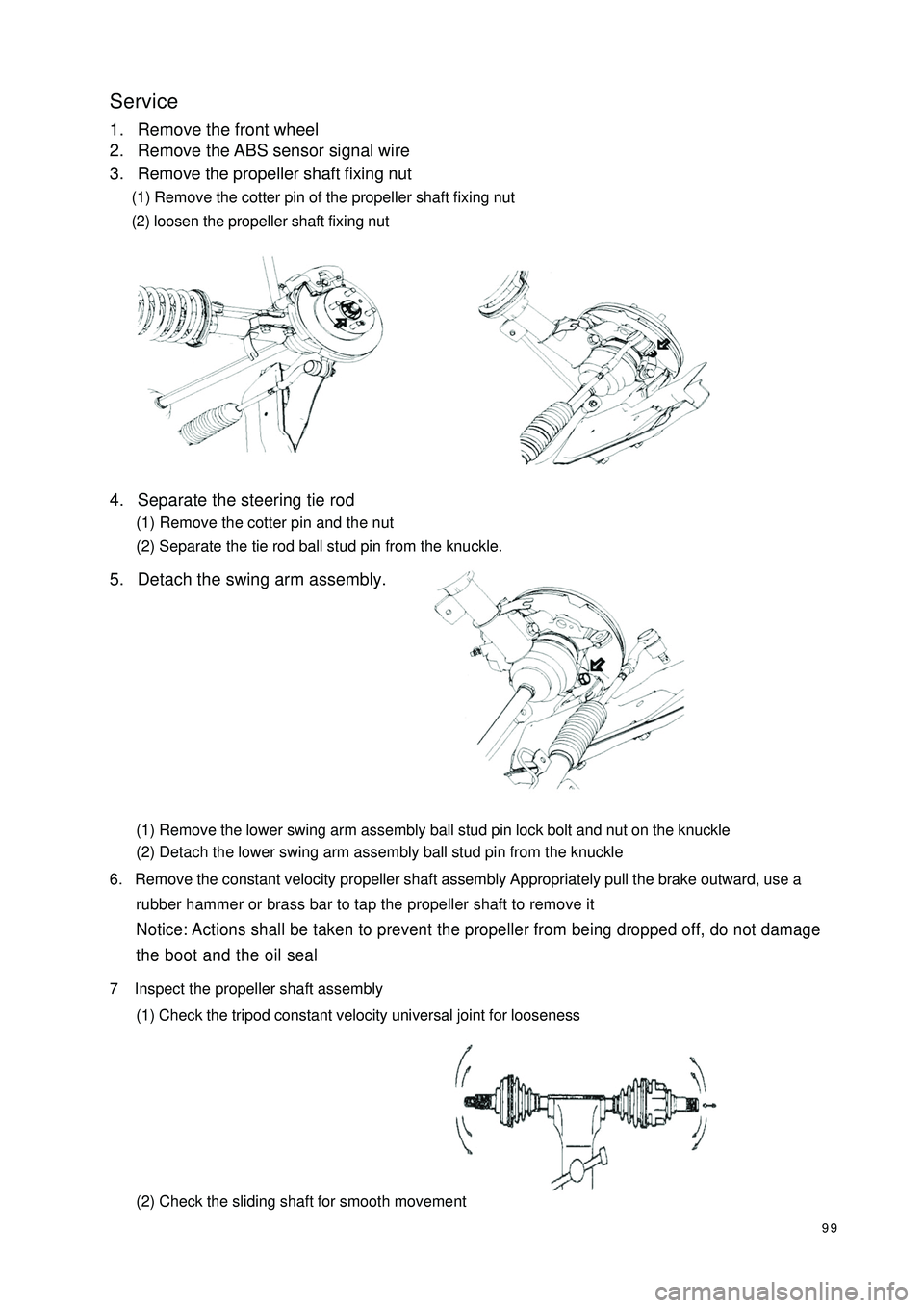
99Service1. Remove the front wheel
2. Remove the ABS sensor signal wire
3. Remove the propeller shaft fixing nut
(1) Remove the cotter pin of the propeller shaft fixing nut
(2) loosen the propeller shaft fixing nut
4. Separate the steering tie rod
(1) Remove the cotter pin and the nut
(2) Separate the tie rod ball stud pin from the knuckle.
5. Detach the swing arm assembly.
(1) Remove the lower swing arm assembly ball stud pin lock bolt and nut on the knuckle
(2) Detach the lower swing arm assembly ball stud pin from the knuckle
6. Remove the constant velocity propeller shaft assembly Appropriately pull the brake outward, use a
rubber hammer or brass bar to tap the propeller shaft to remove itNotice: Actions shall be taken to prevent the propeller from being dropped off, do not damage
the boot and the oil seal7 Inspect the propeller shaft assembly
(1) Check the tripod constant velocity universal joint for looseness
(2) Check the sliding shaft for smooth movement
Page 109 of 392
102(7) Install front wheel, wheel nut torque: 95~115N.m
(8) Make sure that the propeller shafts for 1.3L engine and 1.5L engine are not interchanged
at the time of replacement
(9) Check the ABS sensor signal, check and adjust the front wheel alignment if necessary.
Page 112 of 392

105Section 2 Front SuspensionComponents
LF Strut Assembly
Front
Brake Hose Clip
Connected to Brake
Connected
to Brake
LF Brake Assembly
Stabilizer Bar
Left Link Rod
Assembly
Left lower Swing
Arm Assembly
Lower Swing
Arm LF Bracket
Lower Swing Arm
RF Bracket
Front Stabilizer Bar Assembly
Stabilizer Bar
Right Link Rod Assembly
RF Brake Assembly
Connected to Brake
Clip
Front Brake Hose
RF Strut Assembly
Connected
to Brake
BodyBody
Right Lower
Swing Arm
Assembly
Lower Trailing
Arm Rear Elastic Hinge
Fixed to Shock
Absorber
ABS Sensor Wire Harness
Shock Absorber
Page 114 of 392

107Section 4 Front Strut AssemblyComponents:WasherMount CoverShock Absorber Mount SupportBig WasherThrust Ball BearingSpring Upper SeatFront Coil Spring
Upper InsulatorFront Coil SpringLeft Brake Assembly ABS Sensor Wire HarnessFront Brake Hose Stabilizer Bar Left
Link Rod AssemblyLF Shock Absorber AssemblyFront Coil Spring Lower InsulatorFront BumperFront Shock Absorber
Protecting Sleeve
Page 115 of 392

108Replacement1. Remove the front wheel.
2. Remove the ABS sensor from the steering knuckle. Separate the sensor and signal wire from the wire
harness bracket on the front shock absorber.
3. Separate the front brake hose
Remove 2 clips and separate the front brake hose from the front shock absorber bracket.
4. Remove the stabilizer bar link rod assembly
Remove the nut connecting the stabilizer bar link rod assembly and the shock absorber.
5. Remove the front shock absorber with the coil spring
(1) Remove the nuts and bolts connecting the shock absorber and brake.
(2) Remove the 4 nuts connecting the front shock absorber and vehicle body.
Notice: reliable object shall be used to support the brake assembly!
Page 116 of 392
1096. Disassemble the front strut assembly
(1) Remove the nut on the shock absorber.
Notice: the elasticity of the spring is recovered!
(2) Remove the washer, collar, shock absorber mount seat and big washer.
(3) Remove spring upper seat, front coil spring , front shock absorber boot, front dumper, front coil spring
lower insulator.
7. Assemble the front strut assembly
The assembly of the front strut assembly is in the reverse order of disassembly.
Notice:
(1) Use special fixture when installing the nut on the shock absorber piston rod, be
careful not to let the spring rebound. Torque: 80~90 N.Sm.(2) Install the 4 bolts attaching the front strut assembly to the body. Torque: 25~30N.m.(3) Install the 2 bolts and nuts of the front strut assembly and the brake.
Torque: 90~100N.m.
(4) Install the attaching nuts on the stabilizer bar link rod assembly and shock absorber.
Torque: 50~60N.m.
(5) Install the ABS sensor and secure the signal wire.
Page 124 of 392

117Section 2 Rear SuspensionComponents
LR Strut Assembly
LR ABS Sensor Wire Harness
LR Brake
LR Brake Pipe
Clip
Clip
RR Strut Assembly
Clip
RR ABS Sensor Wire Harness
RR Brake Hosex2
No. 2 Transverse Arm
Left Trailing Rod Assembly
Body
Body
Body Body
No. 1 Transverse Arm
No. 1 Rocker Arm
Clip
RR Brake Pipe
RR Brake Hose
RR Brake
Right Trailing Rod Assembly
Rear Stabilizer Bar Assembly
No. 2 Transverse Arm
Rear Stabilizer Bar Retainer
Rod Components
Page 126 of 392
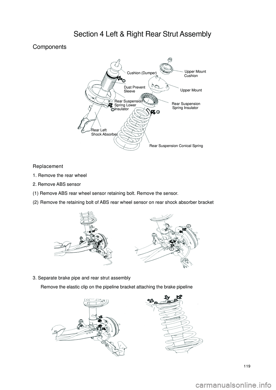
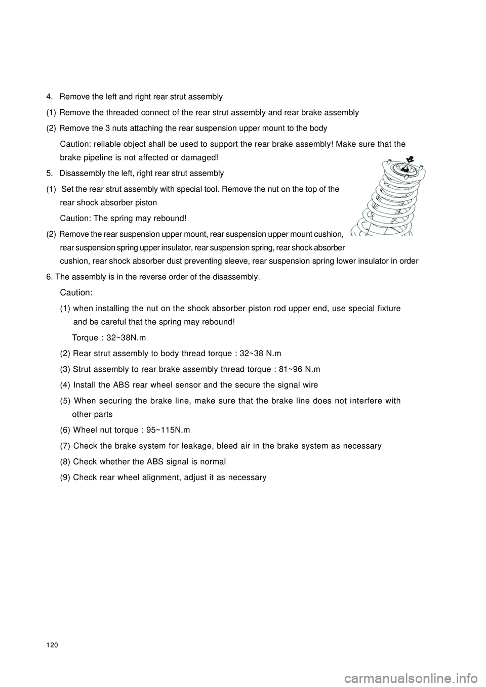
119Section 4 Left & Right Rear Strut AssemblyComponentsReplacement
1. Remove the rear wheel
2. Remove ABS sensor
(1) Remove ABS rear wheel sensor retaining bolt. Remove the sensor.
(2) Remove the retaining bolt of ABS rear wheel sensor on rear shock absorber bracket
3. Separate brake pipe and rear strut assembly
Remove the elastic clip on the pipeline bracket attaching the brake pipelineCushion (Dumper)Dust Prevent
SleeveRear Suspension
Spring Lower
InsulatorRear Left
Shock Absorber Upper Mount
CushionUpper MountRear Suspension
Spring Insulator
Rear Suspension Conical Spring
Page 127 of 392
1204. Remove the left and right rear strut assembly
(1) Remove the threaded connect of the rear strut assembly and rear brake assembly
(2) Remove the 3 nuts attaching the rear suspension upper mount to the body
Caution: reliable object shall be used to support the rear brake assembly! Make sure that the
brake pipeline is not affected or damaged!
5. Disassembly the left, right rear strut assembly
(1) Set the rear strut assembly with special tool. Remove the nut on the top of the
rear shock absorber piston
Caution: The spring may rebound!
(2) Remove the rear suspension upper mount, rear suspension upper mount cushion,
rear suspension spring upper insulator, rear suspension spring, rear shock absorber
cushion, rear shock absorber dust preventing sleeve, rear suspension spring lower insulator in order
6. The assembly is in the reverse order of the disassembly.
Caution:
(1) when installing the nut on the shock absorber piston rod upper end, use special fixture
and be careful that the spring may rebound!
Torque : 32~38N.m
(2) Rear strut assembly to body thread torque : 32~38 N.m
(3) Strut assembly to rear brake assembly thread torque : 81~96 N.m
(4) Install the ABS rear wheel sensor and the secure the signal wire
(5) When securing the brake line, make sure that the brake line does not interfere with
other parts
(6) Wheel nut torque : 95~115N.m
(7) Check the brake system for leakage, bleed air in the brake system as necessary
(8) Check whether the ABS signal is normal
(9) Check rear wheel alignment, adjust it as necessary
Page 166 of 392
1594Make a simulation test in a way of symptom simulation
5Inspect DTC
6Confirm symptomV. SYMPTOM SIMULATIONNOTES:
The most difficult conditions to handle in the fault troubleshooting are that the fault symptom dose not appear.
Under the circumstances, make sure first to make a comprehensive analysis to the fault described by the
customer, then to simulate an environment that is similar or the same with the conditions when the fault of the
customer's vehicle occurred. No matter how rich the experience of the technician is and how skillful he is, if
he make a fault troubleshooting analysis without confirm the fault symptom, it is inevitable for him to neglect
some important factors and incorrectly guess, which may cause barriers to repair. For example, if a fault
occurs only when the engine is cool or if a fault occurs only caused by a vibration from pavement and so on,
when the engine is checked in the hot or static state, it is no way to confirm. Because of vibration, high-
temperature or seeping water (Vapor) often causes some faults that are difficult to reappear. So, here are
some effective symptom simulation tests.
KEY POINTS OF SYMPTOM SIMULATION TEST:
In the symptom simulation test, no doubt it is important to confirm the fault symptom, but the fault position or
fault components must be also found out. So, before the test and the pre-inspection of connection, narrow the
range of the circuit where faults may occur according to the fault symptom. Then make a symptom simula-
tion test to see if the circuit measured is normal; the fault symptom is also verified at the same time.
1. Way of Vibration: When vibration may be the major cause of the fault.
For example:
(a) Use your hand to gently vibrate the sensor that is considered the cause of the fault, in order to check if it
is ineffective.
(b) Softly rock the connector and harness in horizontal and vertical direction.
Notes: Hard rock may cause the relay circuit open.
2. Way of Spraying Water: When rainy weather or wet environment may be the major cause of the fault.
(a) Spray water on the vehicle to check if the fault occurs.
NOTES:
�yBe sure not to directly spray water into the engine compartment. Spray the water on the face of the
radiator to change the temperature and humidity indirectly.
�yBe sure not to spray water onto electronic devices and controllers.