warning GEELY CK 2008 Owner's Guide
[x] Cancel search | Manufacturer: GEELY, Model Year: 2008, Model line: CK, Model: GEELY CK 2008Pages: 392, PDF Size: 38.86 MB
Page 291 of 392

284Note: This fault only applies to the condition that the system can communicate with the scan
meter (ABS ECU Power supply is normal), and there is no DTC set. 2 Afte r the e ngine is s tarte d, AB S
Warning Light is normally onLik e ly Caus e s
[De s cription]
One of the Likely Ca use s is tha t
ABS warning light drive module is da mage d or
there is a n ope n in the ABS wa rning light
circuit.�z The warning light drive module is da mage d
�z A B S w a r ning light dr ive module c ir c uit ope n
�z ABS ECU is damagedRepair the wire harnessCheck whether there is an open circuit in the wire be-
tween the ECU and ABS warning light drive module Check the ABS warning light drive moduleReplace Abn. No Ye s Replace the ABS ECUOk
Page 296 of 392

289III. ABS System CheckIte mIgnition
Switch ShiftTe rminal Pole Standard Unit
Battery Voltage OFF 25-8 10.1~
14.5 V
Battery Voltage
(
s ole noid va lve)OFF 9-24 10.1~
14.5 V
P owe r supply
in s ula t ionOFF 8-4 0.00~
0.5 V
Ground insula tion OFF 8-24 0.00~
0.5 V
P owe r supply
volta geON 8-4 10.1~
14.5 V
OFF Warning light goe s off Visua l inspec tion
ON Wa rning light goes on Visua l inspec tion
OFF Warning light goe s off Visua l inspec tion
ONWa rning light goes on
for a bout 1.7 se c onds
then goes offVisual inspection
B r a ke light s w it c h
peda l not de presse dON 8-18 0. 0~
0.5 V
B r a ke light s w it c h
peda l de pre sse dON 8-18 10. 0~
14.5 V
Diagnostic interface OFFDia gnostic inte rfa c e
K & 70.0~
0.5Ω
LF Wheel Speed
Sensor ResistanceOFF 1-20 1.2~
1.3 KΩ
RF Wheel Speed
Sensor ResistanceOFF 19-20 1.2~
1.3 KΩ
LR Wheel Speed
Sensor ResistanceOFF 5-6 1.0~
1.3 KΩ
RR Wheel Speed
Sensor ResistanceOFF 22-23 1.0~
1.3 KΩ
LF Whe e l Se nsor
Output VoltageOFF 1-2 3.4~
14.8 MV/Hz
RF Whe e l Se nsor
Output VoltageOFF 19-20 3.4~
14.8 MV/Hz
LR Whe e l Se nsor
Output VoltageOFF 5-6 >12.2 MV/Hz
RR Wheel Sensor
Output VoltageOFF 22-23 >12.2 MV/Hz
Spee d Se nsor Output
Voltage RatioABS Warning LightECU not connected
Connect ECUMaximum peak voltage
Minimum peak voltage≦2
Page 302 of 392

295V. ABS Assembly ReinstallationNote: the plug of the ABS assembly hydraulic outlet can only be removed after the brake pipe is
installed, lest the foreign object will enter the brake system.1. Install the ABS assembly to the bracket, tighten the torque: 20+4Nm.
2. Remove the plug of the hydraulic outlet, installed the brake pipe. Make sure that the brake pipe is
correctly installed.
3. Install the brake pipe connected to the master cylinder.
4. The brake pipe torque is 12+4Nm (M10 x 1) and 15+3Nm (M12 x 1).
5. Fill the new brake fluid into the reservoir until the liquid level reach the MAX and bleed it as specified.
6. With the ignition switch ON, ABS Warning Light must goes on for 1.7 seconds then goes off.
7. Clear the DTC memory, check if there is DTC again.
8. Drive the vehicle to confirm the ABS function (you must feel that the pedal rebound).VI. ECU ProgramNote: when replacing the HECU or ECU, you shall program the new ECU, otherwise the ABS
Warning Light flashes and the system can not operate normally.Use the scan meter to program the ECU based on the following procedure:Connect the scan meter with the diagnostic interfaceSelect function 07, Press OK button to confirmEnter code 01901 and Press OK button to confirmSelect function 07, Press OK button to confirm, quit the diagnosticEnd
Page 313 of 392

3063. Check for leakage if the reading changes and vacuumize it again.
4. Refill the new HFC-134a refrigerant if the reading doesn’t change.
Fill the new HFC-134a refrigerant
1. Connect the intermediate pipe to the refrigerant steel jar.
2. Open the refrigerant steel jar valve.
3. Weigh the refrigerant steel jar to charge the right refrigerant volume (refrigerant refill 630g¡À20g).Warning:•Check for air leakage or any other leakage when refilling large amount of refrigerant into the
Refrigeration system. The operator is recommended to fill small amount of refrigerant first to
prevent the refrigerant from leakage, which will result in ozonosphere damage.•It is very dangerous to open the engine high pressure side valve if filling the refrigerant with
the service tank. The pressure in the service tank will rise during the operation, which will
result in the service tank explosion. The exploded mental fragment and the splashed refrigerant
will hurt the operator badly. Therefore, do close the high pressure side valve when the engine
is working.4. Open the manifold gauge low pressure side valve.
5. Close the manifold gauge low pressure side valve when the manifold gauge low pressure side reading is
increased to 0.098Mpa{1.0kgf/cm2}.
6. Check cooling pipeline/hose for leakage with leak detector.
•Proceed to step 8 if there is no leakage.
•Tighten the union joint if there is leakage at the loosened union joint and go to next step.
7. Re-check the leaked points.
•Go to next step if there is no leakage after tightening the union joint.
•If there is still leakage at the same union joint, drain refrigerant and repair the union joint. Repeat
the filling procedure and vacuum it.
8. Open the valve at the low pressure side of the manifold gauge. Fill the refrigerant until the refrigerant
tank weight from the one mentioned in Step 3 drop to 250g.
9. Close the valve at the low pressure side of the manifold gauge.
10. Start the engine and switch on A/C.
11. Open the valve at the low pressure side of the manifold gauge. Fill the refrigerant until the refrigerant
tank weight from the one mentioned in Step 3 to specified value.
12. Close the valve at the low pressure side of the manifold gauge and the valve of the refrigerant steel jar.
13. Stop the engine and A/C compressor.
Page 330 of 392

3231. Front Bumper Removal and Installation
(1) Disconnect the negative (--) terminal cable from the battery. Disconnect fog lamp wire;
(2) Remove the mudguard skirt to front bumper clip;
(3) Remove the attaching bolt of the the front fender and panel and the front bumper sub-assembly;
(4) Remove the front bumper set screw and the clip. Remove the front bumper mounting plate and the
positioning screw of the seat;
(5) Remove the bolt which connecting front bumper mounting bracket with the vehicle body;
(6) Pull the front bumper assembly and the secondary bumper assembly together out of the vehicle body.
Separate the front bumper mounting bracket from the rail, front bumper mounting plate from the front
bumper mounting plate seat;
(7) Remove the front bumper mounting plate seat from the vehicle body;
(8) Remove the secondary bumper assembly and the front bumper mounting bracket sub-assembly;
(9) Remove front bumper mounting plate;
(11)Remove front bumper cushion. Remove the front license plate. Remove the mounting plate assembly;
(12)Remove fog lamp;
(13)The installation is in the reverse order of the removal.
2.Notice For Removal Of The Front Bumper
(1) Pull the front bumper to separate it from the bumper rail.
(2) Uniformly pull it by force to prevent the front bumper mounting plate and seat from damage.
Warning
�
Page 331 of 392

324(II) Engine HoodEngine Hood Removal / Installation
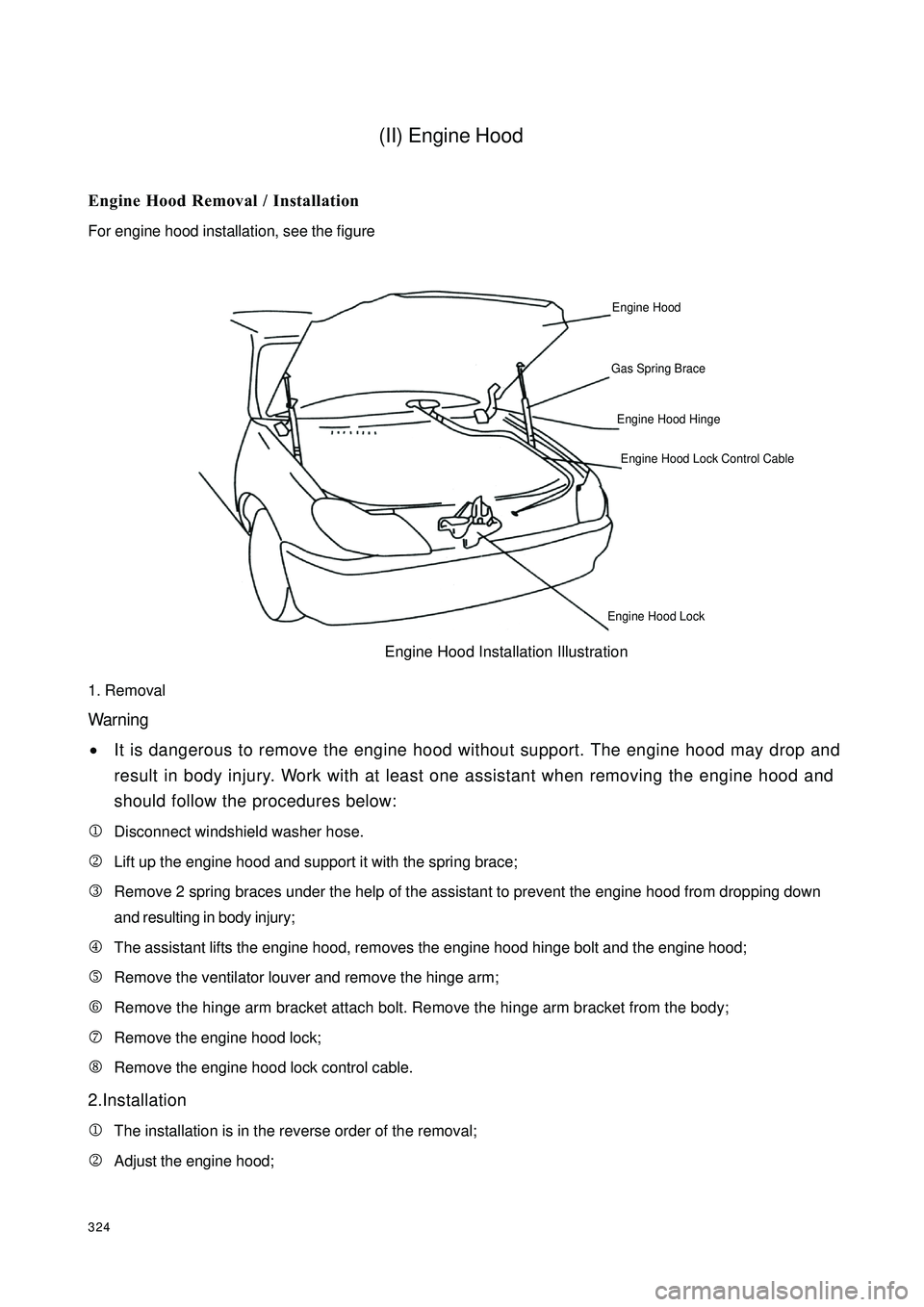
For engine hood installation, see the figure
1. Removal
Warning
•It is dangerous to remove the engine hood without support. The engine hood may drop and
result in body injury. Work with at least one assistant when removing the engine hood and
should follow the procedures below:
1Disconnect windshield washer hose.
2Lift up the engine hood and support it with the spring brace;
3Remove 2 spring braces under the help of the assistant to prevent the engine hood from dropping down
and resulting in body injury;
4The assistant lifts the engine hood, removes the engine hood hinge bolt and the engine hood;
5Remove the ventilator louver and remove the hinge arm;
6Remove the hinge arm bracket attach bolt. Remove the hinge arm bracket from the body;
7Remove the engine hood lock;
8Remove the engine hood lock control cable.
2.Installation
1The installation is in the reverse order of the removal;
2Adjust the engine hood;Engine HoodGas Spring BraceEngine Hood Hinge Engine Hood Lock Control CableEngine Hood LockEngine Hood Installation Illustration
Page 335 of 392

3281.Rear trunk Lid Removal/Installation
Warning
It is dangerous to remove the rear trunk lid spring before supporting the rear trunk lid. The rear
trunk lid may drop and result in body injury. Fully open the rear trunk lid, support the rear trunk
lid before removing the brace.
Remove rear trunk lid under the help of the assistant.(1) Disconnect the negative (--) terminal cable from the battery;
(2) Disconnect rear trunk wire harness connector. Pull the rear trunk lid wire harness out from the rear
trunk;
(3) Remove rear trunk door lock cylinder assembly. Pull out the rear trunk door lock cable;
(4) Remove rear trunk lid spring;
(5) Remove rear trunk lid hinge connecting bolt. Remove the rear trunk lid;
(6) Remove rear trunk lid hinge seat mounting nut. Remove the rear trunk lid hinge seat and the rear trunk lid
hinge
(7) Remove rear trunk door oil filler cable assembly;
(8) Remove cushion;
(9) Remove rear trunk lid hinge pin. Remove rear trunk lid hinge from the bracket;
(10) Remove rear trunk lid weatherstrip;
(11) Remove rear trunk lid inside trim board clip, Remove rear trunk lid inside trim board;
(12) Remove rear license plate assembly mounting nut , Remove rear license plate assembly;
(13) The installation is in the reverse order of the removal.;
(14) Adjust the rear trunk lid. (See rear trunk lid adjustment)2.Rear trunk Lid Adjustment(1) Measure the clearance and height between the rear trunk lid and vehicle body.
(2) Loose the rear trunk lid hinge mounting bolt or the rear trunk latch mounting screw and reinstall the rear
trunk lid if it is not as specified.
Clearance
a: 3.74mm
b: 1.0mm
c: 4.0mm
(3) Tighten the rear trunk lid hinge bolt;
(4) Close the rear trunk lid
Page 337 of 392

3302.Notice On Removing The Rear Bumper
(1) Pull the rear bumper out to separate it from the bumper rail.Warning
If only one side of the rear bumper is separated from the bumper rail, the bumper may drop and
result in body injury. Be careful not to make the bumper drop before separating the rear bumper
from the bumper rail.3.Notice On Installing The Rear Bumper(1) Press the rear bumper joint into the vehicle body to connect the rear bumper mounting bracket assembly
and the bumper rail.
(2) Insert the rear bumper end tab into the corresponding hole of the rear fender to flush with the outer
surface.
Page 343 of 392

3362. RetractorThe retractor is pre-tensioner. The retractor will pre-tension the seat belt when something emergency hap-
pens to prevent passengers from being hurt. It can sense the vehicle acceleration and the acceleration of the
belt being pulled out.
The retractor belt can be pull out and drawn back freely. It will not be locked at 12° around the safety
position, but locked at over 27°. The passenger can move in small area. The pre-tensioner will transmit within
5ms~10ms when something emergency happens to tension and lock the belt.Notice:1 . Check the product for damage, crack and rust before installation.
2 . Put the retractor vertically and the belt can be pulled out. Check if the belt can be pulled out
and around. Check if the retractor works.
3 . When installing the pretensioned seat belt, check the transmittor head pin for slant and rust.
The transmitter in the pretensioned seat belt can be used for 15 years after installation.
4 . Check if the belt buckle and the attachment matches the connecting mode of the to-be-installed
vehicle module. Check if the opening of the buckle is flexible.
5 . See if the screw thread of the nut welded on the cover is clear when installing the bolt. Assemble
the bolt after clearing the welding residue if there is any.
6. When the retractor belt is pulled out, there should be no obstacles around the belt (such as,
wire harness ect) , Remove the obstacles and make sure the retractor and the belt will not be
scratched.
3.Front seat belt removal/installation
Warning:
Do not remove retractor.(1) Turn the ignition switch to LOCK.
(2) Disconnect the negative (--) terminal cable from the battery
for 1min.
(3) Remove B- pillar lower frame.
(4) Pry the seat belt which is used to install the tension wheal.
Use a screwdriver to pry off the stop plate of the seat
belt connector with tensioner.
(5) Disconnect the seat belt connector with tensioner.
Remove 2 set bolts on the hang ring and remove the hang
ring.
(6) Remove two set bolts in the retractor and remove the
front seat belt.
(7) The installation is in the reverse order of the removal.Stop PlateBoltFront Seat BeltScrew
BoltLid
Page 344 of 392

337(8) Make sure the warning light of the airbag system on for 6s and off.
If the warning light of the airbag system is not as specified, it means system fault. Check with the OBD (on-
board diagnostics).4.Rear Seat Belt Removal / InstallationWarning
Do not remove retractor.
(1) Fold rear seat back.
(2) Remove B pillar upper inside trim.
(3) Remove rear trunk partition.
(4) Remove bolt.
(5) Remove rear seat belt.
(6) The installation is in the reverse order of the removal.
5.Rear Seat Belt Buckle Removal / Installation
(1) Remove rear seat cushion.
(2) Remove the bolt.
(3) Remove rear seat belt buckle.
(4) The installation is in the reverse order of the removal.
6. Seat Belt Inspection
(1) Ensure correct installation of seat belt.
(2) Check the metal component of the seat belt for damage.
(3) If the vehicle has been vibrated during the accident, pull out the
seat belt from the retractor, observe by eye and touch the seat
belt with hand to ensure that there is no scratch (load limit retractor
does not operate).
�zReplace the seat belt if it is not as specified in the technical specification.Seat BeltPullAnchorNickanchorage