warning GEELY CK 2008 User Guide
[x] Cancel search | Manufacturer: GEELY, Model Year: 2008, Model line: CK, Model: GEELY CK 2008Pages: 392, PDF Size: 38.86 MB
Page 199 of 392

19210. INSPECT PARK BRAKE SWITCH
(1) Disconnect the connector from the park brake switch.
(2) Pull up the hand brake, inspect continuity between its terminal and ground.
Hand brake is pulled up: Continuity
Hand brake is released: No continuity
11. INSPECT BRAKE FLUID LEVEL WARING LIGHT
(1) Disconnect the connector from the brake fluid level sensor.
(2) Turn the ignition ON, the brake fluid level warning light should go out.
(3) Directly connect its connector terminal to the harness terminal with a wire, the brake fluid level warning
light should light up.
12. INSPECT BRAKE FLUID LEVEL WARING SWITCH
(1) Remove the reservoir cap
(2) Disconnect the connector from the reservoir.
(3) Inspect continuity between terminals
Float up: No continuity
(4) Use siphon to take fluid out of the reservoir.
(5) Inspect continuity between terminals
Float down: Continuity
(6) Pour the fluid into the reservoir
13. INSPECT THE REAR DEFROST INDICATOR
(1) Turn the ignition switch ON, and start the engine
(2) Press the defrost switch, the rear defrost indicator will light up
(3) Turn the ignition OFF, the rear defrost indicator should go out.
14. INSPECT THE REAR DEFOG INDICATOR
(1) The rear fog indicator will light up as the rear fog lamp lights, the terminal B1 is at the high electric
potential.
15. INSPECT THE SEAT BELT WARNING INDICATOR
(1) Disconnect the seat belt switch connector in the driver's side, the belt warning indicator should go out at
this time.
(2) Short connector terminal to the ground, the belt warning indicator should light up.
Page 207 of 392

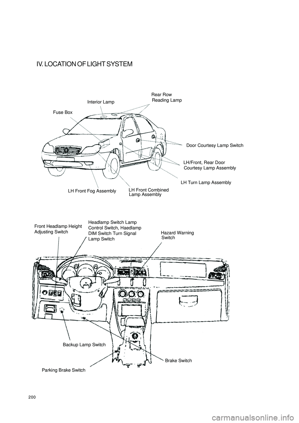
200IV. LOCATION OF LIGHT SYSTEMFuse BoxInterior LampRear Row
Reading LampLH Turn Lamp Assembly
Lamp Assembly LH Front Fog Assembly
Front Headlamp Height
Adjusting SwitchHeadlamp Switch Lamp
Control Switch, Haedlamp
DIM Switch Turn Signal
Lamp SwitchHazard Warning
SwitchParking Brake SwitchBackup Lamp Switch
Brake SwitchDoor Courtesy Lamp Switch
LH/Front, Rear Door
Courtesy Lamp Assembly
LH Front Combined
Page 211 of 392

2044. TURN SIGNAL AND HAZARD WARNING SYSTEM
5. BRAKE LAMP SYSTEMSymptom Suspec te d Area
1. HAZARD Fuse
2. Ce ntra l c ontrolle r
3. H a rne ss
1. Hazard warning switch
2. H a rne ss
1. Turn s igna l sw itc h
2. H a rne ss
1. Turn s igna l sw itc h
2. H a rne ss
1. Bulb
2. H a rne ss Only one bulb dose not light up “Haza rd" a nd “Turn” doe s not ope ra te
Ha za rd wa rning la mp doe s not ope ra te (Turn is
norma l)
Ha za rd wa rning la mp is abnormal (Ha za rd is
a bnorma l)
Turn signa l dose not light up in one direc tionSymptom Suspec te d Area
1. Bra ke la mp fus e
2. Brake lamp switch
3. H a rne ss
1. Brake lamp switch
2. H a rne ss
1. Bulb
2. H a rne ss
1. Bulb
2. H a rne ss Brake la mps on both side s do not light up
Br a ke la mp re ma ins a lw a ys O N
Bra ke la mp dose not light (One side )
High mounte d Bra ke la mp dose not light up
(Stop la mp is norma l)
Page 215 of 392

208(d) Inspect front and rear fog switch continuity
Inspect each terminal for continuity when the switch is on every position according to the table.
If it is not as specified, replace the switch.
2. BACK-UP LAMP SWITCH ASSEMBLY
Inspect back-up lamp switch continuity
Inspect continuity between the 2 terminals when the switch operates according to the table.
If it is not as specified, replace the switch.
3. BRAKE LAMP SWITCH ASSEMBLY
Inspect brake lamp switch assembly continuity
Inspect continuity between the 2 terminals when brake lamp switch operates
If it is not as specified, replace the switch.
4. HAZARD WARNING LAMP SWITCH ASSEMBLY
Inspect hazard warning lamp switch for continuity.
Inspect continuity between the 2 terminals when the switch operates
If it is not as specified, replace the switch.Switch position Tested terminal Condition
O FF 5BB3-9N B4-9N B1 No c ontinuity
Front fog la mp 5BB3-9NB4 Continuity
Re ar fog la mp 5BB3-9NB1 ContinuityS w it c h pos it ion T e s t e d t e r mina l C ondit ion
ON 1/2 Continuity
OFF 1/2 No continuitySwitc h position Te sted te rmina l Condition
ON (Ge a rshift le ve r is on REVERSE) 1/2 Continuity
OFF 1/2 No continuitySwitch position Tested terminal Condition
De pre ss on the bra ke pe da l 1/2 Continuity
Release the brake pedal 1/2 No continuity
Page 250 of 392

2435. Servicing operation shall be carried out 60s after the negative
(-) terminal cable is disconnected from the battery. In addition,
the disconnected negative (-) terminal cable shall be protected
with insulating tape for insulation.
In order to deploy an airbag within a certain time period after the
battery is disconnected, condenser in the ECU shall retain some
electrical energy. Otherwise, it could lead to a serious accident
because of the unexpected deployment of airbag.
6. During spray paint work, ECU, airbag assembly, clock spring
assembly, etc shall be removed and kept in place to avoid the effects of overheat. (Over 93¡æ)
7. When the SRS is serviced, a diagnostic scan meter is used to clear the DTC to enable the normal work of
the warning light.1 1 D AB Lo D r iv er a ir b ag , lo w p o s it io n
13 (Option) PAB Hi Passenger airbag, high position
14 (Option) PAB Lo Passenger airbag, low position
20Passenger Airbag Deactivation
Indic atorPassenger airbag deac tivation indic ator light
27PPD/ Passenger Airbag
Deac tivation Sw itch, HighPassenger airbag deac tivation sw itc h, high position
30 Crash Output Crash outputInsulating TapeBatteryCableDriver Side
Warning LampPassenger Side
Warning LampDriver Seat Inflation
Element & AirbagCrash Sensor &
Diagnostic ModuleFront/RH Inflation
Element & Airbag
Page 251 of 392

244II. TEST INSTRUMENTS
III. TROUBLESHOOTING1. Basic process of trouble diagnosis
�yDTC of the present fault may coexist with that of the history fault.
NOTICE:
�yAfter the new SRS ECU is installed, the warning light of the SRS, with the ignition switch ON, will be on
for 6s and then go out permanently, indicating SRS works normal. In this case, no service is needed.
Otherwise, system diagnosis and service shall be carried out.
�y If with the ignition switch ON, the warning light of the SRS is not on, the relevant circuits of the warning
light shall be serviced. Then go on with the operation and enable it to work.
2. Check SRS warning light
(1) Turn the ignition switch ON and find out whether the warning light is on.
(2) Six seconds after the process of ON-OFF, confirm that the warning light goes out permanently.
(3) Otherwise, diagnosis and checking have to be involved in.
3. System Diagnosis
The SRS ECU (HAE2.5) will perform a series of circular diagnostic tests to check the readiness of the SRS
functions. This test can avoid unexpected explosion of the restrain system and in the same time ensure the
necessary explosion in a crash. If a trouble is detected, the SRS ECU (HAE2.5) will store a proper DTC and
turn on the warning light indicating a trouble for service.Instrument Designation Usage
Check system troubles of the SRS, and
clear the DTC of ECU Diagnostic detector
(Hi-DS T Scan meter)
Spec ia l dia gnostic mete rWL Remains
ONUse scan meter and K line to
connect with Scan Meter ECULocate a
Trouble Trouble-
shootingClear
DTC
Page 254 of 392

247(2) Internal troubles
The micro controller can check the following items not
only in the initiation check but also in the circular diagnos-
tic check.
1Trigger transistor of ignition circuit: high-end transistor
can be checked not only in the initiation check but
also in the circular diagnostic check. However, since
the low-end transistor is open when connected in short
circuit to power source, it can only be checked in the
initiation check to avoid explosion.
2The ignition voltage is provided by supercharge
converter.
3The acceleration sensor performs selfcheck in the
initiation check.
4Range of allowed deviation of acceleration sensor in the circular diagnostic check.
5Microcontroller includes AD converter, ROM, RAM, etc.
6Status of safety sensor.NOTICE
The connectors of the squib circuit contain a
shorting bar. When the connector is not
connected, the unexpected deployment is
caused by the short in the circuit arising from
the contact of the positive (+) and negative (-)
terminals or the static electricity. If there is
poor connection for connectors, the symptom
may not be removed even when the shorting
bar is connected.14Ignition c irc uit 4 (passe nger se a t be lt pre tensione r), low re sistanc e
or short c irc uitB1 368
15 Ignition c ircuit 4 (passe nger se a t be lt pre tensione r), groundB1 369
16Ignition c ircuit 4 (passe nger se a t belt pre te nsione r), c onne c t topowe r sourceB1 370
17 High volta ge of powe r sourc e B1 111
18 Low volta ge of power sourc e B1 112
19Warning light trouble -c onne c te d to powe r sourc e or light bulb short
circuitB2 500
20 Warning light trouble -ground or filame nt ope n circ uitB2 500
21 Missing/mistake of the algorithm parameters B1 661
22 Previous crash recordedB1 650
23 Communic a tion trouble B1 407
23 Inte rna l trouble (se e the following ta ble) B1 620
24PADS(
pa ssenge r airba g de a ctiva tion switch)
, c onne c ted topowe r source or open c irc uitB1 527
25PADS(
passenger airbag deactivation switch)
, ground or short
circuitB1 528
26 PADS (passenger airbag deactivation switch), trouble B1 529
27 Cra sh output pin, groundB1 676
28 Cra sh output pin, short c irc uite d to power sourc e B1 677
29PADI (passenger airbag deactivation switch indicator light) error,
c onne c ted to powe r sourc e or light bulb short c irc uitB2 505
30PADI (passenger airbag deactivation switch indicator light) error,
ground or open c irc uitB2 505
31 Se a t be lt pre tensione r se pa ra te ignitionB1 657
32 Se a t be lt pre tensione r se pa ra te ignition for 6 time s B1 658
Page 255 of 392

248An external watchdog can check the operation situation of the microcontroller. The failure of the microcontroller
can trigger the watchdog, which in turn can reset the microcontroller and turn on the warning light.No. List of Trouble s Trouble De sc ription
1 M ic r oc ont r olle r�z AD c onve rte r or EEP ROM trouble (in
case of RAM and ROM failure, the
mic r oc ont r olle r w ill r e s e t a nd t he w a r ning
light will light up.)�z Activate trouble�z
Che ck the circ uit trouble�z Activate trouble�z Check the circuit trouble�z Activate trouble�z Chec k the c irc uit trouble�z Activate trouble�z Chec k the c irc uit trouble�z Activate trouble�z Check the circuit trouble�z Activate trouble�z Check the circuit trouble
6 Ignition volta ge�z Low
7 Wa tchdog/rese t�z Trouble
8 Maximum times of e xplosion of the se a t belt
pretensioner�z 6
9 Ene rgy stora ge time (self-support time )�z Short�z Ra nge of de via tion�z Se nsor not in ste ady mode�z Se nsor se lfc hec k trouble
11 Continuous abortion of ignition circ uit che c k�z None xec ution of c irc ula r diagnostic test
(Repeated algorithm calculation)�z Close for 2 or more tha n 2 sec onds�z Sa fe ty se nsor is open c irc uit when
calculating the trouble with algorithm
13 Ignition c urre nt�z All the ignition currents are normal
when the current SRS is deployed
14 No c onfirma tion of side SRS ignition�z Eve n if the SRS ECU (HAE2.5) ha ve
received for 5 times the ignition information
during the HSIS ignition cyc le, the side SRS
a irba g ignition c a n not be ve rifie d by SRS
ECU (HAE2.5). Seat belt pretensioner ignition circuit (if realized)
5 P asse nger se a t be lt pre tensione r ignition c irc uit
(if realized) 2 P asse nger airba g ignition c ircuit
3 P asse nger airba g ignition c ircuit (if re a lize d)[Ta ble ] Inte rna l troubles pre dic te d by SRS ECU (HAE2.5)
10 Accelerometer
12 Sa fe ty se nsor6 Driver airbag ignition circuit (if realized)
7 P asse nger airba g ignition c ircuit (if re a lize d) 4
Page 256 of 392

249(3) Clear DTCs
When ECU diagnostic tester (Hi-DSTM) receives the "Clear DTCs" command from the serial interface,
the DTCs stored in ECU will be cleared off. But if an internal DTC is recorded or there is one crash
record, the command will not be executed.
5. Trouble display (Warning light ON)
(1) Light bulb check
When working voltage is supplied to SRS ECU (HAE2.5) through battery, SRS ECU (HAE2.5) lights up
the warning light to check the light bulb. In the initiation stage, the light will be on for 6s at the frequency
of 1Hz and then go out. To give notice of the presence of troubles to the driver, the warning light will
remain on after the working voltage is supplied. If the history troubles happened for less than 5 times, the
warning light will be on for 6s after ignition on and then go out. In the initiation stage, the SRS ECU
(HAE2.5) will not check crash and arrest deployment until the circuit of SRS ECU (HAE2.5) goes
stable.
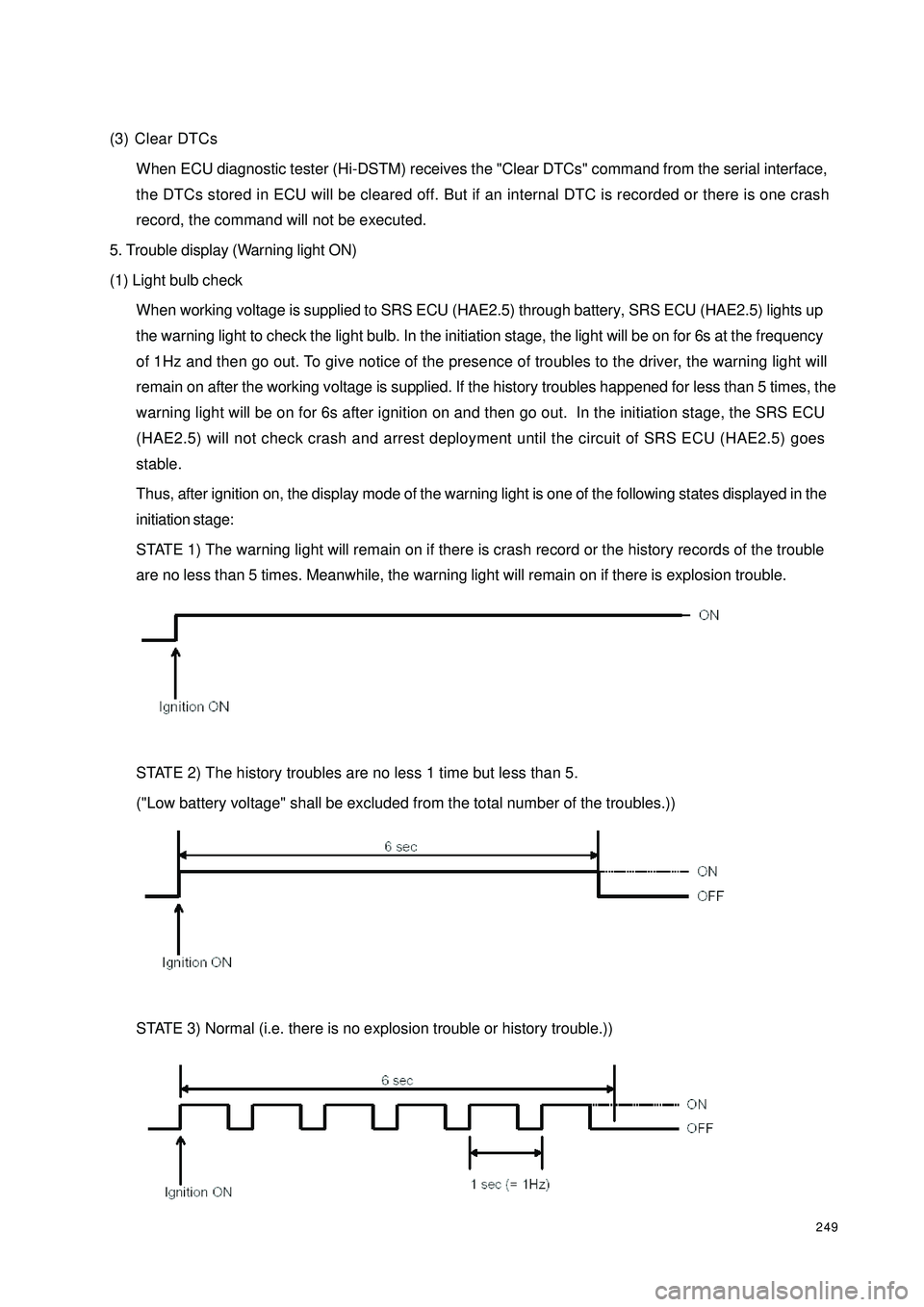
Thus, after ignition on, the display mode of the warning light is one of the following states displayed in the
initiation stage:
STATE 1) The warning light will remain on if there is crash record or the history records of the trouble
are no less than 5 times. Meanwhile, the warning light will remain on if there is explosion trouble.
STATE 2) The history troubles are no less 1 time but less than 5.
("Low battery voltage" shall be excluded from the total number of the troubles.))
STATE 3) Normal (i.e. there is no explosion trouble or history trouble.))
Page 257 of 392

250(2) Trouble indication
1In case of a trouble, the warning light will indicate. If the external trouble is a history trouble, the indication
will be cancelled. When the history trouble happens for no less than 5 times, the indicator light will remain
on even if there is no more trouble. "Low battery voltage" shall not be counted in the total number of
troubles.
2Only a service worker can reset a displayed or history trouble. The internal troubles of a SRS ECU
(HAE2.5) or the "crash record" of a trouble cannot be reset, in which case the SRS ECU (HAE2.5) shall
be replaced.
(3) Microcontroller-independent warning light on
Microcontroller with definitive troubles cannot fulfill its functions, thus cannot control the warning light. In
this case, the warning light will light up through proper circuit regardless of the microcontroller as stated
below:
�yMalfunction of the battery supplying power to SRS ECU (HAE2.5): the warning lights are turned
on continuously by means of the drive function of the selfcheck light.
�yLoss of internal working voltage: the warning light remains on.
�yReset due to trigger failure of the watchdog: the warning light blinks.
�yMicrocontroller out of work: the warning light always lights up.
�yIncomplete insertion of SRS ECU (HAE2.5) connector: the warning light remains on by means of
a shorting bar.
The diagnostic procedures can well be illustrated as follows:
If it is found that the SRS warning light remains on, follow the undermentioned procedures to check even if
the light goes out eventually. First, a scan meter is used to check the location of the trouble.
Then£¬go on with the checking in accordance with specific methods and procedures for the correspondent
location.
a. If the result indicates that it is an internal trouble or that the SRS is already detonated, replace the
ECU directly.
b. Troubleshooting.