fuel GEELY CK 2008 Workshop Manual
[x] Cancel search | Manufacturer: GEELY, Model Year: 2008, Model line: CK, Model: GEELY CK 2008Pages: 392, PDF Size: 38.86 MB
Page 2 of 392

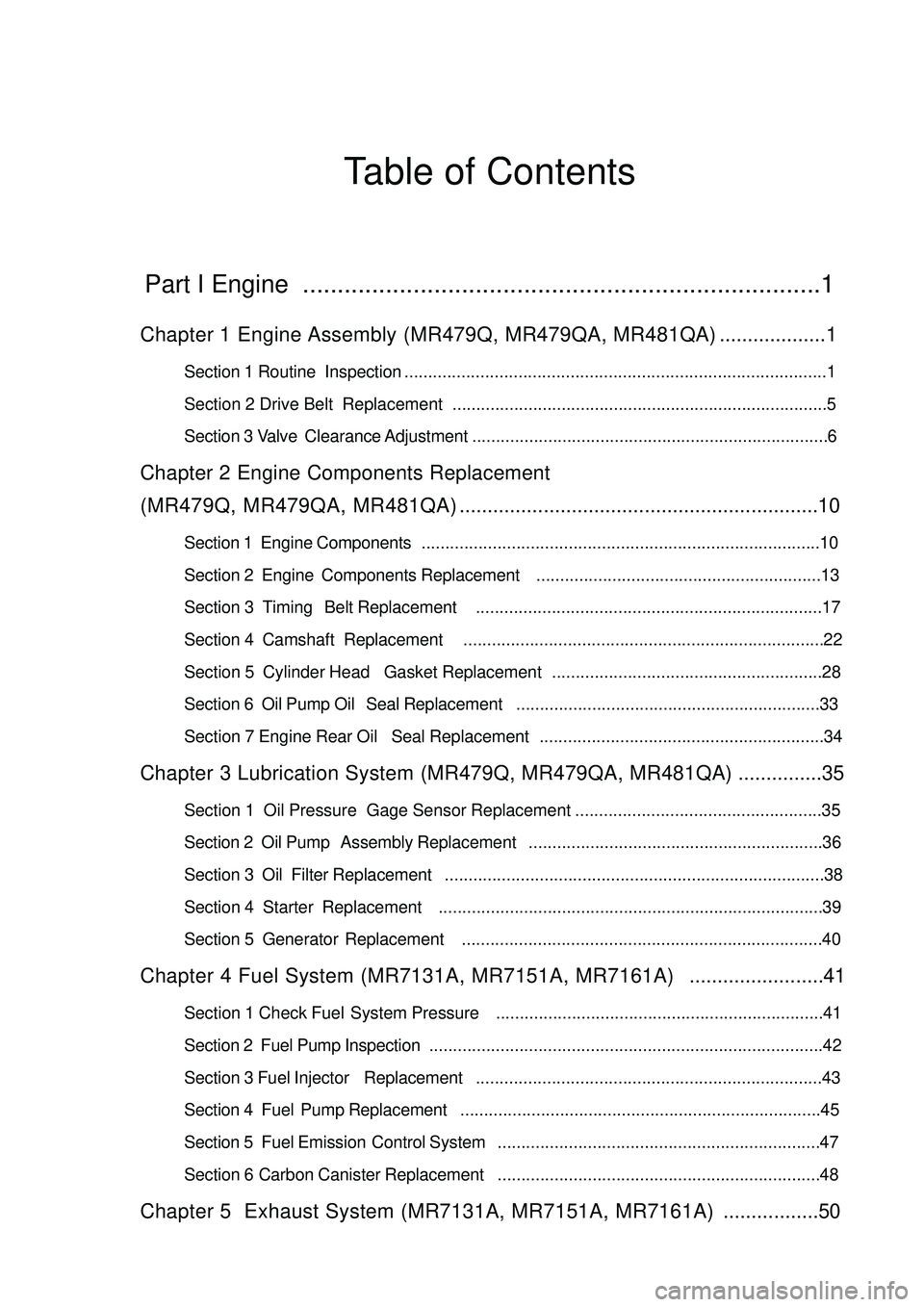
Table of ContentsPart I Engine ...........................................................................1Chapter 1 Engine Assembly (MR479Q, MR479QA, MR481QA)...................1Section 1 Routine Inspection.........................................................................................1
Section 2 Drive Belt Replacement ...............................................................................5
Section 3 Valve Clearance Adjustment...........................................................................6Chapter 2 Engine Components Replacement
(MR479Q, MR479QA, MR481QA)................................................................10Section 1 Engine Components....................................................................................10
Section 2 Engine Components Replacement............................................................13
Section 3 Timing Belt Replacement.........................................................................17
Section 4 Camshaft Replacement............................................................................22
Section 5 Cylinder Head Gasket Replacement.........................................................28
Section 6 Oil Pump Oil Seal Replacement................................................................33
Section 7 Engine Rear Oil Seal Replacement............................................................34Chapter 3 Lubrication System (MR479Q, MR479QA, MR481QA)...............35Section 1 Oil Pressure Gage Sensor Replacement....................................................35
Section 2 Oil Pump Assembly Replacement..............................................................36
Section 3 Oil Filter Replacement................................................................................38
Section 4 Starter Replacement.................................................................................39
Section 5 Generator Replacement............................................................................40Chapter 4 Fuel System (MR7131A, MR7151A, MR7161A)........................41Section 1 Check Fuel System Pressure.....................................................................41
Section 2 Fuel Pump Inspection...................................................................................42
Section 3 Fuel Injector Replacement.........................................................................43
Section 4 Fuel Pump Replacement............................................................................45
Section 5 Fuel Emission Control System....................................................................47
Section 6 Carbon Canister Replacement....................................................................48Chapter 5 Exhaust System (MR7131A, MR7151A, MR7161A).................50
Page 17 of 392

10Chapter 2 Engine Components Replacement
(MR479Q, MR479QA, MR481QA)Section 1 Engine ComponentsComponent 1Air Filter Assembly W/ Hose
Accelerator Control
Cable Assembly
Heater Inlet Hose
Heater Outlet Hose
Fuel Sub-Assembly
Efi Fuel Pipe Clamp
MT:
Transmission
Control Cable
Assembly
AT :
Transmission Control Cable Assembly MT:
Clutch Release
Cylinder Assembly
Radiator Outlet Pipe Radiator Inlet Pipe
Starter AssemblyAT: Oil Cooler Outlet Pipe
AT: Oil Cooler Inlet Pipe
Radiator Assembly
BatteryFront Exhaust
Pipe Assy.3-way catalytic
converterMufflerTail PipeFigure 20
Page 20 of 392

13Section 2 Engine Components Replacement1. Avoid gasoline ejection when work.
2. Drain the coolant to empty.
3. Remove air filter assembly with hose. See (Figure 23)
4. Remove battery
5. Remove fuel delivery pipe sub-assembly
6. Disconnect water hoses, disconnect heater outlet hose
from A/C hose.
7. Loose nut, remove accelerator control cable
8. Remove throttle body assembly
9. Remove power steering pump reservoir assembly
10. Remove front exhaust pipe assembly
11. Remove steering gear boot
12. Seperate steering column assembly. See (Figure 24)
13. Remove front wheel hub nut
14. Disconnect front wheel vehicle speed sensor (with ABS)
15. Detach steering tie rod ball stud pin assembly
16. Detach front lower swing arm sub-assembly
17. Detach front propeller assembly. See (Figure 25)
Detach front propeller from the shaft hub with plastic hammer.
18. Disconnect transmission shift cable or gear shift level assembly
19. Disconnect clutch cylinder assembly or disconnect clutch cable
20. Detach engine assembly and transaxle
(a) Hoisting engine ;
(b) Remove 3 bolts. Detach the right engine mounting bracket. See (Figure 26) ;
(c) Remove 1 bolt. Detach the left engine mounting bracket;
(d) Remove 1 bolt. Detach the rear engine mounting bracket;
(e) Remove engine and transaxle and put them on the pallet;
(f) Jack up the boday.Figure 23
Figure 24
Figure 25 Figure 26
Page 23 of 392

16(c) Install and uniformly tighten connecting bolt in the sequence shown inthe figure.
Torque: 64N. m
62. Install manual transaxle assembly
63. Install starter assembly
64. Install power steering pump bracket
65. Install power steering pump adjusting bracket with 2 bolts.
66. Connect power steering pump assembly
67. Install engine assembly and transaxle
68. Connect left, right, front and rear lower suspension arm sub-assembly
69. Connect left and right tie rod ball stud pin assembly
70. Connect left, right and front vehicle speed sensor (with ABS)
71. Install left & right nuts on the front shaft hub
72. Install front exhaust pipe assembly
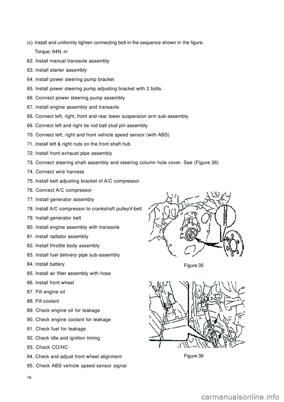
73. Connect steering shaft assembly and steering column hole cover. See (Figure 36)
74. Connect wire harness
75. Install belt adjusting bracket of A/C compressor
76. Connect A/C compressor
77. Install generator assembly
78. Install A/C compressor to crankshaft pulleyV-belt
79. Install generator belt
80. Install engine assembly with transaxle
81. Install radiator assembly
82. Install throttle body assembly
83. Install fuel delivery pipe sub-assembly
84. Install battery
85. Install air filter assembly with hose
86. Install front wheel
87. Fill engine oil
88. Fill coolant
89. Check engine oil for leakage
90. Check engine coolant for leakage
91. Check fuel for leakage
92. Check idle and ignition timing
93. Check CO/HC
94. Check and adjust front wheel alignment
95. Check ABS vehicle speed sensor signalFigure 35
Figure 36
Page 35 of 392

28Section 5 Cylinder Head Gasket ReplacementComponent 1Figure 68Vane Pump Assembly V/ Power Steering
Throttle Body AssemblyGasketDipstick
Inlet Pipe
Gasket
Wire HarnessO-RingTiming Chain Or Timing Belt Cover No. 2
Crankshaft Or Pulley Cover Sub-AssemblyFan PulleyFuel Delivery Pipe No.1
Page 37 of 392

30Component 3Figure 70Air Filter Assembly W/ HoseEngine Hood
Right Wiper Arm
Left Wiper Arm
Right Scuttle Ventilation Grille
Left Scuttle Ventilation Grille Right Engine Mounting Bracket
Generator
AssemblyAccelerator Cable AssemblyWiper Arm Subassembly
EFI Fuel Hose Clamp
Fuel Pipe Sub-Assembly
Heater Outlet Hose A
Radiator Outlet Hose Radiator Inlet HoseHeater Inlet Hose
Vane-Type Pump
V-Belt V/ Power Steering
V-Belt No.1Fan & Generator V-Belt
Page 38 of 392

31Replacement1. Disconnect all the wire harnesses and the cables on the engine connected to the car body.
2. Detach air filter assembly with hose
3. Disconnect oil pipe and water hose
4. Loose positive and negative cables of the battery.
5. Detach propeller shaft. Detach front exhaust pipe assembly
6. Loose engine left & right rear brackets after hoisting the engine.
7. Disconnect all the other connectors between the engine and the car body.
8. See "Provision 20, Section 2, Chapter 2". Lift the car body and take out the engine assembly.
9. Remove A/C compressor to the crankshaft pulleyV-belt.
10. Remove power steering pump V-belt.
11. Detach water pump fan pulley.
12. Disconnect ignition coil and high voltage cable.
13. Detach cylinder head cover sub-assembly.
14. Detach generator assembly.
15. Detach the camshaft.
16. Detach the throttle body assembly
17. Detach intake manifold stay No. 2.
18. Take out the dipstick
19. Detach No. 1 fuel delivery pipe
20. Detach the wire harness.
21. Detach the steering assisting pump assembly
22. Detach exhaust manifold. See (Figure 71)
23. Pry cylinder head from the dowel pin on the cylinder block.
See (Figure 72)
24. Remove the cylinder head gasket.
25. Install cylinder head gasket
26. Install cylinder head sub-assembly
27. Install exhaust pipe assembly.
(a) Install the new gasket and exhaust manifold with 5
bolts. Torque: 34N. m
(b) Install exhaust manifold stay with 2 bolts.
(c) Install upper heat shield with 4 bolts
Torque: 17N. mFigure 71
Figure 72
Page 39 of 392

3228. Install power steering adjusting pole
29. Install power steering pump assembly
30. Install wire harness.
31. Install No. 1 fuel delivery pipe
32. Set the new gasket on cylinder head with flange upward. Install water inlet hose. See
(Figure 73)
33. Install manifold stay No. 2
34. Connect front exhaust pipe assembly
35. Install throttle body assembly
36. Install camshaft
37. Install engine cylinder head cover
38. Hoist the engine back to the compartment.
39. Install engine right left and rear brackets
40. Install propeller shaft
41. Install ignition coil and high pressure cables. Install air filter assembly with hose
42. Install oil pipe and water hose
43. Install left & right front tire
44. Install all the wire harnesses and cables on the engine connected to car body
45. Check compression pressure
46. Check CO/HC. Check idle and ignition timingFigure 73
Page 48 of 392

41Chapter 4 Fuel System
(MR7131A, MR7151A, MR7161A)Section 1 Check Fuel System Pressure1. Remove the fuel tank from the vehicle
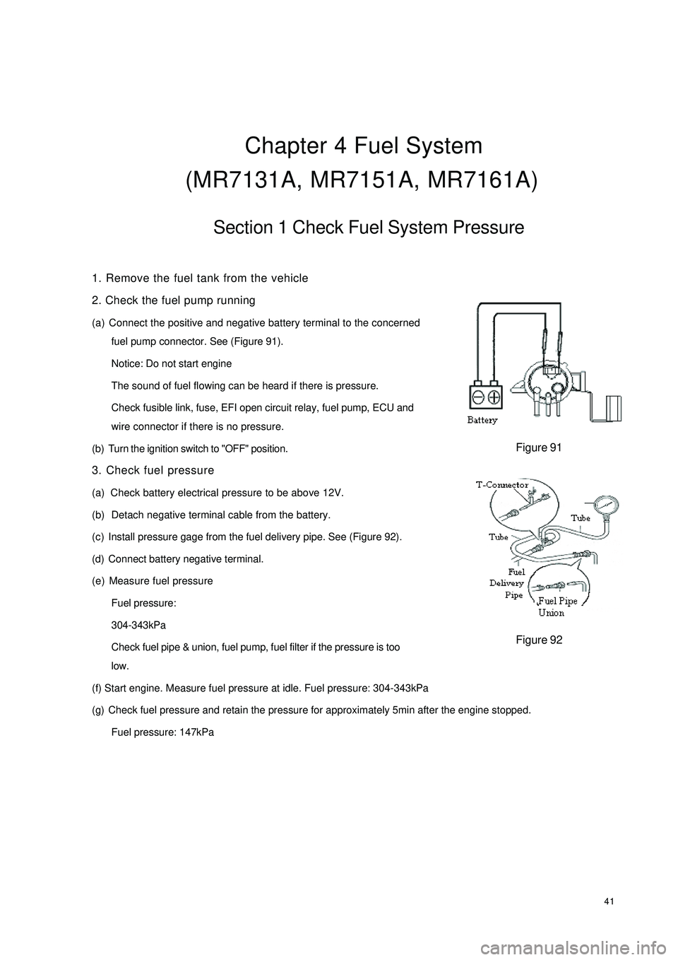
2. Check the fuel pump running
(a) Connect the positive and negative battery terminal to the concerned
fuel pump connector. See (Figure 91).
Notice: Do not start engine
The sound of fuel flowing can be heard if there is pressure.
Check fusible link, fuse, EFI open circuit relay, fuel pump, ECU and
wire connector if there is no pressure.
(b) Turn the ignition switch to "OFF" position.
3. Check fuel pressure
(a) Check battery electrical pressure to be above 12V.
(b) Detach negative terminal cable from the battery.
(c) Install pressure gage from the fuel delivery pipe. See (Figure 92).
(d) Connect battery negative terminal.
(e) Measure fuel pressure
Fuel pressure:
304-343kPa
Check fuel pipe & union, fuel pump, fuel filter if the pressure is too
low.
(f) Start engine. Measure fuel pressure at idle. Fuel pressure: 304-343kPa
(g) Check fuel pressure and retain the pressure for approximately 5min after the engine stopped.
Fuel pressure: 147kPaFigure 91Figure 92
Page 49 of 392

42Section 2 Fuel Pump Inspection1. Fuel pump
(a) Check fuel pump resistance, 0.2~3.0 at 20°. Replace fuel pump if the resistance is not as specified.
See (Figure 93)
(b) Fuel pump running:
Check fuel pump by connecting with battery. Replace fuel pump or wire if the running is not as specified.
See (Figure 94).
The test should be conducted within 10s to prevent coil from damage.
2. Fuel injector assembly
Injection Volume: 40~50cm3/s
Error between each injector: less than 10 cm3Replace injector if the injection volume is not as specified.
(a) Check for leakage: Disconnect the cable from the battery. The fuel drop/min is no more than 1 drop.
Figure 93 Figure 94 Ohmmeter
Battery Ω