tow GEELY CK 2008 Workshop Manual
[x] Cancel search | Manufacturer: GEELY, Model Year: 2008, Model line: CK, Model: GEELY CK 2008Pages: 392, PDF Size: 38.86 MB
Page 94 of 392

87(3) Dust cover retainer shall be assembled well, otherwise the dust seal effect will be af-
fected
(4) Dust cover fixing nut torque: 20~25N.m
(5) Make sure the shift number words on the top of shift lever ball face towards the driving
direction of the vehicle, properly tighten the set screw of the shift lever
(6) Check whether the shift control is flexible and reliable; the shift lever shall be vertical
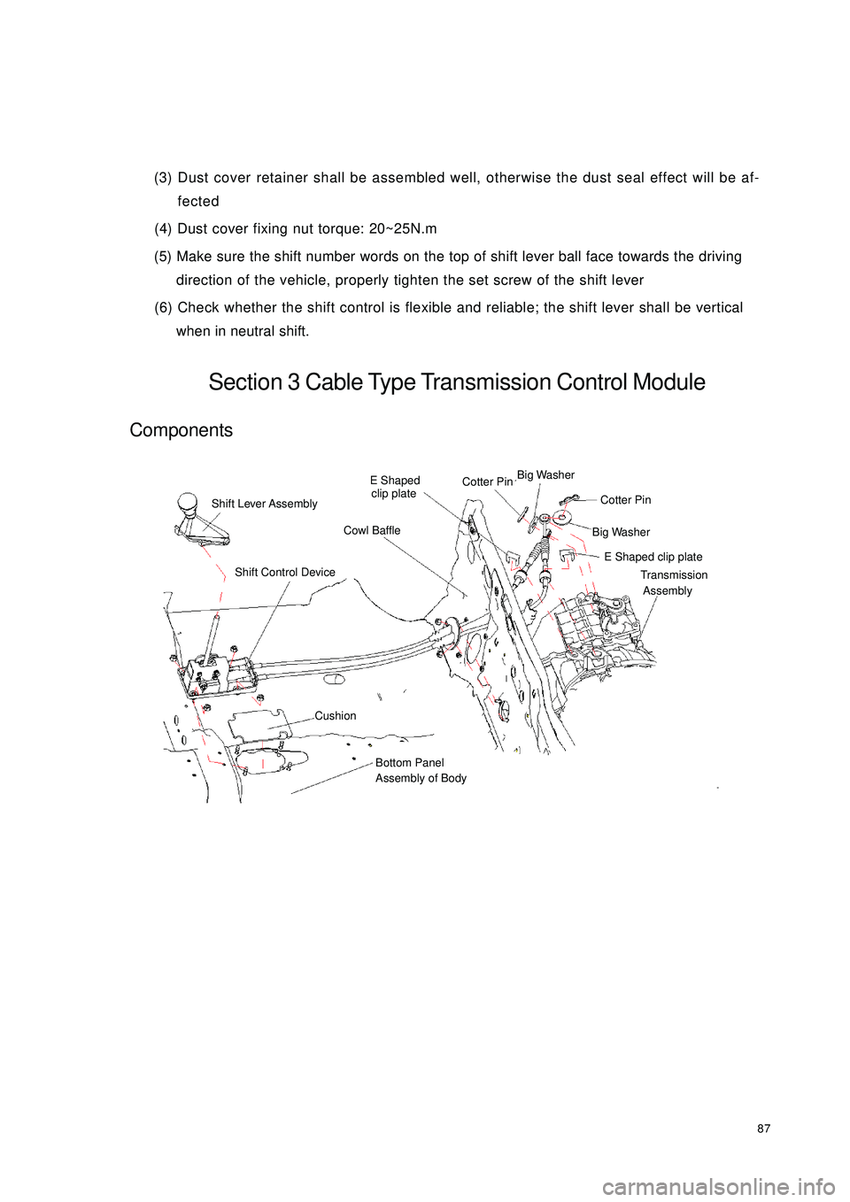
when in neutral shift.Section 3 Cable Type Transmission Control ModuleComponentsShift Lever AssemblyE Shaped
clip plateCotter PinBig Washer Big Washer Cotter PinE Shaped clip plateTransmission
AssemblyCowl BaffleShift Control DeviceCushionBottom Panel
Assembly of Body
Page 96 of 392

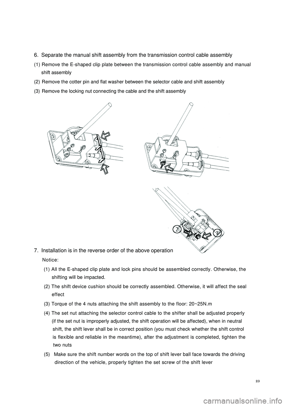
896. Separate the manual shift assembly from the transmission control cable assembly
(1) Remove the E-shaped clip plate between the transmission control cable assembly and manual
shift assembly
(2) Remove the cotter pin and flat washer between the selector cable and shift assembly
(3) Remove the locking nut connecting the cable and the shift assembly
7. Installation is in the reverse order of the above operation
Notice:
(1) All the E-shaped clip plate and lock pins should be assembled correctly. Otherwise, the
shifting will be impacted.
(2) The shift device cushion should be correctly assembled. Otherwise, it will affect the seal
effect
(3) Torque of the 4 nuts attaching the shift assembly to the floor: 20~25N.m
(4) The set nut attaching the selector control cable to the shifter shall be adjusted properly
(if the set nut is improperly adjusted, the shift operation will be affected), when in neutral
shift, the shift lever shall be in correct position (you must check whether the shift control
is flexible and reliable in the meantime), after the adjustment is completed, tighten the
two nuts
(5) Make sure the shift number words on the top of shift lever ball face towards the driving
direction of the vehicle, properly tighten the set screw of the shift lever
Page 347 of 392

3403.Side Panel Removal/Installation
(1) Using the flat screwdriver wrapped with vinyl tape, disconnect the
clip.
(2) Pull the side panel towards yourself and remove the plate from the
instrument panel and remove the side panel.
(3) The installation is in the reverse order of the removal.
4.Steering Column Cover Removal/Installation
(1) Remove upper cover.
(2) Remove the ignition key.
(3) Remove the screw.
(4) Remove lower cover.
(5) The installation is in the reverse order of the removal.
5.Combination Instrument Panel Removal/Installation
(1) Remove the screw.
(2) Using the flat screwdriver wrapped with vinyl tape, disconnect the clip.
(3) Pull combination instrument panel towards yourself. Remove pillar.
(4) The installation is in the reverse order of the removal.
6.Lower End Shield Removal/Installation
(1) Using the flat screwdriver wrapped with vinyl tape, disconnect the
clip.
(2) Pull the lower end shield towards yourself and remove clipA and
plate B from the instrument panel and remove lower end shield.
(3) Disconnect the engine hood cable.
The installation is in the reverse order of the removal.