transmission oil GEELY CK 2008 Workshop Manual
[x] Cancel search | Manufacturer: GEELY, Model Year: 2008, Model line: CK, Model: GEELY CK 2008Pages: 392, PDF Size: 38.86 MB
Page 3 of 392

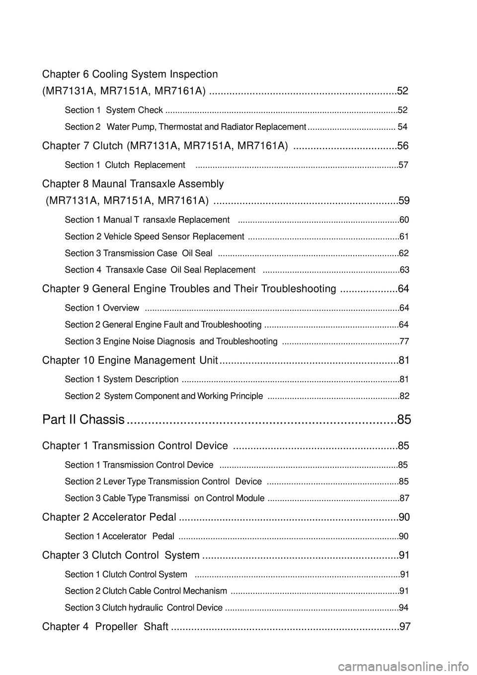
Chapter 6 Cooling System Inspection
(MR7131A, MR7151A, MR7161A).................................................................52Section 1 System Check
Section 2 Water Pump, Thermostat and Radiator Replacement.................................... 54Chapter 7 Clutch (MR7131A, MR7151A, MR7161A)....................................56Section 1 Clutch Replacement...................................................................................57Chapter 8 Maunal Transaxle Assembly
(MR7131A, MR7151A, MR7161A)................................................................59Section 1 Manual Transaxle Replacement..................................................................60
Section 2 Vehicle Speed Sensor Replacement
Section 3 Transmission Case Oil Seal..........................................................................62
Section 4 Transaxle Case Oil Seal Replacement........................................................63Chapter 9 General Engine Troubles and Their Troubleshooting....................64Section 1 Overview........................................................................................................64
Section 2 General Engine Fault and Troubleshooting.......................................................64
Section 3 Engine Noise Diagnosis and Troubleshooting................................................77Chapter 10 Engine Management Unit..............................................................81Section 1 System Description.........................................................................................81
Section 2 System Component and Working Principle......................................................82Part II Chassis............................................................................85Chapter 1 Transmission Control Device.........................................................85Section 1 Transmission Control Device.........................................................................85
Section 2 Lever Type Transmission Control Device......................................................85
Section 3 Cable Type Transmission Control Module......................................................87Chapter 2 Accelerator Pedal............................................................................90Section 1 Accelerator Pedal..........................................................................................90Chapter 3 Clutch Control System....................................................................91Section 1 Clutch Control System....................................................................................91
Section 2 Clutch Cable Control Mechanism.....................................................................91
Section 3 Clutch hydraulic Control Device.......................................................................94Chapter 4 Propeller Shaft...............................................................................97...............................................................................................52
..............................................................61
Page 17 of 392

10Chapter 2 Engine Components Replacement
(MR479Q, MR479QA, MR481QA)Section 1 Engine ComponentsComponent 1Air Filter Assembly W/ Hose
Accelerator Control
Cable Assembly
Heater Inlet Hose
Heater Outlet Hose
Fuel Sub-Assembly
Efi Fuel Pipe Clamp
MT:
Transmission
Control Cable
Assembly
AT :
Transmission Control Cable Assembly MT:
Clutch Release
Cylinder Assembly
Radiator Outlet Pipe Radiator Inlet Pipe
Starter AssemblyAT: Oil Cooler Outlet Pipe
AT: Oil Cooler Inlet Pipe
Radiator Assembly
BatteryFront Exhaust
Pipe Assy.3-way catalytic
converterMufflerTail PipeFigure 20
Page 62 of 392

55(5) Disconnect auto-transmission oil cooler input pipe (Auto-transmission).
(6) Disconnect auto-transmission oil cooler output pipe (Auto-transmission).
(7) Remove 4 bolts from the radiator mounting bracket. See (Figure 129).
(8) Detach radiator assembly, Remove 3 bolts. Detach the fan and fan shroud. See (Figure 130).
Figure 127 Figure 128
(9) Install the cooling fan assembly
(a) Fix the reservoir assembly on the cooling fan bracket with the bolt. Torque: 16 N. m.
(b) Install the fan and fan shroud with 3 bolts. Torque: 7.5N. m.
(c) Install the cooling fan assembly to radiator assembly with 3 bolts. Torque: 16N. m.
(d) Connect the overflow pipe on the reservoir assembly and radiator assembly. Fix it with the spring
band.
(f) The installation of the radiator assembly is in the reverse order of the removal.
Page 67 of 392

60Section 1 Manual Transaxle Replacement1. Open the engine hood
2. Remove the battery
3. Remove clutch cylinder sub-assembly. See (Figure 140)
4. Detach transmission shift cable assembly. See (Figure 141)
5. Remove the connector and turn on the back-up lamp switch connector.
6. Disconnect vehicle speed sensor
Disconnect vehicle speed sensor connector.
7. Detach the front exhaust pipe
8. Drain transmission oil
9. Detach left & right front wheel hub nut
10. Detach left & right front wheel speed sensor (ABS)
11. Detach front balance rod
12. Detach left & right tie-rod with ball stud pin
13. Detach front balance rod
14. Detach left & right lower swing arm
15. Detach left & right front propeller assembly
16. Hoist the engine from compartment. See "Provision 20, Section 2, Chapter 2"
17. Detach starter assembly
18. Detach engine mounting bracket
19. Detach manual transaxle assembly
20. Install engine mounting bracket
21. Install manual transaxle assembly
22. Connect engine vibration insulating cushions
23. Install starter assembly
24. Install left & right front propeller assembly
25. Connect left & right lower swing arm
26. Connect left & right tie-rod with ball stud pin
27. Connect front balance rod
28. Connect left & right front speed sensor (ABS)
29. Installleft & right front shaft nut
30. Install front exhaust pipe
31. Connect speedometer sensor connector.
32. Connect back-up lamp switch connector.
33. Connect transmission shift cable assembly. See (Figure 141)
34. Install clutch sub-pump assembly. See (Figure 140)Figure 140
Figure 141
Page 69 of 392

62Section 3 Transmission Case Oil Seal1. Remove transmission case oil seal. See (Figure 144)
2. Install transmission case oil seal. See (Figure 145)
Notice:
Be careful not to damage oil seal lip.
Figure 144 Figure 145