lock GEELY MK 2008 User Guide
[x] Cancel search | Manufacturer: GEELY, Model Year: 2008, Model line: MK, Model: GEELY MK 2008Pages: 416, PDF Size: 25.19 MB
Page 28 of 416
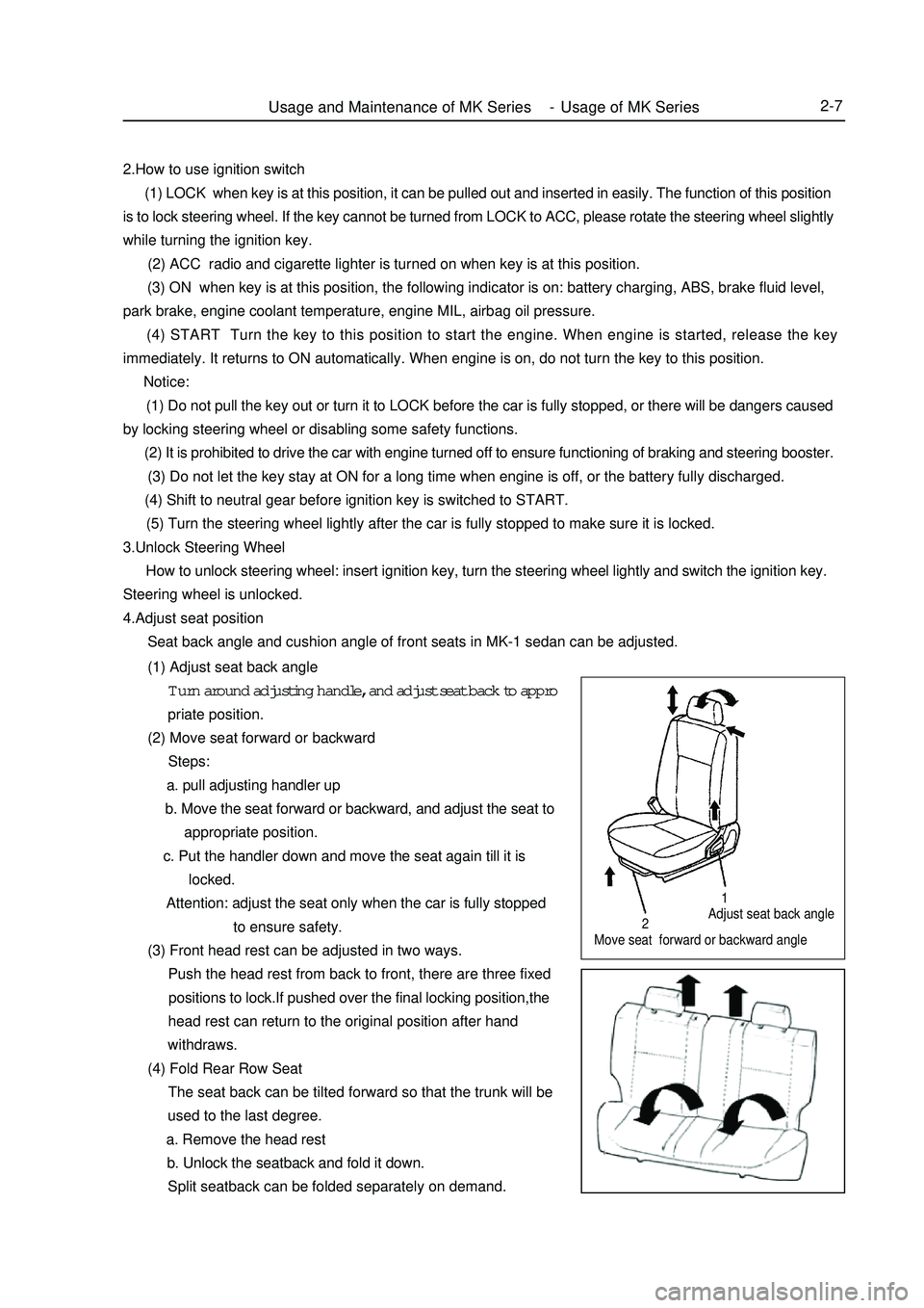
Adjust seat back angle
Move seat forward or backward angleUsage and Maintenance of MK Series - Usage of MK Series2-7212.How to use ignition switch
(1) LOCK when key is at this position, it can be pulled out and inserted in easily. The function of this position
is to lock steering wheel. If the key cannot be turned from LOCK to ACC, please rotate the steering wheel slightly
while turning the ignition key.
(2) ACC radio and cigarette lighter is turned on when key is at this position.
(3) ON when key is at this position, the following indicator is on: battery charging, ABS, brake fluid level,
park brake, engine coolant temperature, engine MIL, airbag oil pressure.
(4) START Turn the key to this position to start the engine. When engine is started, release the key
immediately. It returns to ON automatically. When engine is on, do not turn the key to this position.
Notice:
(1) Do not pull the key out or turn it to LOCK before the car is fully stopped, or there will be dangers caused
by locking steering wheel or disabling some safety functions.
(2) It is prohibited to drive the car with engine turned off to ensure functioning of braking and steering booster.
(3) Do not let the key stay at ON for a long time when engine is off, or the battery fully discharged.
(4) Shift to neutral gear before ignition key is switched to START.
(5) Turn the steering wheel lightly after the car is fully stopped to make sure it is locked.
3.Unlock Steering Wheel
How to unlock steering wheel: insert ignition key, turn the steering wheel lightly and switch the ignition key.
Steering wheel is unlocked.
4.Adjust seat position
Seat back angle and cushion angle of front seats in MK-1 sedan can be adjusted.
(1) Adjust seat back angle
Turn around adjusting handle, and adjust seat back to appro
priate position.
(2) Move seat forward or backward
Steps:
a. pull adjusting handler up
b. Move the seat forward or backward, and adjust the seat to
appropriate position.
c. Put the handler down and move the seat again till it is
locked.
Attention: adjust the seat only when the car is fully stopped
to ensure safety.
(3) Front head rest can be adjusted in two ways.
Push the head rest from back to front, there are three fixed
positions to lock.If pushed over the final locking position,the
head rest can return to the original position after hand
withdraws.
(4) Fold Rear Row Seat
The seat back can be tilted forward so that the trunk will be
used to the last degree.
a. Remove the head rest
b. Unlock the seatback and fold it down.
Split seatback can be folded separately on demand.
Page 31 of 416
2-10 must be running at medium speed without load. Increase the speed and load gradually with the
accumulation of breaking-in mileage.
b. Because the brake plat is not broken in on a new vehicle,in order to ensure safety and reduce wear,avoid
harsh brake, and brake for multiple times to break in the brake plate faster.
c. It is better to avoid driving vehicle on steep roads or in bad conditions during breaking-in period.
d. Pay special attention to engine coolant temperature meter and oil pressure meter.Check engine oil level
frequently and make sure engine works in normal temperature and good lubrication.
e. Maintain the vehicle strictly according to first-time maintenance requirements to bring the vehicle into
normal usage life under good condition.
7.vehicle towing
There are towing facilities both in the front and rear end of MK-1 sedan for towing other vehicles and being towed.
To ensure safety, pay attention to the following instructions when towing.
(1) Towing car Towing car should be started and shifted steadily.The speed should be no more than 40km/h.
(2) Follow the instructions below when being towed:
a. Steering system of the vehicle being towed works well.
b. Braking system of the vehicle being towed works well or it cannot be towed with a rope and must be
towed with the towing shaft instead.
c. Release park brake and shift the transmission to neutral gear when the vehicle is being towed.
d. Turn the ignition switch to ACC to allow turning signal lights,braking indicator to be turned on when
necessary.
e. The towing rope must be tensioned in the towing process.
f. If the purpose of towing is to start the engine, shift the transmission to the 2nd or 3rd gear to increase
engine speed. It is good for starting the engine.
8. Instructions to save fuel when using the vehicle
(1) Reasonable load Do not store useless articles in luggage compartment because they consumes fuel for
nothing.
(2) Correct driving style Instructions as follows:
a. When engine is started, do not heat it but press the accelerator pedal slightly, drive the vehicle slowly
and accelerate gradually.
b. Shift to higher gears when driving to allow the engine to work at appropriate engine speed and avoid
running the engine at low or high speed. The engine speed should be higher than 2500r/min when
driving, and higher than 3000r/min when up-shifting.
c. Keep the vehicle speed stable, and avoid harsh acceleration and frequent braking.
d. Pay attention to vehicle speed. Drive at high speed results in excessive fuel consumption.
(3) Organize vehicle usage well Pay attention to the following two instructions.
a. Organize vehicle usage time and avoid short trips. Because at the beginning when the vehicle is started
(around 1km), the engine has not reached its efficiency point, and the fuel consumption doubles
compared to regular.
b. Select a good driving route, avoid driving through the city or blocks with heavy traffic.
(4) Keep the vehicle under good work condition Strictly follow instructions to maintain the vehicle to make
sure the vehicle is under good technical working condition, and inspect and replace key parts that affect vehicle
fuel consumptions. For example:Usage and Maintenance of MK Series - Usage of MK Series
Page 32 of 416

2-11a. Keep air filter clean, Block of air filter affects engine air induction efficiency and increases fuel
consumption. So it must be cleaned and replaced in time.
b. Keep ignition system under good work condition. Bad connection or electricity leak of ignition coil and
power distributor or inappropriate gap or carbon residue of spark plug decreases ignition power supply
and efficiency, which leads to engine fuel consumption increase. So they need regular inspection and
repair to keep their good work condition.
c. Fuel feeding system works well. Often check if fuel feeder pipe leaks, and check if injectors and other
parts perform well on regular basis (electrical injection engines).
d. Keep regular tire pressure. If the tire pressure is not enough, vehicle rolling resistance increases and
engine fuel consumption increases accordingly. So tire pressure must be checked on time (around once
a week).Usage and Maintenance of MK Series - Usage of MK Series
Page 37 of 416
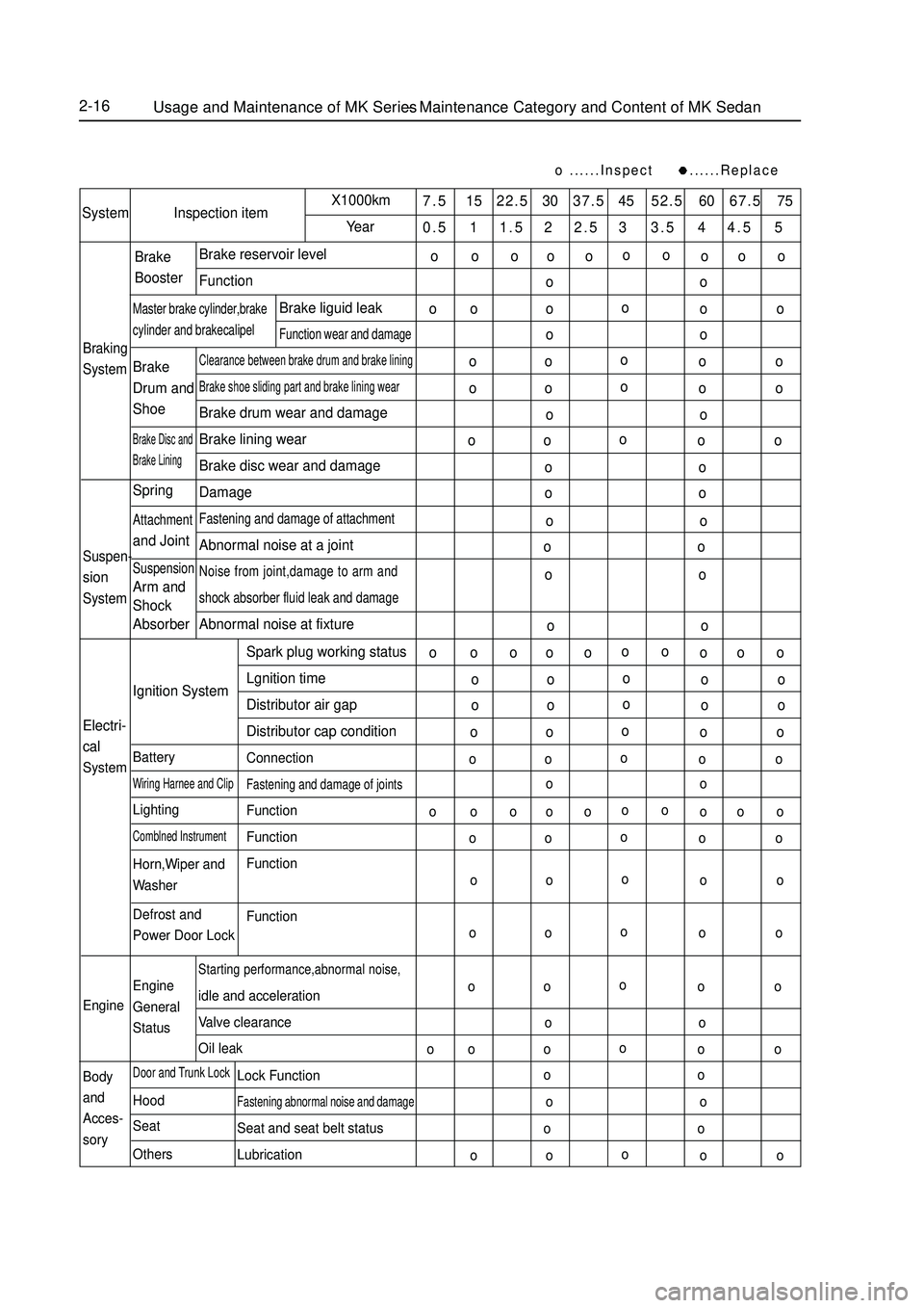
2-16......Inspect ......Replace7.5 15 22.5 30 37.5 45 52.5 60 67.5 75
0.5 1 1.5 2 2.5 3 3.5 4 4.5 5System Inspection itemX1000km
YearBraking
SystemBrake reservoir level
FunctionClearance between brake drum and brake liningBrake shoe sliding part and brake lining wearBrake drum wear and damage
Brake lining wear
Brake disc wear and damage
DamageFastening and damage of attachmentAbnormal noise at a jointNoise from joint,damage to arm and
shock absorber fluid leak and damageAbnormal noise at fixtureBrake
BoosterMaster brake cylinder,brakecylinder and brakecalipelBrake liguid leakFunction wear and damageBrake
Drum and
ShoeBrake Disc and
Brake LiningSuspen-sionSystemSpringAttachmentand JointSuspensionArm and
Shock
Absorber
Electri-
cal
SystemEngine
Body
and
Acces-
soryIgnition System
BatteryWiring Harnee and ClipLightingComblned InstrumentHorn,Wiper and
Washer
Defrost and
Power Door Lock
Engine
General
StatusDoor and Trunk LockHood
Seat
OthersStarting performance,abnormal noise,idle and acceleration
Valve clearance
Oil leakSpark plug working status
Lgnition time
Distributor air gap
Distributor cap condition
ConnectionFastening and damage of jointsFunction
Function
Function
FunctionLock FunctionFastening abnormal noise and damageSeat and seat belt status
LubricationUsage and Maintenance of MK Series - Maintenance Category and Content of MK Sedano
oo
o o o
o
o o ooo o
o o
ooo o
o o
o o
oo o
o o
oo o
o o
oo oo o
o o
o o
o o
o o
o o
o o
oo o o
o o ooo o
o o
oo o
o o
oo o
o o
oo o
o o
oo o
o o
oo o o
o o ooo o
o o
oo o
o o
oo o
o o
oo o
o o
oo o
o o
o o
ooo o
o o
oo oo oo oo o
Page 43 of 416
TableEngine AssemblyEngine Inspection3-2 Note:
Check the belt distortion at the specified point (see Figure 1-1).
When mounting a new belt, set the tensioning force to specified value.
After the belt has been operated more than 5 minutes, check and ensure the distortion not exceeding specified
value. (2) Make sure that the coolant level is above the neck of the radiator.
(3) Put the radiator cover in place, pressurize to 2.0Mpa, and keep the pressure for 1minute unless the coolant
leaks. (Mount a tester on the radiator cover, start the engine, and then shut down under a pressure 2.0Mpa).
(4) Check whether the coolant quantity in the dilatation can is between the mark "Low" and "Full".
(5) Check whether the radiator cover is clean; test whether the opening pressure of the main valve is 107.8KPa
with a radiator cover tester. The minimum opening pressure is 58.5KPa.
6. Check the battery.
(1) The terminal voltage of the battery is 12.5-12.9V at 20°C, and charge when the voltage value is less than
the specified value. Check whether the fusible cutout and the fuse are loose, corrosive or on.
7. Check the air filter.
(1) Whether the cover, the case or the element of the filter is distorted, corroded or damaged.
(2) Whether the air hose is damaged.
(3) Whether the air chamber is distorted or damaged.
(4) Whether the air filter element is blocked, polluted or damaged. If the filter element is blocked slightly,
remove the dirt by blowing the element from above.
(5) Whether there is any pollutant or dirt on the air filter support.
8. Check the spark plug.
(1) Spark generation.
a. Disconnect the coupling of the injector.
b. Remove the spark plug from the secondary wire.
c. Remove the spark plug.
d. Connect the spark plug to the secondary wire.
e. Ground the spark plug.
f. Start the engine, and check whether spark is generated.
Prompt: The starting time is not more than 1-2s.
(2) Clean the spark plug: The air pressure is not greater than 588kp and the time is not more than 20s.
(3) Check whether the thread and the insulator of the spark plug are damaged. Replace if necessary.
(4) Check the electrode gap of the spark plug: 0.8±0.1mm for MR479Q and MR479QA; 1±0.05mm for
MR481QA.
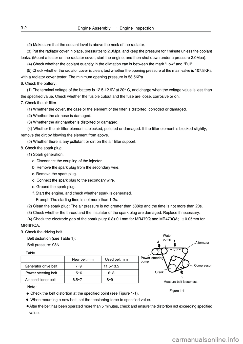
9. Check the driving belt.
Belt distortion (see Table 1):
Belt pressure: 98NMeasure belt loosenessCompressor
Crank Power steering
pumpWater
pump
Alternator2 1
3Figure 1-1New belt mm Used belt mm
Generator drive belt 7~9 11.5-13.5
Power steering belt 5~6 6~8
Air conditioner belt 6.5~7 8~9 -
Page 46 of 416

Table 3Section 2 Removal of the Engine Assembly from the Vehicle1. Avoid petrol overflowing (Disconnect from the fuel tank).
2. Remove the front wheel.Figure 1-5Engine AssemblyRemoval of the Engine Assembly from the Vehicle3-5CO
Normal
Low
HighHC
High
High
HighProblems
Bad idle speed
Bad idle speed
(HC reading fluctuates)
Bad idle speed
(Black smoke exhausts)Causes
1. Ignition fault:
Incorrect ignition timing;
Dirt, short circuit, or incorrect spark plug gap.
2. Incorrect valve gap.
3. Suction and exhaust valve leak.
4. Cylinder leaks.
1. Vacuum leaks.
PCV pipe . manifold;
Idle speed control valve;
Brake booster pipeline.
2. Spark lacks since the mixed gas is too thin.
1. Air filter is blocked.
2. PCV valve is blocked.
3. EFI system fails.
ECU fails.
Pressure regulator of fuel oil is out of order.
Water temperature sensor does not work.
Suction pressure/temperature sensor fails.
Injector fails.
The throttle position sensor fails.3. Discharge the coolant completely.
4. Remove the air filter assembly with hose (see Figure 1-5).
(1) Disconnect the joint of the temperature sensor and the wire
plug.
(2) Disconnect the vent duct from the hose of the air filter.
(3) Release the wire clip bolt on the air filter.
(4) Disconnect the hose of the air filter from the throttle body.
(5) Remove 3 bolts and the air filter assemblies.
5. Remove the battery.
6. Remove the fuel pipe sub-assembly.
7. Disconnect the water pipe; disconnect the water outlet pipe of the
heater from the air conditioner pipe.
8. Release the nut and remove the accelerator control cable. -
Page 49 of 416

Chapter 2 Engine MechanicalSection 1 Engine ComponentsComponent ViewFigure 2-1Engine MechanicalEngine Components3-8Upside of radiator support
Engine cover lock assembly
Starter assembly
Output pipe of oil cooler
Input pipe of oil coolerTransmission control cable assembly Fuel oil sub-assembly Accelerator control cable assemble
Water inlet pipe of heater
Water outlet pipe of heaterTransmission control cable assemblySuitable for 1.5L/1.6L(Tight coupling)Suitable for 1.3L/1.5L(Non-tight coupling) Radiator assemblyAir filter assembly with hose
Clutch release assembly
Water inlet pipe of radiator
Water outlet pipe of radiator
Battery -
Page 54 of 416
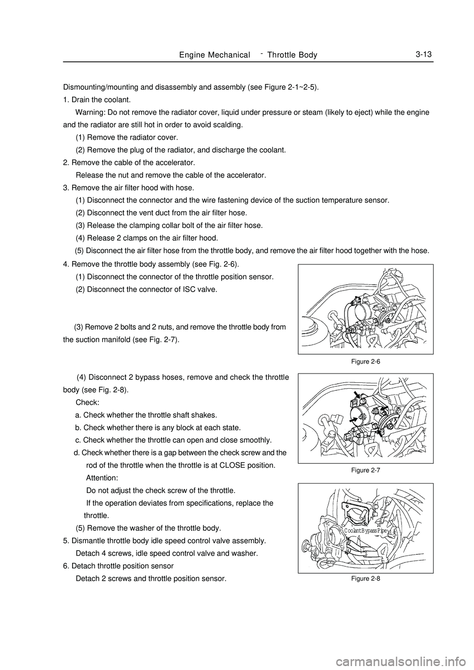
Dismounting/mounting and disassembly and assembly (see Figure 2-1~2-5).
1. Drain the coolant.
Warning: Do not remove the radiator cover, liquid under pressure or steam (likely to eject) while the engine
and the radiator are still hot in order to avoid scalding.
(1) Remove the radiator cover.
(2) Remove the plug of the radiator, and discharge the coolant.
2. Remove the cable of the accelerator.
Release the nut and remove the cable of the accelerator.
3. Remove the air filter hood with hose.
(1) Disconnect the connector and the wire fastening device of the suction temperature sensor.
(2) Disconnect the vent duct from the air filter hose.
(3) Release the clamping collar bolt of the air filter hose.
(4) Release 2 clamps on the air filter hood.
(5) Disconnect the air filter hose from the throttle body, and remove the air filter hood together with the hose.Figure 2-6
Figure 2-7
Figure 2-8Engine MechanicalThrottle Body3-134. Remove the throttle body assembly (see Fig. 2-6).
(1) Disconnect the connector of the throttle position sensor.
(2) Disconnect the connector of ISC valve.
(3) Remove 2 bolts and 2 nuts, and remove the throttle body from
the suction manifold (see Fig. 2-7).
(4) Disconnect 2 bypass hoses, remove and check the throttle
body (see Fig. 2-8).
Check:
a. Check whether the throttle shaft shakes.
b. Check whether there is any block at each state.
c. Check whether the throttle can open and close smoothly.
d. Check whether there is a gap between the check screw and the
rod of the throttle when the throttle is at CLOSE position.
Attention:
Do not adjust the check screw of the throttle.
If the operation deviates from specifications, replace the
throttle.
(5) Remove the washer of the throttle body.
5. Dismantle throttle body idle speed control valve assembly.
Detach 4 screws, idle speed control valve and washer.
6. Detach throttle position sensor
Detach 2 screws and throttle position sensor.Coolant Bypass Pipe -
Page 56 of 416
Chapter 3 Fuel SystemSection 1 Check Fuel System PressureOn-board inspection
1. Check the operation of the fuel pump.
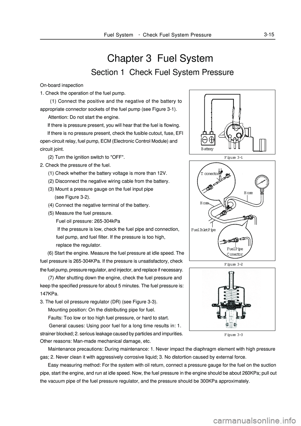
(1) Connect the positive and the negative of the battery to
appropriate connector sockets of the fuel pump (see Figure 3-1).
Attention: Do not start the engine.
If there is pressure present, you will hear that the fuel is flowing.
If there is no pressure present, check the fusible cutout, fuse, EFI
open-circuit relay, fuel pump, ECM (Electronic Control Module) and
circuit joint.
(2) Turn the ignition switch to "OFF".
2. Check the pressure of the fuel.
(1) Check whether the battery voltage is more than 12V.
(2) Disconnect the negative wiring cable from the battery.
(3) Mount a pressure gauge on the fuel input pipe
(see Figure 3-2).
(4) Connect the negative terminal of the battery.
(5) Measure the fuel pressure.
Fuel oil pressure: 265-304kPa
If the pressure is low, check the fuel pipe and connection,
fuel pump, and fuel filter. If the pressure is too high,
replace the regulator.
(6) Start the engine. Measure the fuel pressure at idle speed. The
fuel pressure is 265-304KPa. If the pressure is unsatisfactory, checkFigure 3-1
Figure 3-3 Figure 3-2Fuel SystemCheck Fuel System Pressure3-15the fuel pump, pressure regulator, and injector, and replace if necessary.
(7) After shutting down the engine, check the fuel pressure and
keep the specified pressure for about 5 minutes. The fuel pressure is:
147KPa.
3. The fuel oil pressure regulator (DR) (see Figure 3-3).
Mounting position: On the distributing pipe for fuel.
Faults: Too low or too high fuel pressure, or hard to start.
General causes: Using poor fuel for a long time results in: 1.
strainer blocked; 2. serious leakage caused by particles and impurities.
Other reasons: Man-made mechanical damage, etc.
Maintenance precautions: During maintenance: 1. Never impact the diaphragm element with high pressure
gas; 2. Never clean it with aggressively corrosive liquid; 3. No distortion caused by external force.
Easy measuring method: For the system with oil return, connect a pressure gauge for the fuel on the suction
pipe, start the engine, and run at idle speed. Now, the fuel pressure in the engine should be about 260KPa; pull out
the vacuum pipe of the fuel pressure regulator, and the pressure should be 300KPa approximately.Battery
T conector
Hose
Hose
Fuel Inlet Pipe
Fuel Pipe
Conector -
Page 60 of 416
Section 5 Carbon Canister Replacement1. Check and replace the canister.
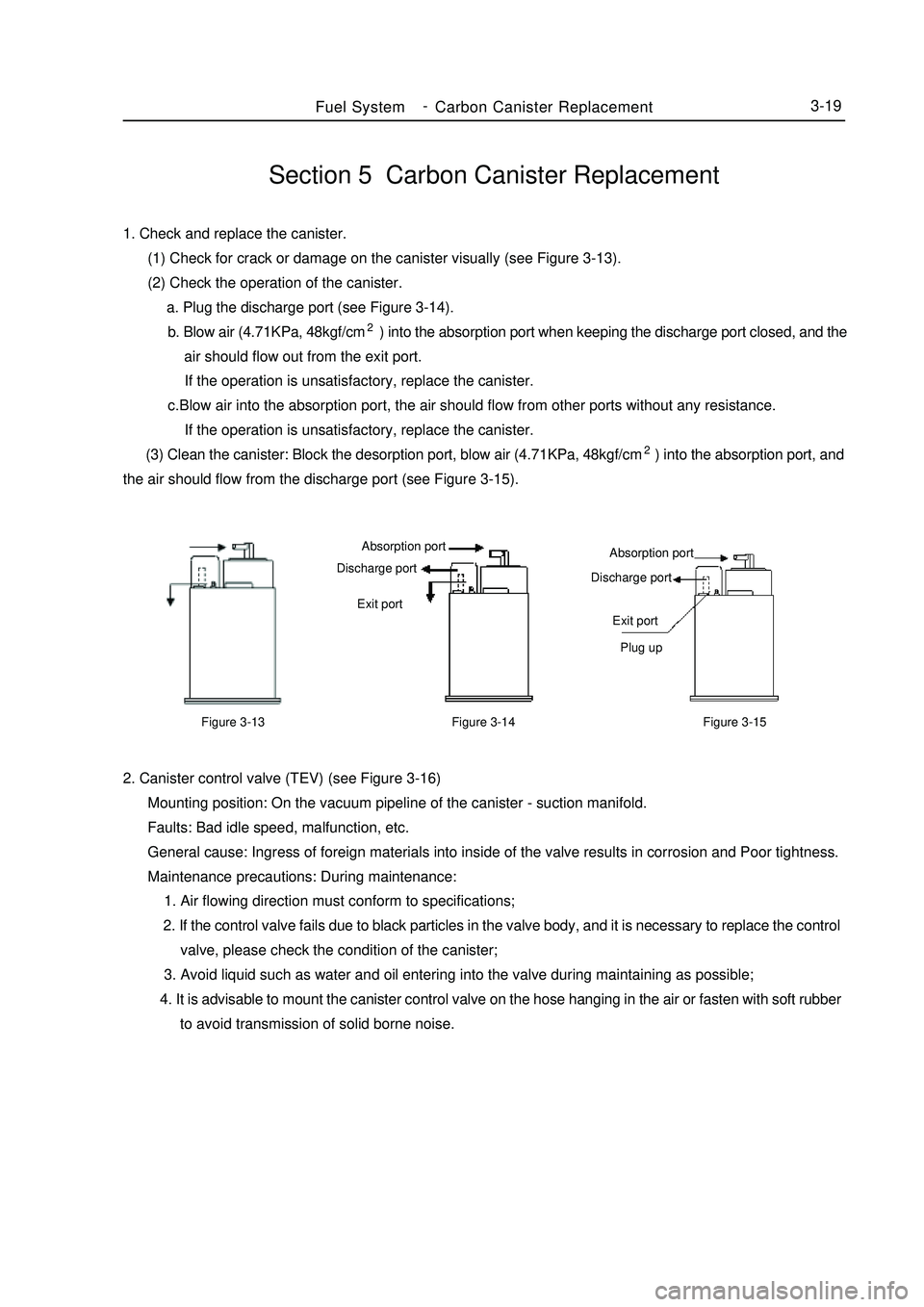
(1) Check for crack or damage on the canister visually (see Figure 3-13).
(2) Check the operation of the canister.
a. Plug the discharge port (see Figure 3-14).
b. Blow air (4.71KPa, 48kgf/cm2) into the absorption port when keeping the discharge port closed, and the
air should flow out from the exit port.
If the operation is unsatisfactory, replace the canister.
c.Blow air into the absorption port, the air should flow from other ports without any resistance.
If the operation is unsatisfactory, replace the canister.
(3) Clean the canister: Block the desorption port, blow air (4.71KPa, 48kgf/cm2) into the absorption port, and
the air should flow from the discharge port (see Figure 3-15).Fuel SystemCarbon Canister Replacement3-192. Canister control valve (TEV) (see Figure 3-16)
Mounting position: On the vacuum pipeline of the canister - suction manifold.
Faults: Bad idle speed, malfunction, etc.
General cause: Ingress of foreign materials into inside of the valve results in corrosion and Poor tightness.
Maintenance precautions: During maintenance:
1. Air flowing direction must conform to specifications;
2. If the control valve fails due to black particles in the valve body, and it is necessary to replace the control
valve, please check the condition of the canister;
3. Avoid liquid such as water and oil entering into the valve during maintaining as possible;
4. It is advisable to mount the canister control valve on the hose hanging in the air or fasten with soft rubber
to avoid transmission of solid borne noise.Figure 3-13Figure 3-15 Absorption port
Discharge port
Exit port
Plug upFigure 3-14Absorption port
Discharge port
Exit port -